Design of Catalytic Recombiners for Effective and Safe Hydrogen Removal from
Containments of Pressurized Water Reactors
P. Broeckerhoff and E.-A. Reinecke
Institut fuer Sicherheitsforschung und Reaktortechnik (ISR), Forschungszentrum Juelich (FZJ), Juelich, Germany
ABSTRACT
In case of a severe accident in pressurised or boiling water reactors a high amount of hydrogen up to about 20,000 mn 3 might be generated and released into the containments. The mixture consisting of hydrogen and oxygen may either burn or detonate, if ignited. In case of detonation the generated shock wave may endanger the components of the plant or the plant itself. Consequently, effective removal of hydrogen is required. The fact that hydrogen and oxygen react exothermally on catalytically acting surfaces already at low temperatures generating steam and heat is made use of in catalytic recombiners. They consist of substrates coated with catalyst (mainly Platinum or Palladium) which are arranged inside a casing. Being passively acting measures, recombiners do not need any additional energy supply.
To study the recombination processes in detail three REKO test facilities are available at ISR. The experimental program includes investigations of single substrates like flat plates or meshes and a complete recombiner section. The results yield knowledge on reaction kinetics and serve as basis for designing recombiners with respect to the heat transfer conditions and heat management. The experimental results show that the reaction is controlled by mass transfer.
INTRODUCTION
In the case of a severe accident in a pressurised water reactor (PWR) a great amount of hydrogen - up to about 20,000 mn 3 - might be generated and released into the containments. The fact that hydrogen and oxygen already react exothermally on catalytically acting surfaces at low temperatures thus generating steam and heat is made use of in catalytic recombiners. The latter consist of substrates coated with catalyst (mainly platinum or palladium) arranged inside a casing. Being passively acting measures, recombiners do not need any additional energy supply.
Existing recombiner systems still have some limitations in performance such as insufficient conversion rates at high hydrogen feed. In addition, they still run the risk of igniting the flammable mixture if the ignition temperature is reached due to strong heat generation caused by the exothermal reaction. Consequently, there is considerable potential for development.
Previous experimental results show that the overall reaction is controlled by mass transfer. Corresponding correlations have been derived, as described by Reinecke [ 1 ]. The major proportion of the reaction heat is removed by convection, and is thus coupled with diffusion-controlled heat production. As a consequence, any enhancement of the convective heat transfer as a cooling measure leads to an improvement of the mass transfer resulting in increasing heat production. An overheating of the catalyst elements at high hydrogen concentrations may only be avoided if the generation and removal of heat are decoupled. One approach being investigated is based on catalyst systems with adapted activity. These systems do not convert all the molecules diffusing to the catalytic surfaces thus enabling sufficient heat removal to keep temperatures below the ignition limit. The application of porous substrates permits a modular set-up with high conversion rates which may be adapted to the particular requirements. Substrates with corresponding coatings have been tested and have proved their ability in mixtures up to oxygen limitation.
E X P E R I M E N T A L
A scheme of the REKO-3 test facility for investigations of recombiner sections is shown in Figure 1. It allows sections to be tested at constant feed. The main parts are the gas supply systems and the test section. Modular assemblies, e. g. mixing device or recombiner section, may easily be replaced. Thus the investigation of different catalytic systems is simplified. The feed is composed of hydrogen, air and water vapour. Hydrogen and air may be preheated if necessary and inertising nitrogen may be injected for safety reasons. The gaseous components enter the test section at the bottom from two sides. Behind the mixing device the flow passes over the catalytic specimens. In the current experiments four fiat samples are mounted in parallel. The composition of the mixture is determined by means of a mass chromatograph at the inlet and outlet of the test section. The composition of the mixture is adjusted by means of mass flow controllers. All data are recorded and evaluated by a process system, which also enables selective control and regulation of the devices required to perform the experiments and corrective actions.
SMiRT 16, Washington DC, August 2001 Paper # 1935
Hydrogen
~1~
Air P I ~ I
6 m~l~h.~
6 m ~ n @
0 - - -
o-- ~ outlet section
( ~ ~ l ~ ° ° 1 ~ coated samples
, ,-- I section
~ 0 - - - -
Water
~
~ 1
@~
_--o ~ mixing deviceI . ~ ~
inlet sectionr / / / / / / / / / / / / / / / / / / / / / / . ~
Figure 1" REKO-3 test facility
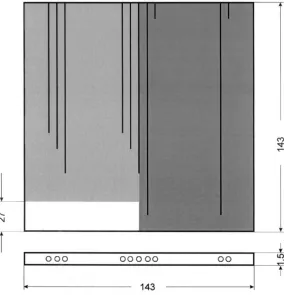
The cross section of the flow gas channel is of rectangular shape with the dimensions 146 mm x 46 mm. The square substrates consist of stainless steel with an edge length of 143 mm. They are 1.5 mm thick. Two of the four specimens are equipped with ten thermocouples each in order to determine the reaction temperatures. The positions of the thermocouples on these samples (Nos. 1 and 2 in Figure 1) are given in Figure 2. The thermocouple leads are inserted from the top via
iiiiiiiiiiiiiiiiiiiiiiiiiiiiiiiiiiiiiiiiiiii ~
iiiiiiiii!iiiiiiiiiiiiiiiiiiiiiiiiiiiiiiiili
iiiiiiiiiiiiiiiiiiiiiiiiiiiiiiiiiiiiiiiiiiii
iiiiiiiiiiiiiiiiiiiiiiiiiiiiiiiiiiiiiiiiiilil
~.~.~.~.~.~.-.~.~.~.~.~.-.~.~.~.~.~.~.~.~.~. i~,ii~,i~,~,iii~,i~,ii~,iiF,~,i~,#ii~,ii~,ii~, ~, . . ....
iiY
~:~:~:~:~:~:~:~:~:~:~:~:~:~:~:~:~:~:~:~:~:~: i)iiiiiiiiiiiiiiiiiiiiiiii;iliiiiiiiiiiiiiii ... : ... ... ... ... ... ... ... ... . . . ;i;i;ili;i;i;i;i;i;i;i;i;i;i;;;i;i;i;i;i;i;i . . .iiiiiiiiiii!iiiiiiiiiiiiiii!iiiiiiiiiiiiiiiiii . . . . . . ... ::::::::::::::::::::::::::::::::::::
. . . . v . v :
iii!iiiii!ii iiiiiiiiii
iii}iiiiiiii iiiiiiiiii
. . . . . . :.:.:.:.: . . . ... ... ... . . . ... ... . . .
iii::i::i!i::i:::, iiiii::iii::::
... :::::: : : s : : : : : :
... : : : : : : : :~:~:~:~:~ ~ ~:~:~:~:~:
iiiiiiiiiiii ...
... i!!ii!i!i!
. . . : : : : : 7 v : : L : . . . v : : : : . . .
...
iiiiiiii!ili
iiiiiiiiiiiiiiiiiiiiiiii
... ili!!ii!iiii
iiii!iiiii!ii iiiiiiiiii!ii
~iiiiiiiiiiii iiiiiiiiiiill iiiiii!i!iiil iiiiiiiiiiiii
iiiiiiiiiiii iiiiiiiiiiii
. . . . ...
3~:~:~:~:~: . . . w : v : : ... : . . . . . . . w : w : . . . . . . . . . : ...
.:.:.:-:-:.: ... v : : : : . . . .
= .. . . ~.~.~.~.~.~
~y~w iiiiiiiiii!i
1 " "
Cq
[ ...
[[[ ...
0 0 0
°'0 ...
"I
.I
143
...LO , ¢ . -
f
holes with a diameter of 0.6 mm formed by spark erosion. Thus the catalytic coating is not damaged and the flow will not be disturbed by the thermocouple leads. The investigations are carried out with samples of different coating densities. Additionally partly coated samples will be tested. On the left the figure shows an uncoated strip of a width of 27 mm, whereas on the right a completely coated sample is shown. The specimens were coated with wash coat and platinum as the catalyst similar to the catalyst sheets used in recombiners of Siemens/KWU design.
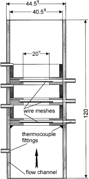
The REKO-lm test facility was built for tests of combined porous samples, see Figure 3. The diameter of the flow channel is 40.5 mm. Intemal structures enable the investigation of square porous substrates, e. g. steel meshes, with an edge length of 20 mm. The gas supply system corresponds to that of REKO-3. The gaseous mixture enters the test facility at the bottom. According to the requirements several samples may be arranged in series. Sample and gas temperatures are measured by means of thermocouples. The thermocouple fittings are positioned at the sides of the flow channel. In these experiments substrates made of heat-resistant metallic wire meshes are investigated. The samples were coated with platinum in a laboratory at FZJ without an additional wash coat.
.~ 44.5 ¢ ~,
~wire m e s h e s M ! o
i l
t'qt h e r m o c o u p l e fittings
i
flow channel
Figure 3: Recombiner section of the REKO-lm test facility
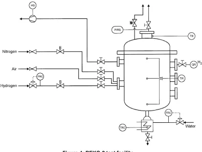
The test facility REKO-2 was originally designed and constructed for experiments on hydrogen mitigation for boiling water reactors (BWR) with inertised containments as described by Voswinckel [2]. The volume of the vessel is 0.150 m 3 at a design pressure of 10 bars. The walls of the vessel may be heated electrically to avoid condensation.
The investigations included means of hydrogen removal and containment pressure decrease to maintain the containment integrity. Experiments were performed on
1. hydrogen recombination in inertised atmosphere supported by an oxygen carrier, e. g. reaction with an oxidant,
2. separation and physical removal of hydrogen from the containment atmosphere, e. g. by means of permselective
membranes.
Passive solutions involve catalysed oxygen-donating compounds like MnO2-AgO, which has already been investigated for hydrogen removal from nuclear waste drums or containers.
Nitrogen ~-[X~] [ ~ I ,
Air ~::1~
Hydrogen ,~ [ ~
O
®
®
... j
o -,
1
o Water
Figure 4:REKO-2 test facility
The facility is currently used to investigate the catalytic reaction under natural flow conditions. First experiments address recombination on catalytically coated cylinders as a function of parameters like pressure, composition of the atmosphere and orientation of the samples under unsteady conditions. These investigations are part of the THINCAT project of the 5 th Framework Programme aiming at an alternative concept for hydrogen mitigation by means of catalytically coated thermal insulation elements.
RESULTS
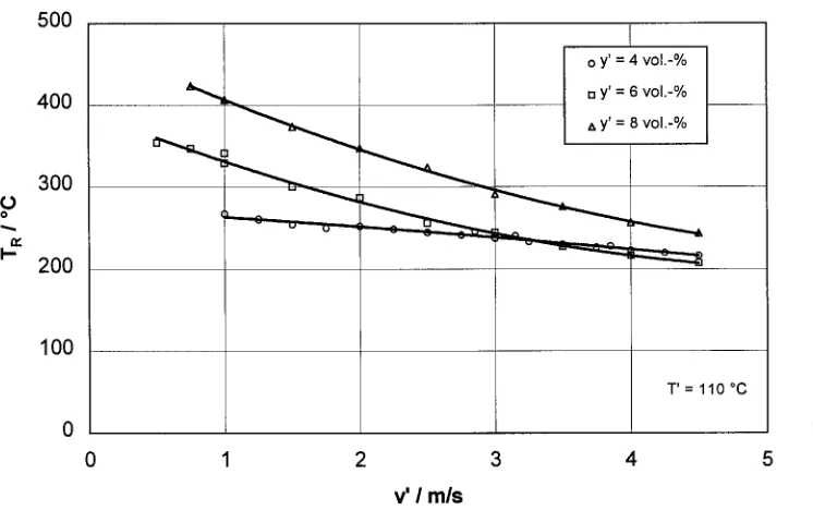
The catalytic reaction on surfaces over which the flow passes is controlled by mass transfer from the bulk flow to the active surface, as was shown in former investigations by Reinecke [1]. It was pointed out that the reaction rate is proportional to the hydrogen concentration and flow velocity. The influence of the reaction temperature, however, is weak. Porous systems like metallic wire meshes coated by means of a wash coat technique have been found to result in an effective conversion. Indeed, the high activity of the catalytic surface leads to overheating of the substrates due to insufficient heat removal by the convective flow. Consequently, the activity of the catalyst needs to be limited, which can be
t
achieved by appropriate low catalyst densities.
Figure 5 shows the reaction rates as a function of the inlet hydrogen concentration for a catalyst with adapted activity compared with a conventional wash coat catalyst for two flow velocities. It is obvious that the conversion rate is limited to a maximum value. Unlimited catalyst activity as demonstrated by the wash coat catalyst leads to further increasing conversion rates which cause substrate temperatures near the ignition limit. Thus the inlet concentration does not exceed 11 vol.-% for safety reasons. The decrease of the reaction rate at high hydrogen concentrations is probably due to the lack of oxygen. At hydrogen concentrations above 20 vol.-% the reaction stops completely.
E
L _
/
/
/
/
[] adapted activity coating; 0.5 m/s zx adapted activity coating; 1.0 m/s• washcoat catalyst; 0.5 m/s
• washcoat catalyst; 1.0 m/s
f
l Z ,--, ~, D r,! n m n0 5 10 15 20 25
y' / vol.-%
Figure 5: Comparison of limited and non-limited catalyst systems
0
0
iv, ! -
500
400
300
200
100
o Y' = 4 vol.-%
[] y' = 6 vol.-%
T ' = 110°C
0 1 2 3 4 5
v' I mls
Figure 6: Decreasing substrate temperatures with flow velocity
5
E
4
03
L _
3
- ~ ~ ~ o o n p._--
i..i
/
v ' = 1.0 m/s T ' = 50 °C
[] reaction rate zx efficiency
0 5 10 15 20 25
y' / vol.-%
80
70 60 5o 40 ~ 30 20 10
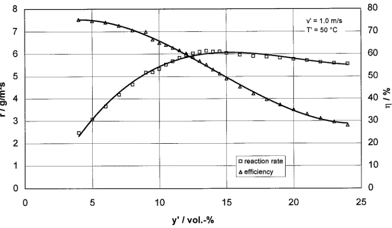
Figure 7: Performance of a modular recombiner consisting of three elements
First results of the experiments performed at the REKO-3 facility yield the distribution of substrate temperatures of a catalyst sheet inside a recombiner. Maximum temperatures are measured at the leading edge of the plate as shown in Figure 8. Temperatures decrease over the length of the specimen. The differences between the highest and the lowest temperature measured are also presented in this figure showing an almost linear dependence on the inlet hydrogen concentration. At a concentration of 4 vol.-% the maximum difference is about 175 K. Ignition temperature would already be reached at hydrogen concentrations of about 5 vol.-%. These results clearly show that unintended ignitions of plate recombiners are already likely to happen at medium hydrogen concentrations, presumably at the leading edge of the catalyst sheet. This clearly confirms the statement of the German Reactor Safety Board (RSK) in theft recommendation for backfitting nuclear power stations with autocatalytic recombiners [3] that ignition of the containment atmosphere cannot be excluded. Kanzleiter and Seidler [4] also pointed out that ignition may occur. Furthermore, the results indicate that statements about average catalyst temperatures have to be regarded with caution.
600 300
500 400
o
300
E
I- 200 100
Tmax
J
I
~ " AT
J
J
v' = 0.8 m/s T' = 25 °C
0
0 1 2 3 4 5
y' I vol.-%
250 200 150
i- 100 50
During the experiments a considerable rise of temperatures in the mixing device was observed. After dismantling the test facility a lot of particles consisting of wash coat and catalyst were found in this section. These particles had obviously been detached from the coated substrates due to thermal expansion during the recombination process. They represent a potential ignition source. As a consequence of an unintended ignition caused by loose catalyst particles Eckardt and Hill [5] proposed measures for avoiding flashback. In addition, in their German patent the authors recommend installing a sediment catcher in order to prevent the flammable mixture from being ignited.
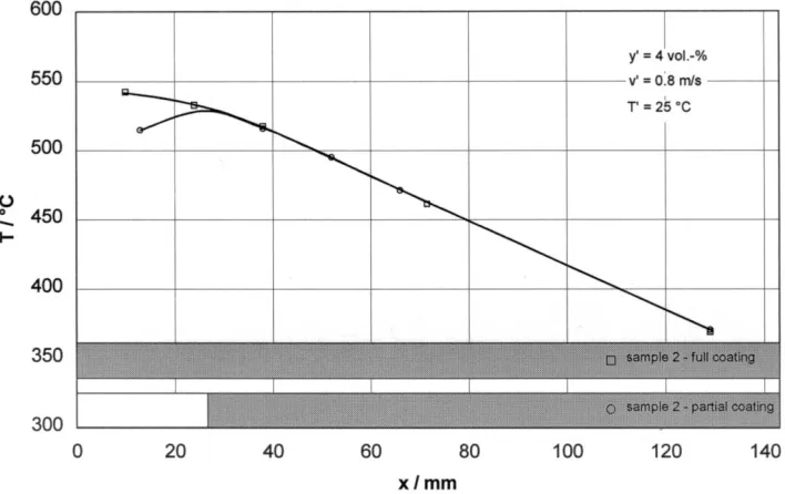
To avoid temperature peaks at the leading edge of the catalyst sheet, the first part of the specimen might be left uncoated. The effect of this measure is demonstrated in Figure 9. The substrate temperature of the uncoated region of approximately 530 °C is caused by heat conduction from the reaction zone.
0
o
I -
600
550
500
450
400
350
300
y' = 4 vol.-%
v' = 018 m/s
T' = 2~5 °C
Nl~NiNi~iNiiiNN~
~t.~:..,.~:~..-&~:::.~r., ~:~. ,.,,.,,~:~..,..~..,.::~:::~:~::.,'.t.::~..-.,,.~::
N!!NI!N~I~!ilI!NNN~
" " . . . :.':&.':-::.':~:.'-::.'..'-~.'..'.~::',,::.'. t-:;~ ~ ~:'.. ~ ~.~ &,'~, ...
I I I ~ I ... I I
N~NNNIN!N!!!N!NiNNNiNiNiiII~I!III!N!NN~NiiiiiiIIII~N%!!NiiiiiiiiiNNI~IIN~!NN~N:~ ili~!~ii~~!i
0 20 40 60 80 100 120 140
xlmm
Figure 9" Effect of partial coating on the temperature distribution
CONCLUSIONS
Experimental investigations on catalytic hydrogen recombination were conducted at FZJ using three test facilities. The results yield insight into the development potential of conventional recombiner systems as well as of innovative systems.
Detailed investigations on a recombiner section show strong temperature gradients over the surface of a catalytically coated sample. As a function of the flow velocity ignition temperature may already be reached at the leading edge at an inlet hydrogen concentration of about 5 vol.-%. The thermal strain of the substrate leads to considerable detachment of catalyst particles probably causing unintended ignition of the flammable mixture. Temperature peaks can be effectively prevented by leaving the first part of the plate uncoated.
In order to avoid overheating the catalyst elements of a recombiner even at high hydrogen concentrations a modular system of porous substrates is proposed. The metallic substrates are coated with platinum at low catalyst densities thus limiting the activity of the single specimen. A modular arrangement of these elements provides high recombination rates over a large hydrogen concentration range without igniting the mixture.
REFERENCES
1. Reinecke, E.-A., Reaktionskinetische Untersuchungen zur Auslegung yon katalytischen Wasserstoffrekombinatoren,
Ph.D. Thesis, Berichte des Forschungszentrums Juelich, Juel-3703, 1999
2. Voswinckel, M., Entwicklung und Untersuchung innovativer Sicherheitselemente zur Beseitigung yon Wasserstoff aus
inertisierten Containments von Siedewasserreaktoren, Ph.D. Thesis (in preparation)
3. Anon., ,,Bekanntmachung von Empfehlungen der Reaktor-Sicherheitskommission und der Strahlenschutzkommission",
4. Kanzleiter, T., Seidler, M., ,,Katalytische Rekombinatoren zum Abbau von Wasserstoff",