© School of Engineering, Taylor’s University
DEVELOPMENT OF THIN FILM NANOCOMPOSITE
EMBEDDED WITH GRAPHENE OXIDE FOR MgSO
4REMOVAL
I. WAN AZELEE, P. S. GOH*, W. J. LAU, B. C. NG, A. F. ISMAIL
Advanced Membrane Technology Research Centre (AMTEC), Universiti Teknologi Malaysia, 81310 Skudai, Johor, Malaysia
*Corresponding Author: peisean@petroleum.utm.my
Abstract
Thin film nanocomposite (TFN) membrane with graphene oxide (GO) embedded into the polyamide (PA) selective top layer has been developed for salt removal. 0.1 wt% of GO were dispersed in the trimesoyl chloride (TMC) organic solution and incorporated into the PA layer during interfacial polymerization with piperazine. The fabricated TFN membrane was characterized in terms of the membrane morphological structure and surface hydrophilicity. The divalent magnesium sulfate (MgSO4) salt removal
performance of the TFN was evaluated and compared with the thin film composite (TFC) counterpart. The surface morphology of the TFN membranes was altered and the surface hydrophilicity was increased with the presence of GO. The incorporation of GO has improved the permeate water flux, in which maximum improvement of 140% compared to that of TFC has been obtained, without sacrificing much on the salt rejection properties. Although further investigation is required, this study has experimentally verified the potential application of GO to heighten the salt separation performance of TFN membranes.
Keywords: GO, Thin film nanocomposite, Desalination, MgSO4 salt, Piperazine.
1.
Introduction
material has evolved based on the incorporation of nanoparticles within the membrane thin salt rejection layer or the underneath polymer substrate layer to facilitate tremendous enhancement in water permeability while maintaining promising solute rejection and providing antifouling properties [2, 3]. Recently, considerable number of studies have demonstrated that TFN membranes developed by incorporating carbon nanotubes [4], titanium dioxide [5], silica [6] and zeolite nanoparticles [7] into the thin film structures could significantly improve the nanocomposite membrane properties to impressively surpass that of commercially available nanofiltration or reverse osmosis (RO) membranes.
Graphene-based nanomaterials has been the hotspot in multidisciplinary areas owing to their outstanding physico-chemical properties. Particularly, graphene oxide (GO), which is endowed with high hydrophilicity due to the presence of abundant oxygen containing functional groups such as hydroxyl and carboxyl groups, has been extensively used as nanofiller for the fabrication of polymer nanocomposite membrane [8]. The attractive properties of ultrathin GO sheet to render new opportunities for advanced water treatment technologies based on their outstanding mechanical strength, high flux and selectivity as well as fouling resistance have been evidenced in several recent works [9-11]. Particularly, the superior capability of GO sheets to allow ultra-fast water flow in their nano-channel planars while hindering the passage of other unwanted species through carefully controlled pore sizes and functional groups available at the nanopores have opened new doors for the development and design of new class of desalination membrane [12, 13]. Additionally, the facile synthesis of GO for mass-production also offers possibilities for the fabrication of next generation cost effective and sustainable TFN desalination membranes [14, 15].
Recently, several experimental studies have been conducted to investigate the feasibility of GO in seawater desalination [16, 17]. Enhanced hydrophilicity, flux and salt rejection of GO incorporated polysulfone mixed matrix membrane has been reported by Ganesh at al. [17]. With the increasing pH of the feed solution, the highest sodium sulfate (Na2SO4) rejection of 72% has been achieved, primarily due to the presence of negative charge which were imparted by ionisable functional groups present on GO surface. Hu and Mi [16] fabricated GO membrane via layer-by-layer deposition of GO nanosheets on a polydopamine-coated polysulfone support. Prior to the deposition, the GO sheets were crosslinked with 1,3,5-benzenetricarbonyl trichloride to stabilize as well as to fine tune the charges, functionality, and spacing of the GO nanosheets. Despite their relatively low rejection (6-46%) of sodium chloride (NaCl) and Na2SO4 salts, the GO incorporated membranes possessed permeate flux ranged between 80 and 276 L/m2
.h.MPa, which is of few orders higher than that of commercial nanofiltration membranes.
(MgSO4) divalent salt rejection performance was benchmarked with its thin-film composite (TFC) counterpart.
2.
Experimental
The following subsections will provide the details of the materials used in GO synthesis as well as TFC/TFN flat sheet membrane fabrication. Different methods used in characterizing membrane properties will also be described in detail.
2.1. Materials
Graphite powder from Sigma-Aldrich was used as the starting material for GO synthesis. All the chemicals used for the synthesis of GO, i.e. sulfuric acid (H2SO4) with 98% purity, sodium nitrate (NaNO3), potassium permanganate (KMnO4), hydrogen peroxide solution (30% H2O2) and hydrochloric acid (HCl) were purchased from Merck. Polyethersulfone (PES) purchased from Solvay Specialty Polymers, USA and Polyvinylpyrrolidone (PVP) from Acros Organic, was used to fabricate substrate for TFC and TFN membrane. Trimethylchloride (TMC) and piperazine (PIP) were purchased from Sigma-Aldrich and Merck, respectively and were used to establish the PA layer. 1-methyl-2pyrrolidone (NMP) with purity 99.5% and n-hexane supplied by Merck were used without further purification. MgSO4 supplied by GCE Laboratory Chemicals were used to prepare aqueous salt solution for membrane flux and rejection determination.
2.2.
Synthesis of GO
GO was synthesized from natural graphite via modified Hummer’s method. In brief, mixture containing 1 g of graphite and 23 mL of H2SO4 was placed inside a round bottom flask (250 mL). The solution was cooled down to 0 °C by applying salt on ice cube around the round bottom flask for 20 min. Subsequently 0.5 g of NaNO3 was added while maintaining the temperature at 0 °C for other 30 min. Next, KMnO4 was added into the mixture for every 15 min, while maintaining the temperature below 20 °C throughout the addition. After the completion of KMnO4, the temperature reaction mixture was slowly raised to 30-40 °C and was kept at that temperature for 30 min and followed by the addition of water. Then to this suspension, 10 mL of hydrogen peroxide was added drop wised while the color change was observed from brown to yellowish brown. At this stage, the mixture was allowed to stir for 1 h. The mixture was filtered, washed with 100 mL of 0.1 M HCl via sonication for 1 h and lastly dried at 60 °C.
2.3. Fabrication of PA-PES TFC and GO/PA-PES TFN membranes
glass plate with a glass rod was allowed at room temperature for 30 s before undergoing phase inversion process by immerging the casting plate into a bath made up of distilled water at room temperature. The glass plate was allowed to stay in the bath until the flat sheet membrane is formed and got separated from the glass plate. The flat sheet membrane was taken out from the bath and was washed thoroughly with water to remove any residual solvent in the membrane.
The PES membrane was mounted via adhesive tape on the glass plate. Silicone rubber and a frame were attached on it to create space for stagnant solution. The PA active layer was formed by interfacial polymerization on top of the PES substrate. An average 20 mL of aqueous solution containing 2% w/v PIP (20 g PIP in 1000 mL distilled water) was poured on the membrane until all the membrane surface was covered. Later the PIP solution was removed out and was replaced with organic (hexane) solution containing 0.15 w/v % TMC (1.5 g TMC in 1000 mL n-hexane). The dipping time in both solutions was set at 45 s each. The interfacial polymerization reaction of PIP and TMC on PES membrane results in the formation of PA TFC membranes. The TFC membrane was then cured at 60 °C in the oven for 10 min. The membrane was thoroughly washed with warm water to remove unreacted amines. The GO/PES TFN membranes were fabricated as TFC membrane. 0.1 w/v% of GO were dispersed in the TMC solution and incorporated into the PA layer during the interfacial polymerization reaction.
2.3.
Characterization of GO, PA-PES TFC and GO/PA-PES
TFN membranes
Attenuated total reflectance (ATR)-infrared spectroscopy (IR) characterization was performed using a Perkin Elmer spectrometer in the wavenumber range of 4000-400 cm -1. ATR-IR characterization was used to evaluate the chemical changes of the TFN and TFC membranes. Powder X-ray diffraction (XRD) analysis of GO samples in the 2θ range of 2-40° was carried out using a Bruker D8 Advance D8-02/01-378 equipped with a Cu target (40 kV, λ=1.54Å). Thermogravimetric characterization (TGA) was carried out using a thermos-gravimetric analyzer (Mettler Toledo TGA/SDTA 85) operated at a heating rate of 20 °C/min at nitrogen atmosphere kept at the flow rate of 50 mL/min. Scanning electron microscope (SEM) (HITACHI TM3000 Tabletop microscope) was used to investigate surface morphology GO as well as the surface and cross-sectional morphology of the resultant TFC and TFNs. All samples were coated with a gold layer and examined under an accelerating voltage of 10 kV. For the cross section scanning, the membranes were fractured in liquid nitrogen. Contact angle measurements were performed under ambient conditions using contact angle meter (Dataphysics OCA 15Pro) to study the hydrophilicity of surfaces of TFC and TFN membranes.
2.4.
Performance study of PA-PES TFC and GO/PA-PES
TFN membranes
effective area of 14.6 cm2 and 1000 ppm of MgSO4 solutions as the divalent salt model. Membrane water flux, F was evaluated using the following equation:
𝐹 = 𝑡 × 𝐴𝑉 (1)
where 𝑉 is the permeate volume (L), A is the membrane area (m2) and t is the experimental time (h) to obtain V. The solute rejection was calculated using the following equation:
𝑅 = (1 −𝐶𝑝
𝐶𝑓)×100 (2)
where Cp and Cf are concentration (ppm) of permeate and feed solution, respectively.
3.
Results and Discussion
The findings obtained from the work will be discussed according to the properties of self-synthesized GO and the effect of GO on the properties of TFN membrane in the removal process of MgSO4.
3.1. Characterization of GO
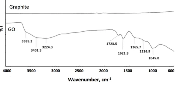
Figure 1 depicts the ATR-IR spectra of graphite and GO. While no significant peak is found in graphite, the presence of different types of oxygen functionalities in GO after the graphite sheet oxidation was confirmed with the IR spectrum. The broad absorption band stretched from 3000 -3700 cm-1 can be assigned to the stretching vibrations of O-H surface functional groups or the water molecules that adsorbed on the GO layers. This absorption band consists of several O-H stretching modes, which suggests that the O-H functional groups can exist in the forms of tertiary alcohol, phenolic and carboxylic on the GO surface [15]. The two sharp peaks appearing at 1723.5 cm-1 and 1621.8 cm-1 are attributed to the stretching vibrations from C=O and cyclic ether (epoxide) linkage as well as for
bending vibration of water molecule, respectively. Meanwhile the peak at 1216.9 cm-1 is associated to C-OH stretching vibrations and the peak at 1045 cm-1
is due to the C-O stretching vibration [18]. The oxidation of graphite sheets to GO was further verified by their XRD patterns as shown in Fig. 2.
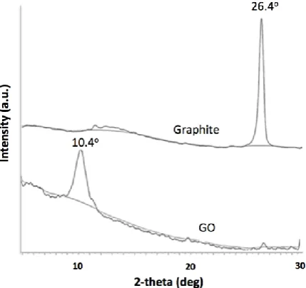
A prominent peak around 2θ =26.4° in Fig. 2 is corresponded to graphite. Upon the oxidation, GO exhibits a sharp diffraction peak around 2θ =10.4°, which is the characteristic peak of GO. The interlayer distance of GO is calculated as 8.42 Å, which is about 2.5 times larger than that of graphite (3.34 Å). The increase in this basal plane spacing is due to the functionalization of graphite with oxygen-containing groups, which implies the successful oxidative conversion of graphite into GO [19].
Fig. 2. XRD patterns of graphite and GO.
The TGA graph in Fig. 3 presents the weight loss of graphite and GO as the function of temperature. As expected, graphite exhibits high thermal stability up to 800 °C meanwhile few stages of weight loss can be clearly observed from the TGA curve of GO. The weight loss from room temperature to 150 °C is due to the evaporation of water molecules that present in the GO matrix. On the other hand, the significant weight loss around 200 °C can be caused by pyrolysis of the oxygen-containing functional groups, generating CO, CO2 and stream [20]. It is also observed that the mass of GO gradually decreases up to decomposition temperature of 800 °C.
Fig. 3. TGA curve of graphite and GO under N2 atmosphere at a heating rate of 10°C/min.
(a) (b)
(c)
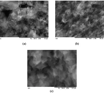
Fig. 4. SEM images of (a) graphite and (b) GO at magnification of 10,000× (c) GO at magnification of 25,000×.
100 200 300 400 500 600 700 800 35
40 45 50 55 60 65 70 75 80 85 90 95 100
Graphite
GO
W
e
ig
h
t %
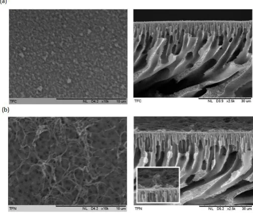
Figure 5 shows the surface and cross sectional SEM images of PA-PES TFC and GO/PA-PES TFN. The surface morphology of both samples is in good agreement with the typical characteristic of PA thin film top layer that consists of ridge-and-valley morphology. These ridge-and-valley structures are attributed to the top PA layers [23].
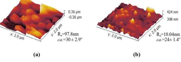
The cross sectional images of PA-PES TFC and GO/PA-PES TFN reveal that the incorporation of GO in the PA rejection layer during the interfacial polymerization process has altered the surface properties of the PA layer. Upon the incorporation of GO, more network-like structures appeared at the PA layer, which in turn suggested that the membrane microstructure can be affected by the incorporation of GO. During the interfacial polymerization, the presence of GO might have disrupted the interaction between PIP and TMC, consequently the chemical structure of the PA layer. According to Fig. 6, the surface roughness of the membrane decrease from Ra=97.8nm to Ra=10.04nm after the addition of nanoparticles. This is in agreement with Rajaeian et al. [24] which observed a smooth morphology upon the addition of nanoparticles and indicates their distribution on the membrane surface so that the peak-to-valley structures of the membrane surface are filled with nanoparticles.
Fig. 5. SEM surface (magnification of 10K) and cross sectional images
(magnification of 2,500) of (a) PA-PES TFC and (b) GO/PA-PES TFN (Inset shows the cross sectional image at 10,000 magnification).
The contact angle measurement revealed that the contact angle of PA-PES TFC is ca. 30± 2.9o whereas with the incorporation of GO at the PA rejection layer, the contact angle of the GO/PA-PES TFN has reasonably reduced to ca.
phenomenon can be attributed to the following aspects. Firstly, the abundant hydrophilic hydroxyl groups that attached on the GO surface can favourably form strong hydrogen bond interaction with the water molecule to improve the hydrophilicity of the GO/PA-PES TFN membrane [25]. Secondly, the incorporation of GO may disrupt the interfacial polymerization to certain extend where partial of the acyl chloride groups in TMC remained on the surface without reacting with amine groups, the hydrolysis of acyl chloride may also take place and generate more carboxyl acid functional groups that further increase the surface hydrophilicity [26].
(a) (b)
Fig. 6. 3D AFM images for (a) PA-PES TFC and (b) GO/PA-PES TFN membranes.
3.2. Performance evaluation of PA-PES TFC and GO/PA-PES TFN
membranes
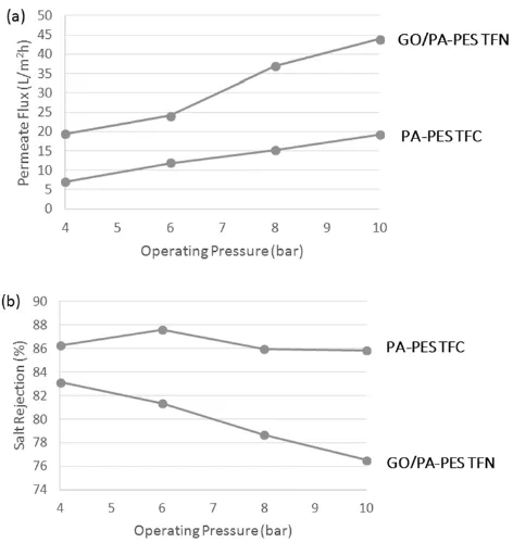
The separation performance of the PA-PES TFC and GO/PA-PES TFN membranes was examined by using MgSO4 as a representative divalent salt model. MgSO4 is a common divalent salt that is widely used and occurs to have high rejection on NF membranes [27, 28]. The separation performance of the membranes in term of permeate water flux and MgSO4 rejection under applied pressure of 4-10 bar is compared and the results are shown in Fig. 7.
The maximum permeate water flux of PA-PES TFC and GO/PA-PES TFN membranes under the studied conditions was recorded as 1.7 and 4.8 Lm-2h -1bar-1, respectively. Under all applied pressures, the water permeate flux of GO/PA-PES TFN has been notably increased compared to that of PA-PES TFC, where maximum of 140% enhancement has been observed at 8 bar of applied pressure. The significant improved water permeability can be ascribed to the two-dimensional channels formed between the stacked between GO layers that provided primary passages for water transport. Furthermore, due to the distortions from high proportion of sp3 C-O bonds, the formation of amorphous regions with nanoscale wrinkles and structural defects in the basal plane o f GO sheets could also further facilitate the transport of water molecule, henc e improve the water flux [29].
As shown in Fig. 7(b), the MgSO4 salt rejection of both thin film membranes gradually dropped with the increasing applied pressure. Upon comparison, it was found that the salt rejection of GO/PA-PES TFN membranes ranged between 76 and 83% was slightly lower than that of PA-PES TFC membranes that ranged between 86 and 88%. Although it has been pointed out that negative charges can
Ra=97.8nm
ca.=30± 2.9o Ra=10.04nm
be imparted by the ionisable functional groups that present on GO surface to promote higher salt rejection particularly at elevated pH [17], such improvement was not observed in the current study mainly attributed to the threshold GO loading of 0.1% used. However, it is believed that by adjusting the GO loading and the thin film synthesis protocol, both water flux and salt rejection performance can be further improved. When compared with other published studies as listed in Table 1, the incorporation of GO in TFN membrane in the current study shows relatively good performance in terms of water permeability with stable MgSO4 rejection.
Fig. 7. (a) Water permeate flux and (b) MgSO4 rejection of PA-PES TFC and GO/PA-PES TFN in 1000 ppm MgSO4 solution
as a function of operating pressure.
Table 1. Comparison of current composite membrane with commercially available membrane (Dow-Filmtec NF90 and Nitto-Denko NTR-7450) and other self-fabricated NF membrane (PES-5% Fe3O4 and PES-10% Fe3O4).
Membrane PWP
(L/m2
h bar)
MgSO4
rej. (%)
Operating pressure
(bar)
MgSO4
conc. (ppm) Ref.
PA-PES TFC 1.7 86.3 4 1000 Current
GO/PA-PES TFN 4.8 83.2 4 1000
Dow-Filmtec NF90 6.7 97 4.8 2000 [30]
Nitto-Denko NTR-7450 10.9 48 10 1000
PES-5% Fe3O4 4.9 45 10 2000 [31]
4. Conclusions
TFN membranes with GO embedded into the PA selective top layer has been developed for salt removal. The presence of GO at the selective layer has altered the morphological structure of the PA layer and increased the surface hydrophilicity of the TFN. The permeate water flux of GO/PA-PES TFN has been improved compared to that of PA-PES TFC, where maximum of 140% enhancement has been observed. The results indicated that the permeate water flux of the fabricated TFN can be significant increased with the presence of GO. Despite the slight decline of the MgSO4 salt rejection, compared to the other well established carbon-based nanomaterials such as carbon nanotubes, the inexpensive GO materials offer new opportunities to modify the physic-chemical properties, hence enhance the salt separation performance of TFN polyamide membranes, particularly in term of permeate water flux. The findings of this study can provide valuable guidance for the design and manufacture of graphene-base RO membranes for effective salt removal. It is also expected that, the surface functionalization of GO through reactions such as amination and silylation can serve as a feasible strategy to properly engineer the nanostructure of stacked GO nanosheets as well as alter the surface charges of the membrane so that desirable salt removal performance can be achieved. Additional work is needed to verify such possibilities and the scopes are currently under investigation.
Acknowledgements
The authors would like to acknowledge the financial supports provided by Ministry of Education (FRGS Grant: 4F306) and Universiti Teknologi Malaysia (Research University Grant: 02G43).
References
1. Subramani, A.; Voutchkov, N.; and Jacangelo, J.G. (2014). Desalination energy minimization using thin film nanocomposite membranes. Desalination, 350, 35-43. 2. Kim, W.G.; and Nair, S. (2013). Membranes from nanoporous 1D and 2D materials:
A review of opportunities, developments, and challenges. Chemical Engineering Science, 104, 908-924.
3. Perreault, F.; Tousley, M.E.; and Elimelech, M. (2014). Thin-film composite polyamide membranes functionalized with biocidal graphene oxide nanosheets.
Environmental Science & Technology Letters, 1, 71-76.
4. Amini, M.; Jahanshahi, M.; and Rahimpour, A. (2013). Synthesis of novel thin film nanocomposite (TFN) forward osmosis membranes using functionalized multi-walled carbon nanotubes. Journal of Membrane Science, 435, 233-241.
5. Emadzadeh, D.; Lau, W.J.; Matsuura, T.; Rahbari-Sisakht M.; and Ismail A.F. (2014). A novel thin film composite forward osmosis membrane prepared from PSf-TiO2 nanocomposite substrate for water desalination. Chemical Engineering
Journal, 237, 70-80.
nanocomposite reverse osmosis membrane for seawater desalination. Desalination, 325, 76-83.
7. Dong, H.; Zhao, L.; Zhang, L.; Chen, H.; Gao, C.; and Ho, W.W. (2015). High-flux reverse osmosis membranes incorporated with NaY zeolite nanoparticles for brackish water desalination. Journal of Membrane Science, 476, 373-383.
8. Gonçalves, G.; Marques, P.A.A.P.; Barros-Timmons, A.; Bdkin, I.; Singh, M.K.; Emami, N.; and Gracio, J. (2010). Graphene oxide modified with PMMA via ATRP as a reinforcement filler. Journal of Materials Chemistry, 20, 9927-9934.
9. Zhao, C.; Xu, X.; Chen, J.; and Yang, F. (2013). Effect of graphene oxide concentration on the morphologies and antifouling properties of PVDF ultrafiltration membranes. Journal of Environmental Chemical Engineering, 1, 349-354.
10. Wang, Z.; Yu, H.; Xia, J.; Zhang, F.; Li, F.; Xia, Y.; and Li, Y. (2012). Novel GO-blended PVDF ultrafiltration membranes. Desalination, 299, 50-54.
11. Xu, Z.; Zhang, J.; Shan, M.; Li, Y.; Li, B.; Niu, J.; Zhou, B.; and Qian, X. (2014). Organosilane-functionalized graphene oxide for enhanced antifouling and mechanical properties of polyvinylidene fluoride ultrafiltration membranes. Journal of Membrane Science, 458, 1-13.
12. Cohen-Tanugi, D.; and Grossman, J.C. (2012). Water desalination across nanoporous graphene. Nano letters, 12, 3602-3608.
13. Huang, H.; Ying, Y.; and Peng, X. (2014). Graphene oxide nanosheet: an emerging star material for novel separation membranes. Journal of Materials Chemistry A, 2, 13772-13782.
14. Goh, P.S.; and Ismail, A.F. (2015). Graphene-based nanomaterial: The state-of-the-art material for cutting edge desalination technology. Desalination, 356, 115-128. 15. Mahmoud, K.A.; Mansoor, B.; Mansour, A.; and Khraisheh, M. (2015). Functional
graphene nanosheets: The next generation membranes for water desalination.
Desalination, 356, 208-225.
16. Hu, M.; and Mi, B. (2013). Enabling graphene oxide nanosheets as water separation membranes. Environmental Science & Technology, 47, 3715-3723.
17. Ganesh, B.M.; Isloor, A.M.; and Ismail, A.F. (2013). Enhanced hydrophilicity and salt rejection study of graphene oxide-polysulfone mixed matrix membrane.
Desalination, 313, 199-207.
18. Xu, Y.; Bai, H.; Lu, G.; Li, C.; and Shi, G. (2008). Flexible graphene films via the filtration of water-soluble noncovalent functionalized graphene sheets. Journal of the American Chemical Society, 130, 5856-5857.
19. Kou, L.; He, H.; and Gao, C. (2010). Click chemistry approach to functionalize two dimensional macromolecules of graphene oxide nanosheets. Nano-Micro Letters, 2, 177-183.
20. Jeong, H.K.; Lee, Y.P.; Jin, M.H.; Kim, E.S.; Bae, J.J.; and Lee, Y.H. (2009). Thermal stability of graphite oxide. Chemical Physics Letters, 470, 255-258. 21. Shahriary, L.; and Athawale, A.A. (2014). Graphene Oxide Synthesized by using
Modified Hummers Approach. International Journal of Renewable Energy and Environmental Engineering, 2, 58-63.
obtained by coating polyamide over polysulfone membranes of different pore dimensions. Journal of Membrane Science, 278, 19-25.
23. Hofs, B.; Schurer, R.; Harmsen, D.J.H.; Ceccarelli, C.; Beerendonk, E.F.; and Cornelissen, E.R. (2013). Characterization and performance of a commercial thin film nanocomposite seawater reverse osmosis membrane and comparison with a thin film composite. Journal of Membrane Science, 446, 68-78.
24. Rajaeian, B.; Rahimpour, A.; Tade, M.; and Liu, S. (2013). Fabrication and characterization of polyamide thin film nanocomposite (TFN) nanofiltration membrane impregnated with TiO2 nanoparticles. Desalination, 313, 176-188. 25. Li, Q.; Pan, X.; Hou, C.; Jin, Y.; Dai, H.; Wang, H.; Zhao, X.; Liu, X. (2012).
Exploring the dependence of bulk properties on surface chemistries and microstructures of commercially composite RO membranes by novel characterization approaches. Desalination, 292, 9-18.
26 Kim, C.K.; Kim, J.H.; Roh, I.J.; Kim, J.J. (2000). The changes of membrane performance with polyamide molecular structure in the reverse osmosis process.
Journal of Membrane Science, 165, 189-199.
27. Mohammad, A. W.; Teow, Y. H.; Ang, W. L.; Chung, Y. T.; Oatley-radcliffe, D. L.; and Hilal, N. (2015). Nano filtration membranes review: Recent advances and future prospects. Desalination, 356, 226-254.
28. Wu, D.; Yu, S.; Lawless, D.; Feng, X. (2015). Thin film composite noanfiltration membranes fabricated from polymeric amine polyethylenimine imbedded with monomeric amine piperazine for enhanced salt separations.
Reactive and Functional Polymers, 86, 168-183.
29. Compton, O.C.; and Nguyen, S.B.T. (2010). Graphene oxide, highly reduced graphene oxide, and graphene: versatile building blocks for carbon-based materials.
Small, 6, 711 - 723.
30. Fang, W.; Shi, L.; and Wang, R. (2014). Mixed polyamide-based composite nanofiltration hollow fiber membranes with improved low-pressure water softening capability. Journal of Membrane Science, 468, 52-61.