Development of New Correlations for Improved Integrity Assessment of Nuclear
Reactor Piping Components
J.Chattopadhyay*, B.K.Dutta, K.K.Vaze
Reactor Safety Division, Hall-7, Bhabha Atomic Research Centre, Mumbai, INDIA-400085
*Email: [email protected]
ABSTRACT
To investigate several unresolved issues and to improve upon the existing equations for integrity assessment of piping components, a comprehensive Component Integrity Test Program (CITP) was initiated at BARC, India. As a part of this program, several fracture tests have been conducted on straight pipes and pipe bends, which forms a valuable data base. Simultaneously, analytical work have been undertaken to propose the improvements in the existing equations for optimized and more accurate integrity assessment of piping components. As an outcome of this analytical investigations, generalized equation of ηpl and γ have been proposed to evaluate J-R curve, study of transferability of fracture properties from specimen to component has been done to highlight the role of constraint parameter, new limit moment equations of elbows have been proposed and new J and COD estimation schemes of throughwall cracked elbows have been proposed. All these newly proposed equations have been experimentally validated with the test data generated under CITP.
INTRODUCTION
Integrity assessment of piping components is very essential for safe and reliable operation of all types of process power plants. It is especially important for nuclear power plants because of the application of leak-before-break (LBB) concept which involves detailed integrity assessment of primary heat transport piping systems taking into account the postulated cracks. The mechanical evaluation of pipe failures has evolved over time. The main effort in evaluating the mechanical and structural behavior or pressurized components started about 1950. Since that time, numerous investigations have been performed to assess the loading capacity and failure behavior of piping components. Investigations have also focused on determining failure loads and quantifying the margins of safety. While a considerable work has already been done in the development of integrity assessment procedure of cracked/un-cracked piping components, some issues are still unresolved or not fully understood, especially regarding elbows.
Against this backdrop, a comprehensive Component Integrity Test Program was initiated at Reactor Safety Division, BARC, India. In this program, large number of full scale tests on straight pipe and elbows of various sizes with various crack configurations subjected to different loading conditions were carried out. Subsequently, these test data base was utilized scientifically to develop a number of new equations that may be used for improved integrity assessment of piping components. The present report first describes briefly the tests carried out and then its scientific use to develop new equations.
EXPERIMENTAL WORK
In the experimental investigations, fracture mechanics tests are carried out on cracked pipes and elbows under quasi-static monotonic loading. Total 45 tests consisting of 27 pipes of various sizes (200 - 400 mm diameter) with circumferential cracks of various angles (30o-150o), configurations (throughwall/surface), materials (base/weld)
and 18 elbows of various sizes (200 - 400 mm diameter) with throughwall cracks of various angles (60o-120o),
Table 1 Details of Pipe Test Specimens
Crack angle, 2θo
Test no. Outer
Dia. (mm)
Thickness (mm)
Outer Span (mm)
Inner
Span (mm) As machined After fatigue pre-crack SP BM TWC8-1*
SP BM TWC8-2 SP BM TWC8-3 SP BM TWC8-4 SP BM TWC16-1 SP BM TWC16-2 SP BM TWC16-3
219 219 219 219 406 406 406
15.15 15.10 15.29 15.11 32.38 32.15 32.36
4000 4000 4000 4000 5820 5820 5820
1480 1480 1480 1480 1480 1480 1480
60.0 90.0 120.0 150.0 90.9 121.4 153.0
65.6 93.9 126.4 157.0 96.0 126.3 157.8
*SP = Straight Pipe, BM = Base Metal, TWC = Through Wall Crack, First number represent the nominal pipe diameter in inch and second number represents the test no.
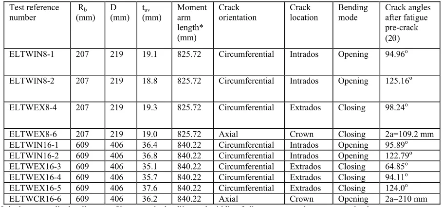
Table 2 Details of Elbow Test Specimens
Test reference number
Rb
(mm) D (mm)
tav
(mm)
Moment arm length* (mm)
Crack orientation
Crack location
Bending mode
Crack angles after fatigue pre-crack (2θ)
ELTWIN8-1 207 219 19.1 825.72 Circumferential Intrados Opening 94.96o
ELTWIN8-2 207 219 18.8 825.72 Circumferential Intrados Opening 125.16o
ELTWEX8-4 207 219 19.3 825.72 Circumferential Extrados Closing 98.24o
ELTWEX8-6 207 219 19.0 825.72 Axial Crown Closing 2a=109.2 mm
ELTWIN16-1 609 406 36.4 840.22 Circumferential Intrados Opening 95.89o
ELTWIN16-2 609 406 36.8 840.22 Circumferential Intrados Opening 122.79o
ELTWEX16-3 609 406 35.1 840.22 Circumferential Extrados Closing 64.85o
ELTWEX16-4 609 406 35.7 840.22 Circumferential Extrados Closing 94.11o
ELTWEX16-5 609 406 37.6 840.22 Circumferential Extrados Closing 124.0o
ELTWCR16-6 609 406 36.2 840.22 Axial Crown Opening 2a=210 mm
* It is the perpendicular distance of between the loadline and middle of elbow cross section to convert load to moment
Table 3 Mechanical Properties of SA 333 Gr 6 steel at Room Temperature
200 mm NB pipe
material 400 mm NB pipe material
Yield stress, σy 288 MPa 312 MPa
Ultimate tensile stress, σu 420 MPa 459 MPa
Young’s modulus of elasticity, E 203 GPa 203 GPa
Percentage elongation 36.2 39.1
Percentage reduction in area 76.64 76.15
Poisson’s ratio, ν 0.3 0.3
Ramberg-Osgood coefficient (α)with reference stress equal to yield stress
10.759 10.249
Ramberg-Osgood hardening exponent (n) Initiation toughness, (Ji)SZW
4.301
220 N/mm 4.23 236 N/mm
ANALYTICAL WORK
Various analytical work have been undertaken in RSD, BARC to propose the improvements in the existing equations for optimized and more accurate integrity assessment of piping components, specially for Break-Preclusion or Leak-Before-Break analysis of nuclear power plant piping. The test data developed above have been extensively used for experimental validation of the proposed improvements. The major analytical works are as follows:
• Study of transferability of fracture properties from specimen to component
• New limit moment equations of elbows
• New J and COD estimation schemes of throughwall cracked elbows These analytical works are described in brief in the subsequent sections.
GENERALIZED EQUATION OF ηPL AND γ TO EVALUATE J-R CURVE
The evaluation of J-integral from test data generally requires the experimental load vs. load-line-displacement and load vs. crack growth data. Rice et al [3] proposed splitting the total J-integral into elastic (Je) and plastic (Jp) components:
J = Je + Jp (1)
Je is evaluated as:
Je = K2 / E’ (2)
where, E’ = E for plane stress case and E’ = E / (1-ν2) for plane strain case, K is the elastic stress intensity factor, E is the Young’s modulus and νis the Poisson’s ratio. The general expression to evaluate Jp from experimental data is as follows [4-5]:
pl
pl o
= . . + . .
o
a
p pl p
a
J P d J da
∆
η ∆ γ
∫
∫
(3)where, P is the total applied load, ∆plis the plastic load-line-displacement due to crack only, ao is the initial crack length per crack tip, a is the current crack length per crack tip, ‘ηpl’ and ‘γ’ are two geometry and loading dependent functions.
The earlier ‘ηpl’ and‘γ’ functions had been derived from dimensional analyses that were specific to the geometry and loading conditions. No general formula was available. Chattopadhyay et al [6] derived the limit load-based general expressions of ‘ηpl’ and‘γ’ functions as follows:
pl
1 = - L.
L F
A F
∂ η
∂ and
2 / 2
= / L
L
F a
F a
∂ ∂
γ
∂ ∂ (4)
Utilizing these general expressions, new ‘ηpl’ and‘γ’ functions for following pipe/elbow geometry under various loading conditions, for which no solutions are available in the open literature, have been derived.
•
Throughwall circumferentially cracked thick pipe under combined bending and tension•
Pipe with constant depth part-through circumferential crack under combined bending moment and axial tension•
Pipe with semi-elliptical part-throughwall circumferential crack under axial tension•
Pipe with semi-elliptical part-throughwall circumferential crack under combined bending moment and axial tension•
Pipe with full circumferential part-throughwall crack under axial tension•
Elbow with throughwall circumferential crack under in-plane bending moment
Crcak at extrados under closing moment
Crack at intrados under opening moment•
Elbow with throughwall axial crack at crown under in-plane bending moment
Closing moment
Opening momentDetails of these derivations and experimental/numerical validations of some of these new ‘ηpl’ and ‘γ’ functions are available in [7-8].
STUDY OF TRANSFERABILITY OF FRACTURE PROPERTIES FROM SPECIMEN TO COMPONENT
deformation (e.g. J-integral) and the second parameter is used to quantify the level of stress triaxiality. If the triaxial conditions are found to be similar then it is believed that the J-R curves are transferable.
The multi-axiality quotient, ‘q’ as proposed by Clausmeyer et al [9] and later modified by Pavankumar et al [10] is used as constraint parameter. The parameter is as defined below :
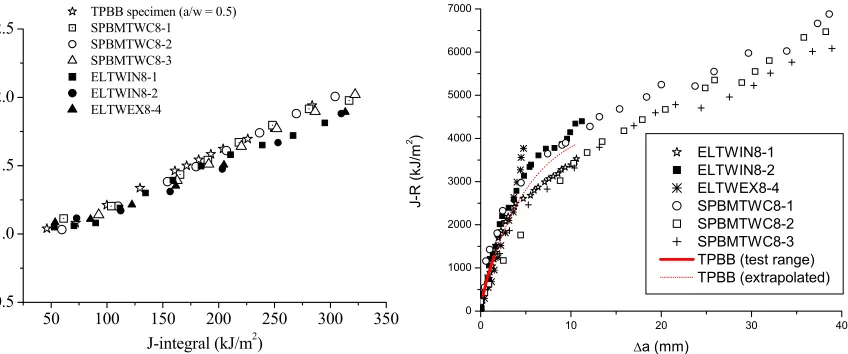
Where, q = (1/√3)(σe/σm) with σe = von-Mises effective stress, σm = hydrostatic stress, qc is the critical value of multi-axiality quotient (= 0.27), dx is the distance across the ligament, J is the J-integral, σ0is the yield stress. These parameters (i.e. q and Anq) have been evaluated for side grooved TPB specimen (a/w = 0.5) which are machined from 200 mm NB pipes, 200 mm NB pipes having various sizes of throughwall circumferential crack subjected to four point bending load (see Table 1 for details) and also for 200 mm NB elbows having throughwall circumferential cracks at extrados/intrados subjected to closing/opening bending moment (see Table 2 for details). Figure 1 shows the variation of ‘Anq’ with J-integral for TPB specimen and pipes and elbows. It may be seen that stress triaxiality ahead of crack tip, quantified by the parameter ‘Anq’ is almost identical for all these pipes and elbows and TPB specimen. This implies that J-R curves generated from all these components and specimens should be same. Figure 2 shows the J-R curve generated from TPB specimen, 3 pipes and 3 elbows mentioned in Tables 1 and 2. The J-R curves from pipes are taken from [1-2]. The J-R curves of elbows have been evaluated using the newly proposed ‘ηpl’ and ‘γ’ functions and details are available in [6-8]. Figure 2 shows that J-R curve from all these components and specimens are indeed identical, because of identical stress triaxialities in a region ahead of the crack tip. This shows the role of stress triaxialities in the transferability of J-R curve from specimen to component.
50 100 150 200 250 300 350
0.5 1.0 1.5 2.0 2.5
A n q
J-integral (kJ/m2) TPBB specimen (a/w = 0.5) SPBMTWC8-1 SPBMTWC8-2 SPBMTWC8-3 ELTWIN8-1 ELTWIN8-2 ELTWEX8-4
0 10 20 30 40
0 1000 2000 3000 4000 5000 6000 7000
ELTWIN8-1 ELTWIN8-2 ELTWEX8-4 SPBMTWC8-1 SPBMTWC8-2 SPBMTWC8-3 TPBB (test range) TPBB (extrapolated)
J-R (k
J/
m
2 )
∆a (mm)
Fig.1 Variation of constraint parameter (Anq) Fig.2 Comparison of J-R curves from TPB specimen with J-integral for various pipes and elbows and through-wall cracked pipes and elbows
DEVELOPMENT OF NEW LIMIT LOAD EQUATIONS FOR PIPE BENDS
Pipe bends or elbows are commonly used components in a piping system. It is important to know its limit moment for the safe operation of the plant. The term ‘limit load’ is used in this paper in a generic sense to indicate plastic collapse load. In this paper, plastic collapse load has always been evaluated by twice elastic slope (TES) criterion. Elbows may potentially contain cracks due to manufacturing defects or service related degradation mechanisms. It is very important to know the effect of cracks on the plastic collapse moment (PCM) of elbows for integrity assessment of the piping system. The PCM of any cracked component is generally expressed as product of PCM of defect-free component and a weakening factor due to the presence of crack. Therefore, before studying the PCM of any cracked component, one should know the PCM of a defect-free component. In comparison to the straight pipe, the deformation characteristics of pipe bend has additional complexities due to ovalisation of elbow cross section, which makes the deformation behaviour completely different for opening and closing mode of
5J/
J/ nq 5J/
c J/
qdx
A (5) q dx
0
0 0
0
σ
σ σ
σ
=
∫
bending moment. Additionally, bending moment induces both axial and circumferential stresses at a significant level in pipe bends, which makes it imperative to postulate both circumferential and axial crack configurations. Further, an elbow is often subjected to combined internal pressure and bending moment in actual service condition. Internal pressure affects the load carrying capacity of elbows (specially thin ones) quite significantly. Finally wall thickness and bend radius of elbows also determine its deformation characteristics. These large numbers of variables make the analysis of pipe bends quite elaborate and complex. As a part of the comprehensive program initiated by RSD, BARC, new closed-form equations have been proposed to evaluate plastic collapse moments of pipe bends considering almost all the variables mentioned above. The following cases have been studied.
Three crack configurations: (i) Defect free elbow, (ii) Throughwall circumferentially cracked elbow (iii) Throughwall axially cracked elbow
For each crack configurations two in-plane bending modes: (i) Closing mode, (ii) Opening mode
For each bending mode two loadings: (i) Pure in-plane bending moment, (ii) Combined loading of internal pressure and in-plane bending moment
For each of the above geometry and load configuration, several radii to thickness ratio (R/t) and crack sizes (for cracked elbows) have been considered. The following sections describe briefly the basic methodology followed to develop these limit moment equations, results and discussion. More details may be found in [11].
Methodology
The finite element method is used to conduct the parametric study to develop the equation for plastic collapse moment (PCM) of pipe bends. Geometrically, a 90o cracked elbow is characterized by three parameters, namely, Rb/R,R/t and a parameter to denote crack size, which is 2θ for circumferential crack and a/Dm for axial crack, where
a is the semi-axial crack length, θ is the semi-circumferential crack angle, Rb is the mean bend radius of elbowand
R, Dm and t are the mean radius, mean diameter and wall thickness of the elbow cross section respectively. Table 5 shows different combinations of these parameters taken in the study. In the present analyses, the elbow is connected with straight pipes of length equal to the six times the mean cross sectional radius.
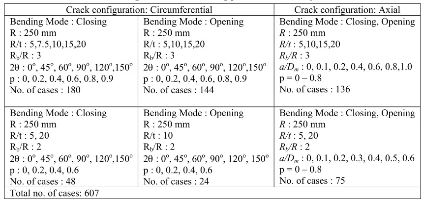
Table 4 Various geometric and loading parameters of analyzed elbows
Crack configuration: Circumferential Crack configuration: Axial
Bending Mode : Closing R : 250 mm
R/t : 5,7.5,10,15,20 Rb/R : 3
2θ : 0o, 45o, 60o, 90o, 120o,150o
p : 0, 0.2, 0.4, 0.6, 0.8, 0.9 No. of cases : 180
Bending Mode : Opening R : 250 mm
R/t : 5,10,15,20 Rb/R : 3
2θ : 0o, 45o, 60o, 90o, 120o,150o
p : 0, 0.2, 0.4, 0.6, 0.8, 0.9 No. of cases : 144
Bending Mode : Closing, Opening
R : 250 mm
R/t : 5,10,15,20
Rb/R : 3
a/Dm : 0, 0.1, 0.2, 0.4, 0.6, 0.8,1.0 p = 0 – 0.8
No. of cases : 136
Bending Mode : Closing R : 250 mm
R/t : 5, 20 Rb/R : 2
2θ : 0o, 45o, 60o, 90o, 120o,150o
p : 0, 0.2, 0.4, 0.6 No. of cases : 48
Bending Mode : Opening R : 250 mm
R/t : 10 Rb/R : 2
2θ : 0o, 45o, 60o, 90o, 120o, 150o
p : 0, 0.2, 0.4, 0.6 No. of cases : 24
Bending Mode : Closing, Opening
R : 250 mm
R/t : 5, 20
Rb/R : 2
a/Dm : 0, 0.1, 0.2, 0.3, 0.4, 0.5, 0.6 p = 0 – 0.8
No. of cases : 75 Total no. of cases: 607
Results and Discussion
For each case, PCM is evaluated from the moment rotation curve by TES method. Before analyzing cracked elbows, defect-free elbows are analyzed. Subsequently, the weakening factor because of the presence of crack has been quantified by evaluating the ratio of PCM of cracked and defect-free elbows (X = ML/Mo). Finally, closed-form equations of PCM are proposed by curve fitting the FE data. The results of defect-free elbows are first presented and then the effect of cracks on the PCM is shown.
Defect-free elbow
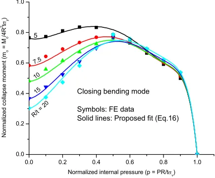
Figure 3 shows the variation of normalized PCM (mo = Mo/(4R2tσy)) with normalized internal pressure (p =
PR/(tσy)) for various elbow thicknesses (R/t).
0.0 0.2 0.4 0.6 0.8 1.0
0.0 0.2 0.4 0.6 0.8 1.0
5
7.5
10
15
R/t = 20
Closing bending mode
Symbols: FE data
Solid lines: Proposed fit (Eq.16)
N
or
m
alize
d c
oll
ap
se
mome
nt
(m
o
= M
o
/4
R
2tσ
y
)
Normalized internal pressure (p = PR/tσy)
Fig.3 Variation of normalized closing PCM (mo) with normalized internal pressures (p) of defect-free elbows
The ovalisation of the elbow cross section plays an important role in its collapse. The application of uniform internal pressure opposes the ovalisation of the elbow cross-section, thus delaying the collapse phenomenon. Ovalisation is more prominent in case of thin walled elbow. That is why internal pressure enhances the limit moments significantly in thin walled elbow. However, if the internal pressure is increased beyond a limit, the hoop stress due to internal pressure nullifies the beneficial effect on the limit moments and finally the limit moment starts reducing with further increase in internal pressure. The FE data of these normalized parameters (mo, p, h) have been best fitted and two separate equations are proposed to evaluate the PCM of defect-free elbow under combined loading of internal pressure and in-plane closing and opening bending moment respectively:
1.418
2 / 3 12.129
2 0.223
2.071
1.075 8.41 1
4 o o
y
M p
m h p p
R t h
= = + + −
σ
(6)
1/ 3 9.6431
2 1/ 3
1.2182
0.0617 1.0485 7.8509 1
4 o o
y
M p
m h p p
R t h
= = − + + + −
σ
(7)
Applicability: 2 ≤ (Rb/R)≤ 3, 5 ≤ (R/t)≤ 20, 0 ≤ p ≤ 1
Throughwall Circumferentially Cracked Elbow
Closing mode
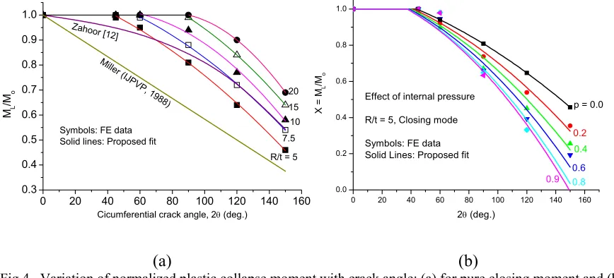
It is seen from Fig.4a that there is a threshold crack angle below which a through wall circumferential crack at elbow extrados does not weaken an elbow. This threshold crack angle increases with increasing R/t.
0 20 40 60 80 100 120 140 160
0.3 0.4 0.5 0.6 0.7 0.8 0.9 1.0
Miller (IJ PVP
, 1988) Zahoor [12]
20 15 10 7.5
R/t = 5
ML /Mo
Cicumferential crack angle, 2θ (deg.)
Symbols: FE data Solid lines: Proposed fit
0 20 40 60 80 100 120 140 160
0.0 0.2 0.4 0.6 0.8 1.0
0.9 0.8
0.6 0.4
0.2
p = 0.0 Effect of internal pressure
R/t = 5, Closing mode
Symbols: FE data Solid Lines: Proposed fit
X = M
L
/Mo
2θ (deg.)
(a)
(b)
Fig.4 Variation of normalized plastic collapse moment with crack angle: (a) for pure closing moment and (b) combined internal pressure and closing moment
It may be seen from Fig.4b that application of internal pressure reduces the threshold crack angle and increases the weakening due to the crack (i.e. reduces the weakening factor X).
The FE data of these normalized parameters (mo, p, 2θ) have been best fitted and equations are proposed to evaluate the PCM of TCC elbows under pure in-plane bending moment and combined internal pressure and in-plane bending moment. The proposed equations are as follows:
0.
L
M =M X (8)
Mo defined by Eq.(6) and X defined as a function of (θ/π) and normalized pressure (p) for various R/t. In case of pure in-plane closing bending moment without any internal pressure, the proposed equations of X are as shown in Table 6.
Table 5 Ao, A1 and A2 values for function X = Ao+A1(θ/π)+A2(θ/π)2 for pure in-plane closing moment
R/t Ao A1 A2 θ limits
5 1.1194 -0.7236 -2.0806 for 45o≤ 2θ≤ 150o and X = 1for 2θ < 45o
7.5 1.1185 -0.3420 -2.5200 for 60o≤ 2θ≤ 150o and X = 1 for 2θ < 60o
10 0.9655 1.0152 -4.6800 for 60o≤ 2θ≤ 150o and X = 1 for 2θ < 60o
15 1.1400 0.3000 -3.6000 for 90o≤ 2θ≤ 150o and X = 1 for 2θ < 90o
20 0.6400 3.4200 -7.920 for 90o≤ 2θ≤ 150o and X = 1 for 2θ < 90o
In case of combined loading of internal pressure and in-plane closing bending moment, the proposed equations are as follows:
For R/t = 5
2 2.1758
0.8408
1.1194 0.7236 2.0806 3.4164
X = − − − p
θ θ θ
π π π (9)
For R/t = 7.5
0.6687 1.7345
0.7136
1.4423 1.495 2.9803
X = − − p
θ θ
For R/t = 10
0.4082 1.4381
0.4807
1.6039 1.0847 3.1773
X = −
− p
θ θ
π π (11)
For R/t = 15
0.5435 0.9644
0.2336
1.4298 0.0789 3.3789
X = −
− p
θ θ
π π (12)
For R/t = 20
0.0231 1.2776
0.5464
7.7803 6.8959 4.1061
X = −
− p
θ θ
π π (13)
Applicability: 0 ≤X≤ 1, 2 ≤ (Rb/R)≤ 3, 2θ ≤ 150o, 1 > p¥ 0.1
For intermediate R/t, X can be linearly interpolated between the adjacent R/t values. However, for conservative results, the equation applicable for next lower R/t may be chosen. Please note that the above Eqs.(9-13) should not be used for p =1. For 0.1 > p > 0, p = 0.1 values may be used for conservative result.
Opening mode
For pure in-plane bending moment, the proposed equation is in the form of Eq.(8) with Mo defined by Eq.(7) and X defined as a function of (θ/π) as follows:
1.0 0.8
X = −
θπ for 0
o≤ 2θ≤ 45o (14)
=1.127 1.8108−
θπ
for 45
o≤ 2θ≤ 150o
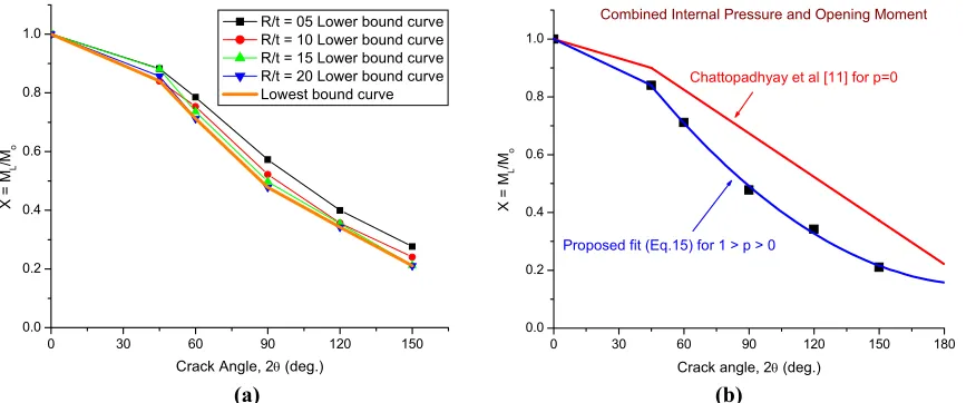
Figure 5 shows the effect of internal pressure on the PCM of TCC elbows subjected to combined internal pressure and opening bending moment. All the data points have been generated for long radius elbows (Rb/R= 3). It has been observed that for opening mode, the weakening factor (X) is not a strong function of internal pressure as in the case of closing mode.
Accordingly, on a conservative estimate, a lower bound curve of weakening factor (X)versus crack angle
(2θ) is plotted for each R/t. A two-part curve-fitting is done on this lowest bound curve and the proposed equations are as follows (see Fig.5):
1 1.2776
X = −
θπ for 0
o≤ 2θ≤ 45o (15)
2
1.3053 4.2133 3.8386
= −
+
θ θ
π π for 45
o < 2θ≤ 150o
Figure 5b compares the predictions of Eq.(15) for combined loading with that for pure in-plane opening moment loading. It may be noted from Fig.5b that internal pressure moderately increases the weakening effect (i.e. decreases the weakening factor X) of a throughwall circumferential crack at elbow intrados, compared to the pure in-plane opening moment loading (p = 0).
Throughwall Axially Cracked Elbow
0 30 60 90 120 150 0.0
0.2 0.4 0.6 0.8 1.0
X = M
L
/Mo
Crack Angle, 2θ (deg.)
R/t = 05 Lower bound curve R/t = 10 Lower bound curve R/t = 15 Lower bound curve R/t = 20 Lower bound curve Lowest bound curve
0 30 60 90 120 150 180
0.0 0.2 0.4 0.6 0.8 1.0
Combined Internal Pressure and Opening Moment
Proposed fit (Eq.15) for 1 > p > 0
Chattopadhyay et al [11] for p=0
X =
ML /Mo
Crack angle, 2θ (deg.)
(a) (b)
Fig.5 Variation of weakening factor (X) with int. pressure and crack angle (2θ) for TCC elbows: (a) Lowest bound curve for all R/t and p values, (b) comparison with un-pressurized case
Figure 6 shows the effect of crack on the PCM of TAC elbows subjected to closing bending moment. All the data points are generated for long radius elbows (Rb/R= 3). Axial crack size (2a) is normalized as crack angle (2α) using the following relation:
a = Rb.α (16)
where, Rb is the mean bend radius. Accordingly, the normalized crack size parameter (a/Dm) is expressed as:
a/Dm = (Rb/Dm).α (17)
Normalization of crack size using crack angle (α) is preferred here to the parameter (a/Dm), because α is independent of bend radius (Rb) which is not the case for ‘a/Dm’. Figure 6 also compares the present results with the predictions by Zahoor [12]. It may also be observed from Fig.6 that the weakening factor (X) of short radius elbows as predicted by Zahoor [12] is closer to the present results.
0 10 20 30 40 50
0.0 0.2 0.4 0.6 0.8 1.0
Symbols: Present FE results Solid lines: Proposed fit
Zah oor [14],
Long ra dius elb
ow
Zahoor [14], Short radius elbow
20
1510
R/t = 5
Proposed fit: X = ML/Mo = 1.0 - 2.11(α/π) + 1.958(α/π)0.8855/(R/t)0.2346
X = M
L
/M
o
Semi axial crack angle, α (deg.)
0 5 10 15 20 25 30 35 40
0.0 0.2 0.4 0.6 0.8 1.0
X = M
L
/ M
o
Semi axial crack angle (α) p = 0 p = 0.1 p = 0.2 p = 0.4 Closing Moment (R/t = 5)
(a) (b)
Fig.6 Variation of normalized plastic collapse moment with axial crack angle for closing moment for: (a) pure closing moment (b) combined int. pressure and closing moment
0.8855
0.2346 1.958 1.0 2.11
X
R t
= − +
αα π
π Applicability: 5 ≤R/t≤ 20, 0 ≤2α< 90
o, 2 ≤ (R
b/R)≤ 3 (18)
To investigate the effect of internal pressure on the weakening factor (X) for TAC elbow under closing moment, a systematic study is carried out where, the above set ofTAC elbowshave been analyzed under combined internal pressure and bending moment loading. It has been observed that the effect of internal pressure on the X vs.
α variation is negligible. Therefore, Eqs.(6,8,18) may be used even for combined loading of internal pressure ( p ≤
0.4) and in-plane closing moment without losing much accuracy in a conservative manner.
Following the same procedure for opening bending moment, the proposed equation of weakening factor is as follows:
1.6215
0.2441 4.1787 1.0
X
R t
= −
απ Applicability: 5 ≤R/t≤ 20, 0 ≤2α< 80o, 2 ≤ (R
b/R)≤ 3 (19)
DEVELOPMENT OF ELASTIC-PLASTIC J AND COD ESTIMATION SCHEME FOR THROUGHWALL CIRCUMFERENTIALLY CRACKED ELBOW UNDER IN-PLANE BENDING MOMENT
LBB qualification of nuclear power plants requires detailed fracture analysis of piping components with postulated throughwall cracks. For this purpose, the estimation of elastic-plastic J-integral and COD is very essential. In LBB analyses, J-integral is used to calculate crack initiation and unstable ductile tearing load while COD is used to calculate crack opening area in the evaluation of leakage size crack. Elastic-plastic finite element analysis (FEA) is the most general technique to evaluate these parameters. However, FEA often requires large computational time, expertise and resources, which make the computation quite expensive. Moreover, it has to be carried out on a case-by-case basis for each piping component. To circumvent these problems, simple J and COD estimation schemes emerged. However, J and COD estimation schemes for cracked elbows, one of the very important geometry for LBB analyses is quite limited. In the present paper, simple J and COD estimation schemes for elbow with throughwall circumferential crack at extrados/intrados subjected to in-plane closing/opening bending moment have been proposed. The following paragraphs describe very briefly the methodology followed to develop the estimation schemes. More details may be found in [13-15].
Methodology
Non-linear finite element analysis is carried out to determine the J-integral and COD of throughwall
circumferentially cracked (TCC) elbows for various geometric and material combinations. Incremental flow theory of plasticity considering both geometric and material non-linearties is adopted in the present analysis. The crack is located at extrados and intrados for closing and opening bending moment respectively. Material stress-strain properties are assumed to follow Hook’s law up to yield stress and beyond yield stress, to follow Ramberg-Osgood relation. The equations are as follows:
y y
ε
σ
ε
=
σ
for σ≤σy andn
y y y
ε
σ
α
σ
ε
σ
σ
=
+
forσ > σy (20)
where, σ is the true stress, ε is the true strain, σy, σy, αand n are the yield strain, yield stress, Ramberg-Osgood coefficient and hardening exponent respectively with Eεy = σy, where, E is the Young’s modulus. The values for some of these parameters have been fixed as: E = 200 GPa, α = 1, σy = 300 MPa and ν = 0.3, where, ν is the Poisson’s ratio. However, specific values of these parameters do not affect the estimation schemes. The Ramberg-Osgood hardening exponent (n) has been varied as: n = 3,5,7, which cover a wide range of steel material.
There is no solution available for elastic COD of TCC elbow subjected to in-plane bending moment. Accordingly, it has been developed here. The equation of elastic COD is as follows:
2
2
4
e o MV
D E
=
δ
π (21)
where, Do is the outer diameter of elbow cross section, V2 is a parameter which depends on R/t and crack angle (2θ). The V2 parameter is calculated from the initial few elastic load steps for each geometry. It is calculated separately for COD at inside and outside surface and for all combinations of R/t and 2θ. The plastic component of J-integral and COD are obtained from FEA as follows:
Jp = JFE – Je andδp = δFE - δe (22)
where, JFE and δFE are the total J-integral and COD respectively obtained from FEA and J
eand δe are their elastic components. The plastic components of J-integral and COD for throughwall circumferentially cracked pipe subjected to bending moment are, in general, expressed as follows [12]:
1 2
1 1
n
p y y
L M
J R h
M
+
=
−
θ ασ ε π
π and 2
n
p y
L M Rh
M
=
δ αε π (23)
where, M is the applied moment, ML is the limit moment which is proportional to σy, α and n are the constants in Ramberg-Osgood Eq.(20), h1 and h2 are the non-dimensional plastic influence functions which ideally depend only on R/t, n and 2θ .
The same form is retained in this paper for plastic components of J-integral and COD for TCC elbow subjected to in-plane closing/opening moment.
Proposed J and COD estimation schemes
The geometry constants and also the plastic influence functions i.e. h1for J-integral in Eq.(23) and h2 for COD at inside and outside surface in Eq.(23) are evaluated for various geometric cases and Ramberg-Osgood hardening index, n = 3,5,7. Detailed values of these constants are available in [12-15]. The proposed J-integral and COD equations are as follows:
J = Je + Jp ; δ = δe + δp ; Je = K2 / E
1
1 2
1
1
1 , ,
n
n
p y y
L
R M
J R h n
t M
+ +
=
−
θ θ
α σ ε π
π π
for
L ≤1.0M
M
(24)
α1/(n+1) in the above eqn. is replaced with α for M/M
L≥ 1.2 and it is linearly interpolated for 1.0 < M/ML < 1.2
1
2 , ,
=
n n
p y
L
R M
Rh n
t M
θ δ α ε π
π
for
L ≤1.0M
M
(25)
α1/n in the above eqn. is replaced with α for M/M
L≥ 1.2 and it is linearly interpolated for 1.0 < M/ML < 1.2 where, the subscripts ‘e’ and ‘p’ indicate the elastic and fully plastic values respectively, ML is the limit moment.
CONCLUSIONS
REFERENCES
1. Chattopadhyay,J., Dutta,B.K. and Kushwaha,H.S., “Experimental and analytical study of three point bend specimens and throughwall circumferentially cracked straight pipe”, International Journal of Pressure Vessels and Piping, Vol.77, 2000, pp 455 – 471
2. Chattopadhyay,J., Pavankumar,T.V., Dutta,B.K. and Kushwaha,H.S., “Fracture experiments on throughwall cracked elbows under in-plane bending moment: Test results and theoretical/numerical analyses”, Engineering Fracture Mechanics, Vol.72, 2005, pp 1461 – 1497
3. Rice,J.R., Paris,P.C. and Merkle, J.G., 1973, “Some Further Results of J-integral Analysis and Estimates”,
Progress in Flaw Growth and Fracture Toughness Testing, ASTM STP 536, American Society for Testing and Materials, Philadelphia, pp 231 – 245
4. Ernst,H.A., Paris,P.C., Rossow,M. and Hutchinson,J.W., 1979, “Analysis of Load Displacement Relation to Determine J-R Curve and Tearing Instability Material Properties”, Fracture Mechanics, ASTM STP 677, C.W. Smith, Ed.,American Society for Testing and Materials, Philadelphia, pp 581 – 599
5. Ernst,H.A. and Paris,P.C., “Techniques of Analysis of Load-Displacement Records by J-integral Methods”, NUREG/CR-1222, US Nuclear Regulatory Commission, , 1980
6. Chattopadhyay,J., Dutta,B.K. and Kushwaha,H.S., “Derivation of γ parameter from limit load expression of cracked component to evaluate J-R curve”, International Journal of Pressure Vessels and Piping, Vol.78, 2001, pp 401 – 427
7. Chattopadhyay,J., Dutta,B.K. and Kushwaha,H.S., “New ‘ηpl’ and ‘η’ functions to evaluate J-R curves from cracked pipes and elbows: Part I – Theoretical derivation”, Engineering Fracture Mechanic, Vol.71, Issue no.18, 2004, pp 2635 - 2660
8. Chattopadhyay,J., Dutta,B.K. and Kushwaha,H.S., “New ‘ηpl’ and ‘η’ functions to evaluate J-R curves from cracked pipes and elbows: Part II –Experimental and numerical validation”, Engineering Fracture Mechanics, Vol.71, Issue no.18, 2004, pp 2661 – 2675
9. Clausmeyer, H., Kussmaul, K. and Roos, E., Influence of stress state on the failure behaviour of cracked components made of steel, ASME, Applied Mechanics Rev., Vol.44 (2), 1991, pp77-92.
10. T.V.Pavankumar, Chattopadhyay,J., Dutta,B.K. and Kushwaha,H.S. “Importance of stress triaxiality at crack tip in elastic-plastic fracture mechanics”, 8th International Symposium on Plasticity and Impact Mechanics,
IMPLAST 2003, 16-19th March, , New Delhi, India, 2003
11. Chattopadhyay,J., Kushwaha,H.S. and Roos,E., “Improved Integrity Assessment Equations of Pipe Bend”, Int. J. of Pressure Vessel and Piping, Vol.86, 2009, pp 454 - 473
12. Zahoor,A., 1989-1991, “Ductile Fracture Handbook”, Vol.1-3, EPRI-NP-6301-D, N14-1, Research Project 1757-69, Electric Power Research Institute
13. Chattopadhyay,J.,Tomar, A.K.S., Dutta, B.K., and Kushwaha, H.S., “Elastic-plastic J and COD estimation schemes for throughwall circumferentially cracked elbow under in-plane closing moment”, Engineering Fracture Mechanics, Vol.72, 2005, pp 2186 - 2217
14. Chattopadhyay,J., Acharyya, S., Kushwaha, H.S., “Elastic-plastic J and COD estimation schemes for 90o elbow
with throughwall circumferential crack at intrados under in-plane opening moment”, International Journal of Fracture, Vol.144, No.4, pp 227 - 245, 2007