1
FATIGUE CRACK GROWTH BEHAVIOUR OF RAFM STEEL IN PARIS
AND THRESHOLD REGIMES AT DIFFERENT TEMPERATURES
M. Nani Babu, G. Sasikala*, B Shashank Dutt, S Venugopal, A. K. Bhaduri, T. Jayakumar
Metallurgy and Materials Group, Indira Gandhi Centre for Atomic Research, Kalpakkam, India- 603 102 *E-mail of corresponding author: gsasi@igcar.gov.in
ABSTRACT
Fatigue crack growth (FCG) behaviour of a reduced activation ferritic martensitic (RAFM) steel has been evaluated at 300, 653 and 823 K and the effect of temperature in Paris and threshold regimes have been discussed. The FCG results were compared with EUROFER 97. The effect of temperature on thresholds and associated crack closure mechanisms are highlighted. Finally, crack tip effective stress intensity factor ranges ( Ktip,eff) have been evaluated
by taking crack tip shielding into account.
INTRODUCTION
Reduced Activation Ferritic/Martensitic (RAFM) steel is chosen for fusion reactor first wall and blanket applications [1-3]. The focus of RAFM steel is to reduce the environmental impact of the irradiated steel after the service lifetime of a fusion reactor. This is achieved by selective substitution of highly radioactive (induced) elements Mo by W and Nb by Ta. The ferritic- martensitic structure offers excellent void swelling resistance too, when compared to the austenitic stainless steels. India has chalked out a long-term programme for the development of RAFM steel. In the first phase of the programme, efforts have been made to develop a RAFM steel conforming to EUROFER 97 to demonstrate the capability of Indian steel industry, for producing the steel with close control on the chemical composition, inclusion content and with specified physical and mechanical properties. International efforts to develop RAFM steel have focused on varying tungsten in the range 1–2 wt.% and tantalum in the range 0.02–0.18 wt.% [4-6]. Tungsten addition increases creep rupture strength but also increases DBTT [7]. Tantalum in the RAFM steel leads to prior-austenitic grain size refinement [8] thereby lowering the DBTT, however, decreasing the weldability [9]. Hence, the second phase of this programme aims to optimize the composition, especially with respect to tungsten and tantalum contents from considerations of fracture toughness, creep strength and weldability. This optimized composition is designated as India-specific RAFM steel and the steel produced in large scale is used for detailed characterization of physical and mechanical properties and weldability for validation of the material in the third phase.
For the damage assessment and structural integrity of these components, the fatigue crack growth (FCG) and fracture toughness properties are necessary. The mechanical properties and influence of specimen geometry for similar grade (RAFM) steels are available in literature [10-12]. Also, the effects of irradiation and hydrogen on mechanical properties have been examined [13-15]. The
tensile, dynamic and quasistatic fracture toughness
of an indigenously produced RAFM steelhav
e been evaluated [16, 17]. A campaign was initiated to study the FCG behaviour of indigenously developed RAFM steel at different temperatures in comparison with those for the international grades.The fatigue crack growth rate (
da
dN
) is related to the stress intensity factor range,K
K
maxK
min, the difference of (Kmax) maximum and (Kmin) minimum applied stress intensities. For intermediate crack growth rates,these are correlated using the Paris equation [18]. n
K
C
dN
da
--- (1)where the coefficient,
C
, and the exponent,n
, are material constants. This regime is generally considered to be insensitive to microstructure, environment and load ratio (R =K
minK
max) and sensitive to temperature. AsK
is gradually reduced, the crack growth rate drastically decreases, approaching a threshold valueK
th at whichdN
2
closure, overloads, cold work etc are found to influence
K
th; in addition,K
th is sensitive also to the method of measurement, and specimen geometry [20-23]. In the FCG studies on RAFM steels reported in literature, [10-15] the effect of crack closure on fatigue crack growth has not been considered explicitly, and thus it may lead to the over estimation of the fatigue life of the components made up of the RAFM steel. When crack closure is accounted for, K can be written as Keff = Kmax Kcl, where Kcl is stress intensity factor corresponding to the closure load.The present paper focuses on fatigue crack growth behaviour of the RAFM steel at 300, 653 and 823 K in Paris and threshold regimes. The influence of temperature on FCG in Paris regime, and crack closure effects in threshold regimes have been examined. The crack tip shielding due to different shielding mechanisms have been addressed.
EXPERIMENTAL
Materials and Specimen Preparation
The RAFM steel in the present study was available in the form of plates of 25 mm thickness in the normalized (1253 K for 30 min) and tempered (1033 K for 60 min) condition (NT). The chemical composition is given in Table 1. CT specimen blanks of approximate dimensions of 70 65 25 mm were cut from the plate. 20 mm thick compact tension CT specimens were fabricated from these blanks with the notch made using electric discharge machine (EDM). A schematic view of the CT specimen is shown in Fig. 1(a). The typical microstructure of the material in NT condition consists of tempered martensite as shown in Fig. 1(b).
(a) (b)
Fig 1. (a) CT Sample (b) microstructure of RAFM steel
Table 1. Chemical composition of the RAFM steel
Fatigue Crack Growth Test
The FCG tests were conducted at ambient temperature (300 K), 653 K and 823 K in air according to ASTM E647 [19] at a constant R value of 0.1 and load frequency of 15 Hz in a fully automated servo hydraulic machine. Crack length measurements were carried out using a suitably calibrated direct current potential drop (DCPD) system. Specifically, the tests employed were
K
decreasing type, withK
values being progressively reduced as the crack grows during the test as prescribed by the ASTM standard [19]. asK
K
0exp(
c
.
a
)
. HereC Mn Cr V W Ta N B Ti Nb Mo Ni Fe
3
0K
is the value ofK
at the start of the test, the normalised K gradient, C which is set to 0.08 mm 1 anda
isthe crack growth.
Determination of Opening/Closure loads
The loads at which crack opens fully in the loading part of the cycle or starts closing in the unloading part,
P
opand
P
cl respectively, have been determined from the load (P) –displacement ( ) data. Generally, a few slow cycles are employed to collect the P- data for this. However, in the present case, a slow ramp from minimum load (Pmin) tomaximum load (Pmax) and back was used in order to acquire data at closer intervals, rendering the determination of
the opening or closure loads more accurate even at high temperature with COD gages of lower stiffness.
RESULTS AND DISCUSSION
The FCG results of RAFM without and with closure correction at 300, 653 and 823 K are presented in Figs. 2 (a & b) respectively. Effect of temperature and different closure mechanisms on the FCG behaviour in both Paris and thresholds regimes have been discussed in the following sections.
Fig. 2: FCG of RAFM different temperatures (a) without and (b) with closure correction
Fatigue crack growth in Paris regime
Paris parameters
Paris law can be used to quantify the residual life of a component, given with a particular crack size. The Paris constants C and n obtained using the K and Keff for the three temperatures are presented in Table 2. (It may
be noted that da/dN in nm/cycle was used to obtain the C values presented.) When K is used for correlation, both these parameters show significant variations with temperature. The variations in C and n are found to be complimentary to each other without crack closure. However, when the closure correction was incorporated, i.e., when Keff is used for correlations, n decreases from 300 to 823 K, while C decreases at 653 K followed by increase.
Table 2: The FCG parameters for RAFM steel at the three temperatures
4 5 6 7 8 9 10 20 30
1 10 100 1000
(b)
Material : RAFM Load ratio : 0.1 Frequency :15Hz
300 K 653 K 823 K
d
a
/d
N
, nm/
c
y
c
le
K
eff
, MPa.m
1/24 5 6 7 8 9 10 20 30
1 10 100 1000
(a)
Material : RAFM steelLoad ratio : 0.1 Frequency : 15Hz
da/
dN. n
m/cy
c
le
K, MPa.m
1/24
Temperature,K
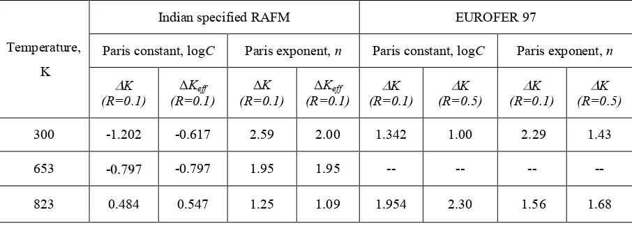
Indian specified RAFM EUROFER 97
Paris constant, logC Paris exponent, n Paris constant, logC Paris exponent, n K
(R=0.1) (R=0.1)ΔKeff (R=0.1)ΔK (R=0.1)ΔKeff (R=0.1)K (R=0.5)K (R=0.1)K (R=0.5)K
300 -1.202 -0.617 2.59 2.00 1.342 1.00 2.29 1.43
653 - -0.797 1.95 1.95 -- -- -- --
823 0.484 0.547 1.25 1.09 1.954 2.30 1.56 1.68
Fatigue crack growth in threshold regime
Crack closure effects, which are expected to be more significant in the threshold regime, would influence the ΔKth determined. Further, the extent and mechanism of closure can be different at different temperatures [24],
and the temperature-dependence of the intrinsic FCG threshold can be masked by these effects. Therefore, the threshold stress intensity (ΔKth) and effective threshold stress intensity (ΔKeff,th) factor range for different
temperatures presented in Table 3, are examined. It is interesting to note that the anomaly in ΔKth with temperature
i.e higher ΔKth at 823 K. However, this anomaly is removed after incorporating closure correction, as seen in the
temperature-independent in ΔKeff,th . From Table 3, it may be seen that the Kth decreases with temperature up to 653
K and further increase in temperature (823 K) resulted in slight increase in Kth to that of at 653 K. The extents of
closure in the threshold regime at the three temperatures are also indicated in Table 3. The mechanisms of crack closure at different temperatures and the reasons for the enhanced variations in ΔK,th are discussed in the following
sections.
Table 3. FCG thresholds at different temperatures Temperature,
K
Threshold SIFs, MPa.m1/2
(RAFM) ΔKth - ΔKeff,th
MPa.m1/2
EUROFER 97*[15] ΔKth(R=0.1) ΔKeff,th(R=0.1) Kth (R=0.1) Kth (R=0.5)
300 7.80 5.65 2.15 9.02 4.73
653 5.56 5.36 0.20 -- --
823 7.02 5.24 1.78 6.98 5.21
Comparison of Indian specified RAFM and EUROFER 97
The FCG parameters of RAFM and EUROFER 97 [15] are presented in Table 2 and 3 in order to compare in both Paris and threshold regimes respectively. The Paris exponents of RAFM and EUROFER 97 at a load ratio of 0.1 and temperature 300 K are comparable without and with crack closure correction. However, the Paris exponent (n) and constant (C) of EUROFER 97 at higher temperature showed higher irrespective of load ratios (Table 1) indicating that the lower FCG resistance. Thus it may be inferred that the FCG resistance of Indian RAFM is superior to that of EUROFER 97 in the Paris regime at higher temperature (823 K). One the other hand the Kth of
both the materials is in the same order at 300 and 823 K, at a load ratio of 0.1. At higher load ratios (0.5) where the closure effects expected to be low, the Kth of EUROFER 97 is found to be lower than that of the ΔKeff,th (after
closure correction) of RAFM tested at lower load ratios. The lower ΔK,th of EUROFER 97 at a load ratio of 0.5
5
influence on the FCP parameters. Therefore, the crack closure should be taken in to account at the time of design against fatigue damage.
Crack closure mechanisms
Various closure mechanisms like plasticity induced closure (PIC), roughness induced closure (RIC), oxide-induced closure (OIC) etc, have been established in the literature [21]. These closure effects becomes more significant as K decreases and influences the threshold determination as has been observed in numerous studies on crack closure behavior [21].The variations in thresholds are examined considering the closure contribution, which are 2.15 and 1.78 MPa.m1/2 at 300 and 823 K respectively, while it is only 0.20 MPa.m1/2 at 653 K. The high closure
contributions at 300 K may be due to the roughness (Fig. 4(a)), at 653 K which is low as can be seen Fig 4(b). On the other hand, at 823 K, the fracture surface appears quite smooth (Fig 4(c)) and it appears that there cannot be any RIC in this condition. The increase in the value of closure contribution at 823 K might have resulted from other mechanisms such as OIC or PIC, as expected and there is also heavy oxidation along the crack path (Fig 4(c)).
Fig. 4. Optical micrographs showing decreasing crack path tortuosity with test temperature (a) 300 K (b) 653 K (c) 823 K.
The possibility of PIC needs to be examined. PIC, as a first approximation, is proportional to the plastic zone size [25] which in turn depends inversely on the yield stress, rp = (1/2 )(Kmax/ y)2 for plane stress condition.
Therefore, the PIC is expected to increase with increasing temperature. However, the closure contribution in the present study is lower at 653 K, and it increases with further increase in temperature to 823 K. Lowering of the fracture surface roughness can be attributed to the change in slip character form planar at 300 to wavy at 823 K. This is consistent with observations of the decrease in the crack path tortuousity with the temperature Fig 4(a-c). After the closure correction the anomaly in the ΔK,th removed and the Keff,th found to be insensitive to the temperature. In
addition the tensile properties indicated the predominance of dynamic strain ageing (DSA) at 653 K. Table 4 Tensile properties of RAFM steel at different temperatures
Test temperature
(K)
Yield strength (YS),MPa
Tensile strength (UTS), MPa
% elongation
(EL) % Reduction in area (RA)
300 630 750 9 50
653 540 613 7 49
6
Crack tip shielding
The above discussion considers Keff as the driving force for fatigue crack growth. In ceramics,
intermetallics, and composites, improved crack growth resistance due to crack tip stress shielding by various phenomena like bridging, interlocking and branching of the cracks has been observed. In such cases, the crack tip stress intensity factor range Ktip rather than Keff is considered to be more appropriate as the driving force for crack
growth. The effect of crack tip stress shielding on the fatigue crack growth behaviour of SS 316 (N) weld with duplex microstructure has been examined [24]. In the present study too, deviations and branching of the cracks have been observed. Therefore, the possible effects of crack tip shielding on the observed FCG behaviour has been examined following the lines of a previous study [26,27]. The crack tip stress intensity factor Ktip is given as Ktip =
Kmax − Ks where Kmax is the maximum stress intensity factor without the stress shielding effect and Ks is the stress
intensity factor corresponding to stress shielding effect. It is difficult to estimate the Ks value under the complicated
fatigue crack growth processes. In this study, Ktip was experimentally evaluated by measuring the crack-mouth
opening-displacement, as mentioned by Suresh [21]. Combining the two equations for stress intensity factor and crack mouth opening-displacement (δ) [24], the relationship between Ktip and δdeal, the crack-mouth
opening-displacement expected for ideal cracks without stress shielding, can be obtained as
W
W
a
V
W
a
F
E
K
idealtip
(
/
(
)
/
)
(2)where F and V are polynomial functions, and
E
'
E
(
1
v
2)
where E is the Young’s modulus and is the Poisson’s ratio. For a given crack length, it is known that a linear relationship between Kmax and δideal as followsmax
K
ideal (3)Here, as a first stage of approximation, a similar relationship is assumed to exist between Ktip and δexp, δ measured
during fatigue crack growth tests, which includes the stress shielding effect. That is,
erimental tip
K
exp (4)max
exp
K
K
ideal erimental
tip (5) and
K
tip,effK
tipK
cl (6)where Kcl is the crack closure stress intensity factor. The results obtained using relationship between Ktip,eff and
da/dN are presented in Fig. 6. The values of Ktip,eff,th were 1.19, 0.69 and 0.84 MPa.m1/2 at 300, 653 and 823 K,
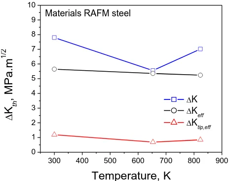
respectively. The three thresholds at different temperatures have been presented in Fig. 7 for easy comparison. It is obvious from Fig. 7, that variation in Ktip,eff,th are much lower when compared to other thresholds, indicating the
lower sensitivity of Ktip,eff,th to temperature. It is worth noting here that the relatively higher intrinsic FCG
resistance at 823 K, compared to 653 persists even with shielding effects accounted for, suggesting the role of DSA. However, the intrinsic crack tip shielding by dislocations around the crack tip needs to be studied further.
Fig. 6 : Effect of crack tip stress on the FCG at different temperatures
0.6 0.8 1 2 4 6 8 10 20
1 10 100
Material : RAFM Load ratio : 0.1 Frequency :15Hz
d
a
/d
N
, nm
/cy
c
le
K
tip,eff, MPa.m
1/27
Fig. 7 :Effect temperature on different thresholds.
5.0 CONCLUSIONS
FCG behaviour of RAFM was evaluated at 300, 653 and 823 K in both Paris and thresholds regimes without and with crack closure correction.
K
this found to be 7.80, 5.56 and 7.02 MPa.m1/2 and Keff,th is 5.65,
5.36 and 5.24 MPa.m1/2 at 300, 653 and 823 K, respectively. The anomaly in K
,th has been removed by
incorporating the crack closure effects. The RIC was predominant at 300 and, while at 823 K the OIC, PIC and RIC were minimal at 653 K. The FCG results of RAFM were compared with the EUROFER 97. It is inferred that the FCG resistance of RAFM in the Paris regime is superior to that of EUROFER 97 at higher temperature. In addition the decrease in the crack closure with temperature is attributed to the change on the slip character from planar to wavy at 653 K. Moreover, the increase in the intrinsic crack growth resistance is due to the conjoint influence of cyclic hardening (DSA) and softening due to rearrangement of dislocation at 823 K. The values of Ktip,eff,th 1.19,
0.69 and 0.84 MPa.m1/2 at 300, 653 and 823 K, respectively.
ACKNOWLEDGEMENTS
The authors wish to acknowledge Director, IGCAR for encouragement and support. We wish to thank Smt. G. Shanthi and Mr. Syed Meer Kaleem for experimental assistance
REFERENCES
[1] R.L. Klueh and D.R. Harries. , ASTM Mono3, West Conshohocken, PA (USA) (2001).
[2] N. Baluc, R. Schaublin, P. Spatig and M. Victoria, On the potentiality of using ferritic/martensitic steels as structural materials for fusion reactors, Nucl. Fusion 44 (2004) 56–61.
[3] WANG Pinghuai, NOBUTA Yuji, HINO Tomoaki, YAMAUCHI Yuji, CHEN Jiming , XU Zengyu , LI Xiongwei, LIU Shi, Helium Retention and Desorption Behaviour of Reduced Activation Ferritic/Martenstic Steel, Plasma Sci. Tech. 11 (2) (2009) 225-230.
[4] R. Lindau and M. Schirra, First results on the characterisation of the reduced-activation-ferritic-martensitic steel EUROFER, Fusion Eng. Des.58–59 (2001) 781–785.
[5] A. Alamo, J.C. Brachet, A. Castaing, C. Lepoittevin and F. Barcelo, Physical metallurgy and mechanical behaviour of FeCrWTaV low activation martensitic steels: Effects of chemical composition, J. Nucl. Mater. 258–263 (1998) 1228– 1235
300 400 500 600 700 800 900
0 1 2 3 4 5 6 7 8 9 10
Materials RAFM steel
K
Keff
Ktip,eff
K
th, MP
a.m
1/
2
8
[6] Y. Li, Q. Huang, Y. Wu, T. Nagasaka and T. Muroga, Mechanical properties and microstructures of China low activation martensitic steel compared with JLF-1, J. Nucl. Mater. 376–370 (2007) 117–121 [7] F. Abe, T. Noda, H. Araki and S. Nakazawa, Alloy composition selection for improving strength and
toughness of reduced activation 9Cr-W steels, J. Nucl. Mater. 179–181 (1991) 663–666.
[8] L. Schaefer and M. Schirra, Influence of thermal aging on tensile and impact bending properties of the steel grades OPTIFER and F82H mod., J. Nucl. Mater. 271–272 (1999) 455-458.
[9] T. Hasegawa, Y. Tomita and A. Kohyama, Influence of tantalum and nitrogen contents, normalizing condition and TMCP process on the mechanical properties of low-activation 9Cr–2W–0.2V–Ta steels for fusion application J. Nucl. Mater. 258–263 (1998) 1153–1157
.
[10] S.W. Kim, A. Kohyama, H.K. Yoon, Fatigue crack growth behavior and microstructure of reduced activation ferritic/martensitic steel (JLF-1), Fusion Eng. Des. 81 (2006) 1105–1110.
[11] Shuhei NOGAMI, Yuki SATO and Akira HASEGAWA, Fatigue Life Assessment Based on Crack Growth Behavior in Reduced Activation Ferritic/Martensitic Steel, J Nucl. Sci. Tech. 47 (5) (2010) 457–461.
[12] Shuhei Nogami, Yuki Sato, Akira Hasegawa, Hiroyasu Tanigawa, Masanori Yamazaki, Minoru Narui, Effect of specimen shape on micro-crack growth behavior under fatigue in reduced activation ferritic/martensitic steel, J Nucl. Mater. doi:10.1016/j.jnucmat.2010.12.048
[13] Yoshiharu Murase, Johsei Nagakawa, Norikazu Yamamoto, Effects of implanted hydrogen on fatigue behavior of F82H under irradiation, doi:10.1016/j.jnucmat.2010.12.049.
[14] C. Liu, H. Klein, P. Jung, Embrittlement of RAFM EUROFER97 by implanted hydrogen J. Nucl. Mater. 335 (2004) 77-82.
[15] J. Aktaa, M. Lerch, Near-threshold fatigue crack behaviour in EUROFER 97 at different temperatures, J Nucl. Mater 353 (2006) 101–108
[16] Baldev Raj, T. Jayakumar Development of Reduced Activation Ferritic–Martensitic Steels and fabrication technologies for Indian test blanket module, doi:10.1016/j.jnucmat.2011.02.032
[17] B. Shashank Dutt, M. Nani Babu, S. Venugopal, G. Sasikala, A. K. Bhaduri, Fracture toughness characterisation of RAFM steel, Proc. International conference on Advanced Nuclear Materials-2011, 09-11, February 2011, Mumbai, India, CD-ROM, Paper No. 63
[18] P.C. Paris, M, Gomez, and W. Anderson., A rational analytic theory of fatigue, Trend. Engg. 13 (1961), 9-14
[19] E647-08e1, Annual Book of ASTM Standards, ASTM, PA, USA, 2010
[20] W. Elber. Fatigue crack closure under cyclic tension, Engg. Fract. Mech. 2(1970)37-45. [21] S. Suresh. Fatigue of Materials, Cambridge University Press, 1991.
[22] R.O. Ritchie, Mechanisms of fatigue crack propagation in metals, ceramics and composites: Role of crack tip shielding, Mater. Sci. Eng. A 103 (1988) 15–28.
[23] R.O. Ritchie, C.J. Gilbert, J.M. McNaney, Mechanics and mechanisms of fatigue damage and crack growth in advanced materials, Intl. J. Solids and Stru. 37 (2000) 311-329.
[24] M. Nani Babu, B. Shashank Dutt, S. Venugopal, G. Sasikala, A.K. Bhaduri, T. Jayakumar, Baldev Raj, On the anomalous temperature dependency of fatigue crack growth of SS 316(N) weld, Mater. Sci. Eng. A 527 (2010) 5122–5129.
[25] Vibhor Chaswal , G. Sasikala, S.K. Ray, S.L. Mannan, Baldev Raj, Fatigue crack growth mechanism in aged 9Cr–1Mo steel: threshold and Paris regimes, Mat. Sci. Eng. A 395 (2005) 251–264.
[26] Y. Mutoh, Akhmad A. Korda, Y. Miyashita, T. Sadasue, Stress shielding and fatigue crack growth resistance in ferritic–pearlitic steel, Mat. Sci and Eng A 468–470 (2007) 114–119.