Dynamic Analysis of RCC Frame Structures
with and Without Viscous Damper Having
Different Aspect Ratio
Vibha More1, Dr. Vikram Patil2,Somanagouda Takkalaki31
Civil Engineering, B.R.Harne College of Engineering & Technology, Mumbai, Maharashtra 421503, India
2
Civil Engineering, B.R.Harne College of Engineering & Technology, Mumbai, Maharashtra 421503, India
3
Civil Engineering, B.R.Harne College of Engineering & Technology, Mumbai, Maharashtra 421503, India
Abstract
Damping plays vital role in design of Earthquake Resisting Structure, that reduces the response of the structure when they are subjected to lateral loads. There are many different varieties of damper in use. In the present study, Fluid Viscous Damper (FVD) are used to evaluate the response of RCC building.
The main task of a structure is to bear the lateral loads and transfer them to the foundation. Since the lateral loads imposed on a structure are dynamic in nature, they cause vibrations within the structure. In order to have earthquake resistant structure, fluid viscous damper have been used. Models having three different aspect ratio with two story height are analysed with four different damper locations and without FVD. Individual model was created in ETABS for analysis of damper and to carry out different result such as story displacement, story drift and modal period. Using Response Spectrum Analysis the responses of RCC model are considered in the present study.
Keywords: Dynamic analysis, dampers, Aspect Ratio, Etabs version 15.
1. Introduction
Earthquakes are one of man’s most feared natural phenomena. Major earthquakes producing instantaneous destruction of building and other structure. The damage caused by earthquake is almost entirely associated with man made structure such as Buildings, Dams, Bridges and other works of man.
Unfortunately, many of earthquakes give very little or no warning before occurring and this is one of the reason why earthquake engineering is complex.
On average about 200 large magnitude earthquakes occur in each decade. About 10%-20% of these earthquake occur mid-ocean and hence cause no problem in human settlement.
No engineer can truly transform badly conceived building
into an earthquake resisting building. Simplicity, Regularity and symmetry in both elevation and plan are the ideal aspects of the building. These properties are important to predict the forces and distribution of forces in structure while irregular structure causes increase in dynamic response at certain location of structure. Also, buildings which are tall as compared to their plan area will generate high overturning moment while building with large plan area may act differently.
2. Techniques to Resist Earthquake
Conventional methods such as base widening or providing heavy massive structure at bottom has been used in the past for resisting earthquake forces and to minimise the wind effect .These conventional method can not be used for modern high rise buildings and tall structures.
More advanced techniques for earthquake resistance is not to strengthen the building, but to reduce the earthquake-generated forces acting upon it.
Among the most important advanced techniques of earthquake resistant design and construction are:
• Base isolation technique.
• Energy dissipation devices (Damper).
1.1.1 Base Isolation Technique
Base isolation is a state-of-the-art method in which the superstructure is separated from the foundation or substructure by introducing a suspension system between the base and the main structure.
1.1.2 Energy Dissipation Devices (Damper)
1.1.2.1 Passive Control Devices
A device that develops forces at the location of the device by utilizing the motion of the structure is known as Passive Control Device. Examples of passive devices include friction dampers, metallic yield dampers, viscous fluid dampers, tuned mass dampers (TMD), tuned liquid dampers (TLD).
1. Viscous Damper :
Viscous dampers offer an alternative to structural yielding or failure as a way to absorb earthquake energy. Viscous dampers can absorb almost all the earthquake energy, leaving the structure intact and ready for immediate use after an event. Viscous dampers
provide a force that always resists structure motion.
Fig. 1 : Longitudinal Section of Viscous Damper
In a correctly designed and fabricated viscous damper there is nothing to wear out or deteriorate over time so there is no practical limit on expected life. Warranty periods of 35 years are common.
3. Objective and Scope
1.
The main objective of this project is to understand the behaviour of R.C.C. structures analytically with and without FVD.2.
To find out the change in the values of various structural parameters like Storey Displacement, Storey Drift and Time Period using Response Spectrum Analysis.3.
To find out the optimised location for the dampers in the structure. So, it gives maximum reduction in the structure response.For satisfying above mentioned objectives following points were studied
Detailed analytical study on fluid viscous damper using ETABS version 15.
The study is limited to analysis of 20 storey and 40 storey of R.C.C. building.
Total four different structures are modelled for two different height and two varying Aspect Ratio.
4. Methodology
One of the basic needs in a structural design is to reliably predict the desired structure under specified loading condition. In designing structures with added various dampers, the most important design parameter is the property of damper. First the analysis of structure without dampers is carried out. Then the analysis of structure with four different damper location is carried out. The design will normally contain the subsequent steps which may continuously be updated to determine the structural properties once every design cycles.
4.1 Steps for design and analysis
a)
Determine structural properties of building and perform structural analysis under the earthquake load.b)
Study the response of the structure after analysis like storey displacement, storey drift, and Time period.c)
Determine the appropriate locations of the damper in the model.d)
Again analysis is carried out for model with no damper and also model with different damper locations.e)
Carried out the response of the structure like storey displacement, storey drift and Time period for individual model.f)
Compare the result of storey displacement, storey drift and Time period for with and without Damper.5. Problem Statement
The present work involves the study of structure with and without Fluid Viscous Damper . The various height will be consider for this study are 20 floors and 40 floors. Also different Aspect Ratio to be considered such as 1, 1.5. The aim of study is to find out the differences in various parameters of structure by using ETABS software by performing Response Spectrum Analysis.
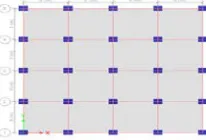
Fig. 3 : Model C & Model D with Aspect Ratio 1.5
Fluid Viscous Dampers will be installed in the building to combat the acceleration force due to earthquake. Trial and error method has been carried out to find the optimum location for the dampers in the building.
Table 1 : General Details of Structure
Particulars Model A
Model B
Model C
Model D
Aspect Ratio 1.0 1.0 1.5 1.5
Max.length in X-dir. 20 20 30 30 Max.length in Y-dir 20 20 20 20
No. of floors 20 40 20 40
Floor to floor height in m
3 3 3 3
Total height in m 60 120 60 120 Slab thickness 125 125 125 125 Earthquake Zone Zone
IV
Zone IV
Zone IV
Zone IV Seismic zone factor 0.24 0.24 0.24 0.24 Response reduction
factor
5 5 5 5
Importance Factor 1 1 1 1
Table 2 : Load Configuration
Description Loadings Self-weight As per Etabs LL 2 kN/m2 FF 1 kN/m2
Properties of Viscous Damper
Linear Fluid Viscous Damper [11] : Model No.17120 (From Taylor Devices) Force : 250 KN
Weight : 44 Kg
6. Results
The Models are :
Model (A,B,C,D) : Model without damper
Model (A.1,B.1,C.1,D.1) : Model with dampers in all external corners ( Diagonally)
Model (A.2,B.2,C.2,D.2) : Model with dampers in all external corners till 10th floor ( Diagonally)
Model (A.3,B.3,C.3,D.3) : Model with dampers in all external corners ( Zig-zag pattern)
Model (A.4,B.4,C.4,D.4) : Model with dampers in all external corners till 10th floor (Zig-zag pattern)
6.1 Storey Displacement :
Fig. 4 : Storey Displacement in Model A in X-direction
Fig. 5 : Storey Displacement in Model A in Y-direction
From figure 4 and 5 , we can see that fluid viscous damper reduces the storey displacement by 31% for model A.4 and also, by 20% for model A.3 when compared with model A in X-direction and Y-direction.
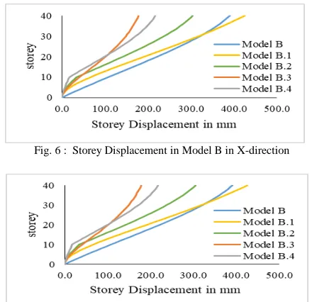
Fig. 6 : Storey Displacement in Model B in X-direction
Also figure 6 and 7, shows that FVD reduces storey displacement by 44% and 54% for model B.4 and B.3 when compared with model B in X-direction and in Y-direction.
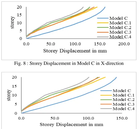
Fig. 8 : Storey Displacement in Model C in X-direction
Fig. 9 : Storey Displacement in Model C in Y-direction
From figure 8 and 9 , we can see that fluid viscous damper reduces the storey displacement by 27% for model C.4 and also, by 14% for model C.3 when compared with model C in X-direction. Also by 29% for model C.4 and by 17% for model C.3 in Y-direction.
Fig. 10 : Storey Displacement in Model D in X-direction
Fig. 11 : Storey Displacement in Model D in Y-direction
From figure 10 and 11 , we can see that fluid viscous damper reduces the storey displacement by 39% for model D.4 and also, by 40% for model D.3 when compared with
model D in X-direction. Also by 40% for model D.4 and by 51% for model D.3 in Y-direction.
6.2 Storey Drift :
Fig. 12 : Storey Drift in Model A in X-direction
Fig. 13 : Storey Drift in Model A in Y-direction
From figure 12 and 13, we can see that fluid viscous damper reduces the story drift by 78% for model A.4 and also by 65% for model A.3 when compared with model A in X-direction and in Y-direction.
Fig. 14 : Storey Drift in Model B in X-direction
Fig. 15 : Storey Drift in Model B in Y-direction
Fig. 16 : Storey Drift in Model C in X-direction
Fig. 17 : Storey Drift in Model C in Y-direction
From figure 16 and 17, we can see that fluid viscous damper reduces the storey drift by 75% for model C.4 and also, by 63% for model C.3 when compared with model C in X-direction. Also by 73% for model C.4 and by 64% for model C.3 in Y-direction.
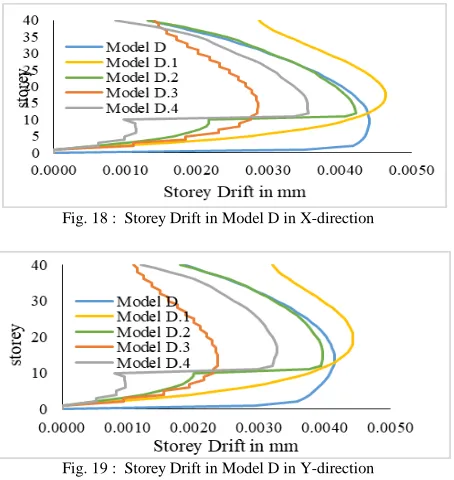
Fig. 18 : Storey Drift in Model D in X-direction
Fig. 19 : Storey Drift in Model D in Y-direction
From figure 18 and 19, we can see that fluid viscous damper reduces the storey drift by 18% for model D.4 and also, by 36% for model D.3 when compared with model D in X-direction. Also by 21% for model D.4 and by 43% for model D.3 in Y-direction.
6.3 Time Period :
Fig. 20 : Time Period in Model A
Fig. 21 : Time Period in Model B
From figure 20, we can see that FVD reduces time period by 41% for model A.3 and 40% for model A.4 when compared with model A. Figure 21, shows that FVD reduces time period by 40%for model B.3 when compared with model B.
Fig. 22 : Time Period in Model C
Fig. 23 : Time Period in Model D
7. Conclusion
Based on the results and discussion the following conclusions are made.
Up to 44% reduction in storey displacement was observed when FVD are provided till 10th floor in zigzag pattern while, reduction is up to 54% when FVD are provided in all external corner in zigzag pattern.
The storey drift decreased up to 78% when FVD are provided till 10th floor in zig-zag pattern. Also , It decreases up to 65% when FVD are provided in all external corner in zigzag pattern.
Around 40% reduction in time period was observed when FVD are used.
It is observed that, model B with aspect ratio 1 with dampers provided in zig-zag pattern in all external corners gives satisfactory result as compared with other models.
Model D with aspect ratio 1.5 with dampers provided in zig-zag pattern in all external corners also gives good result.
References
[1] Mohsen Kargahi and Chukwuma G. Ekwueme, “Optimization Of Viscous Damper Properties For Reduction Of Seismic Risk In Concrete Buildings ,” 13th World Conference on Earthquake Engineering Vancouver, B.C., Canada August 1-6, 2004
[2] Vajreshwari Umachagi, Katta Venkataramana, G.R.Reddy, Rajeev Verma,“Applications of Dampers For Vibration Control of Structures: an Overview” IJRET: International Journal of Research in Engineering and Technology, Nov-2013
[3] L. Mathew and C. Prabha, “Effect Of Fluid Viscous Dampers In Multi-Storeyed Buildings,” vol. 2, no. 9, pp. 55–60, 2014.
[4] Waseem Khan, Dr. Saleem Akhtar, Aslam Hussain, “Non-linear time history analysis of tall structure for seismic load using damper,” International Journal of Scientific and Research Publications, Volume 4, Issue 4, April 2014 [5] Su Myat Aye and Dr. Kyaw Moe Aung, “Comparative Study
on Seismic Response of RC Structures Using Viscous and Viscoelastic Dampers”, IJSETR, Vol. 3, Issue 8, 2014. [6] Naziya Ghanchi Shilpa Kewate , “Dynamic Analysis Of 25
Storey Rcc Building With And Without Viscous Dampers,” International Journal of Scientific & Engineering Research, Volume 6, Issue 12, December-2015
[7] Lavanya K R, Dr. K. Manjunatha, “Comparative Study On Seismic Effects Of Fluid Viscous And Viscoelastic Dampers In RCC Building,” International Research Journal of Engineering and Technology (IRJET) ,Volume: 03 Issue: 08 | Aug-2016
[8] P. Sajjan and P. Biradar, “Study On The Effect Of Viscous Damper For RCC Frame Structure,” pp. 31–36, 2016.
[9] M.L.V Prasad, Endow A Mazumder , “Use Of Viscous Damper As An Energy Dissipative Device In Steel Structures,” International Journal of Mechanical And Production Engineering, Volume- 4, Issue-6, Jun.-2016 [10] Ras, A.; Boukhari, B.; Boumechra N.; Hamdaoui, K.:
Dissipative capacity analysis of steel building using viscous bracing device. In:Fourth International Joint Conference on Advances in Engineering and Technology, AET, NCR, December 13–14, India (2013)
[11] Pouya Azarsa, Mahdi Hosseini, Seyed Amin Ahmadi, Prof. N.V. Ramana Rao, “Seismic Behavior of Steel Buildings using Viscous Fluid Dampers by Non Linear Time History Analysis ,” Volume-6, Issue-6, November-December 2016 International Journal of Engineering and Management Research
[12] P.A.VIKHE , U.R.KAWADE,” Seismic Response Control of High Rise Building by using Viscous Damper,” Vol-2 Issue-5 2016, IJARIIE-ISSN(O)-2395-4396
[13] Dipak Patel , Vishal B Patel, Anshu Arya, “Energy Dissipation System in Multistorey Building,” International Journal of Innovative Research in Science, Engineering and Technology Vol. 6, Issue 5, May 2017 [14] C. Rama Krishna Reddy, Vaishali G Ghorpade, H.
Sudarsana Rao , “Analysis & Design of a High Rise Unsymmetrical Building with Dampers,” International Journal of ChemTech Research ,Vol.10 No.15, pp 349-357,2017
[15]SaiChethan K., Srinivas K.S., Ranjitha K.P, Seismic performance evaluation of fluid viscous dampers. IJRET, Volume: 06 Issue: 06, June 2017.
[16] Prafful S M, Naveen Kumar S, “Seismic Evaluation Of Multi-Storied Rc Building With Fluid Viscous Damper Using Response Spectrum Analysis,” International Research Journal of Engineering and Technology (IRJET) ,Volume: 05 Issue: 05 | May-2018
[17] Abhishek Kumar Maurya, V.K. Singh, “Analysis Of Building Using Viscous Dampers In Seismic Zone-V ,” [18] Rakesh Patwa, Dr. Savita Maru , “Comparative Study of
Seismic Analysis of Dampers in Asymmetrical R.C. Frame Building,” International Journal for Research in Applied Science & Engineering Technology (IJRASET) Volume 6 Issue VIII, August 2018
[19] Mendu Sneha Chandrika, Dr. B. Shivakumara Swamy, “Effect Of Damper Locations On Behaviour Of Plan Irregular Steel Structure Subjected To Dynamic Loading,” International Research Journal of Engineering and Technology (IRJET), Volume: 05 Issue: 06 | June-2018 [20]Yogesha A V, Dr. Jagadish G. Kori, “Comparative analysis
of Symmetrical and Unsymmetrical building using different combination of dampers,” International Research Journal of Engineering and Technology (IRJET), Volume: 05 Issue: 07 | July-2018
I.S. Codes
[21] IS456 (2000) - “Plain and Reinforced Concrete – Code of Practice’.
[23] IS 875 Part 1 (2015) -“Code of Practice for Design Loads (Other than Earthquake) for buildings and Structures “, Part 1- Dead Loads
[24] IS 875 Part 2 (2015) -“Code of Practice for Design Loads (Other than Earthquake) for buildings and Structures “, Part 2– Imposed Loads.
Vibha V. More P.G Student of B. R. Harne College of Engineering and Technology, Mumbai University.
Dr. Vikram A. Patil Principal and Guide of B. R. Harne College of Engineering and Technology, Mumbai University completed his Ph.D in Structural Engineering from IIT-Roorkee.