R E S E A R C H
Open Access
Adaptive space-time-frequency-coded UWB
system for wireless body area network
Miftadi Sudjai
*, Le Chung Tran and Farzad Safaei
Abstract
Wireless body area networks (WBAN) emerge as one of the main research streams for future wireless communications. One of the candidates for the WBAN physical layer is multiband orthogonal frequency division multiplexing ultra-wideband (MB-OFDM UWB) technology. However, despite its high data rate feature, it performs poorly in the very dispersive WBAN channel. To improve its performance, this paper proposes two novel mechanisms. First, the
space-time-frequency coding (STFC) is introduced into MB-OFDM UWB system in order to enhance the diversity order, resulting in a substantial improvement in the average error performance compared to the conventional MB-OFDM UWB system. Nevertheless, the performance is very sensitive to the body orientation towards the transmitter due to the body shadowing effect. Secondly, to improve further the performance of the proposed STFC MB-OFDM UWB system in all body directions, we propose an adaptive scheme that changes the modulation, STFC coding rate, and constellation power. Simulations confirm that an additional improvement in the order of 1 to 3 dB is achieved by the adaptive system. This improvement practically means a possible 12.5% to 50% reduction of the power consumption, which may also result in smaller size of WBAN devices.
Keywords:Adaptive system; MB-OFDM UWB; Space-time-frequency codes; WBAN
1 Introduction
There have been active engagements in the wireless body area network (WBAN) research in recent years. One of the key factors for the emergence of WBANs is the development of advanced, tiny-sized, lightweight, and extremely low power implantable and wearable sen-sors [1]. In addition, body centric radio propagation meas-urement campaigns and WBAN channel modelling have been robustly fostering research activities on WBAN tech-nologies and standards. In particular, WBAN is capable of alleviating the hurdle and inflexibility of cable-connected devices for, e.g., real-time monitoring of health conditions, via various implantable and wearable wireless sensors.
WBAN itself is a network of sensors or communicat-ing devices placed in, on, or off the body to monitor physiological activities and motions and communicate the data between those devices and/or to external devices. Numerous research publications and proposals of WBAN have been put forward, e.g., [1] and [2]. In order to
harmonize the development of WBAN, IEEE set up a technical group TG6 within 802.15 to standardize the WBAN in November 2007. IEEE 802.15 TG6 released the WBAN standard in February 2012 that includes the impulse radio ultra wideband (IR-UWB) as its physical layer [3]. Prior to this standard, IEEE also released the WBAN channel models that defined four different chan-nel conditions, i.e., CM1 to CM4, in which CM4 models thebody-to-externallink [2].
Another competing technology for a short range, very high data-rate communication is multi band orthogonal frequency division multiplexing ultra-wideband (MB-OFDM UWB), endorsed by the WiMedia Alliance [4,5]. It combines the capability of OFDM to flatten the response of dispersive, frequency selective channels of UWB, while maintaining the benefit of high capacity of UWB. It is designed to operate at up to 1 Gbps, at low cost and with low power consumption.
Meanwhile, multiple-input multiple-output (MIMO) technology is proven to be able to significantly increase the wireless system capacity for the same total transmis-sion power [6]. Its fundamental mechanism lies on the use of space-time coding (STC) [6-9]. In STCs, signals are * Correspondence:[email protected]
School of Electrical, Computer, and Telecommunications Engineering (SECTE), University of Wollongong, Northfield Avenue, Wollongong, NSW 2522, Australia
coded both in spatial and temporal domains, for example, using the Alamouti code [9] or other similar codes [7-9]. Alamouti code is designed for frequency flat fading and is capable of providing full rate and full diversity for up to two Tx and two Rx antennas. As a result, it enhances the diversity order and improves the link quality and capacity.
However, its direct application for a very dispersive UWB WBAN channel may not be suitable. Therefore, in order to attain higher data rates and capitalize on the rich dispersion of UWB WBAN channels, further addition of the frequency domain processing in STC can be deployed. So, the process becomes space-time-frequency coding (STFC). Readers may refer to [10-17] for more details about STFCs and its comparison with STC. It is intuitive that a STFC MB-OFDM UWB system may provide better link performance and higher data rate and system capacity. Hence, in [18], we proposed the combin-ation of STFC and MB-OFDM UWB, referred to as the STFC MB-OFDM UWB, as an improved physical layer for WBAN.
Radio propagation in, on, and surrounding a human body is greatly affected by environment, posture, activ-ities, and human tissue [19-24]. Numerous measurement campaigns on body centric propagations have been con-ducted to characterize the body centric channel, includ-ing UWB channels in the frequency bands of 3.1 to 10.6 GHz. Takada et al. show that the body centric channel varies according to the type of antennas, the position and orientation of antennas with respect to the body, the posture and motion of the body, and the variation of the human body itself [19]. Wang et al. suggest that the body shadowing is a prominent factor in short-range body-centric communications [20]. The effect of loca-tions of on-body devices, body size as well as the move-ment of the body is investigated in [21-24]. Finally, the aforementioned IEEE 802.15 TG6 in [2] has summarized and proposed four channel models CM1 to CM4 for UWB WBAN channels, which comprise seven scenarios. CM1 considers implant-to-implant link for medical information and communication science (MICS). CM2 determines implant-to-body surface and implant-to-external links operating in the same frequency band as CM1. CM3 considers body-to-body link, while CM4 considersbody-to-external link. Both CM3 and CM4 are proposed to operate in UWBs. Due to our focus on the UWB WBAN system, we will only consider CM3 and CM4 in this paper.
It is important to highlight the main differences be-tween UWB channel models for wireless personal area networks (WPANs) [25,26] and the aforementioned UWB WBAN channel. The WPAN channel models are based on the Saleh-Valenzuela model and do not con-sider the effect of human body, while the UWB WBAN channel models do. It is clearly shown in [2] that due to
the shadowing effect of human body, the UWB WBAN channel produces a larger amplitude standard deviation σ and a much greater exponential decay factorΓ com-pared to the UWB WPAN channel. Moreover, Γ varies significantly for different body directions with respect to the transmitter in the case of CM4 over the UWB WBAN channel. To the best of our knowledge, the per-formance analysis of a STFC MB-OFDM UWB system implemented in the WBAN channels has not been deeply explored. Thus, in [18] as previously mentioned, we present the performance analysis of STFC MB-OFDM UWB in CM3 and CM4 WBAN channels using the Alamouti code. One important observation drawn from this work is that the average error performance differs significantly in different body directions, i.e., the direction of the receiver placed on the surface of the body with respect to (w.r.t) the transmitter. This is due to the effects of line-of-sight (LOS), partial LOS, and body sha-dowing. These facts lead to the idea of adding an adaptive scheme to WBAN systems, in order to further improve their performance in all body directions.
50% further reduction of the total transmitted power, compared to the non-adaptive system. In other words, the adaptive scheme can significantly reduce the power consumption and dimension of WBAN devices.
The paper is organized as follows. Section 2 reviews the UWB WBAN channel models. Section 3 analyzes the proposed system model, including the adaptive algo-rithm and its decoding complexity. Simulation results and analyses are presented in Section 4. Section 5 con-cludes the paper.
1.1 Review of IEEE UWB WBAN channel models
Yazdandoost and Sayrafian presented the final document of the IEEE 802.15 TG6 channel modelling subcommittee, providing channel models to be used in body area net-works [2]. The channel models are used as a common plat-form for evaluating the perplat-formance of the physical layer from various proposals and measurement campaigns.
The channel models are drawn from three possible types of nodes, namely implant nodes, body surface nodes, and external nodes. Implant nodes are implanted below the skin or inside the human body. Body surface nodes are placed on the surface of the human skin or at most 2 cm away, and external nodes are placed between a few centimeters and up to 5 m away from the body. Figure 1 shows the possible communication links be-tween the nodes and the defined channel models CM1 to CM4. CM1 defines an implant-to-implant link (scenario 1, denoteS1) operating in the MICS band (402 to 405 MHz). CM2 determines implant-to-body surface (S2) and implant-to-external (S3) links, operating in the same band as CM1. CM3 defines a body surface-to-body surface link for both LOS (S4) and non-line-of-sight (NLOS) (S5) scenarios. CM3 is intended to operate in seven different bands, including the UWB band (3.1 to 10.6 GHz). CM4 determines a body surface-to-external link for both LOS (S6) and NLOS (S7). It is applied to three different frequency bands, including the UWB band. In this work, we only consider CM3 and CM4 for the UWB band.
1.2 Review of CM3 channel model
The CM3 for the UWB band is derived from a measure-ment campaign in a hospital room environmeasure-ment. The channel response is characterized by a power delay pro-file (PDP) as follows [2]:
h tð Þ ¼X L−1
l¼0
alexpð Þjϕl δðt−tlÞ ð1Þ
10 log10j jal2¼ γ 0;l¼0 0þ10 log10ðexp ð Þ−tlΓ ÞþS l≠0
p tlð jtl−1Þ ¼λ expð−λðtl−tl−1ÞÞ
p Lð Þ ¼L
L
expð ÞL L!
whereαlis the path amplitude,tlis the path arrival time,
and∅lis the phase for thelth path with an uniform
dis-tribution over [0, 2π], respectively. L is the number of arrival paths with averageL.δ(t) is the Dirac function,Γ is an exponential decay with a Rician factor γ0, S is a
normally distributed random variable with zero-mean and standard deviation of σS, and λ is the path arrival
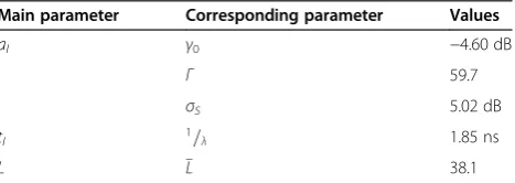
rate. The parameters of CM3 are presented in Table1.
1.3 Review of CM4 channel model
The CM4 model is based on office environment mea-surements in which the Tx antenna is fixed near to the wall, while the Rx antenna is placed at different positions on the human body. The effect of ground is considered in measurements. The channel response is characterized by the following PDP [2]
h tð Þ ¼X L−1
m¼0
αmδðt−τmÞ ð2Þ
where
αm
j j2¼Ω oe−
τm
Γ−k½1−δð Þmβ k¼ Δk ln10
10
; τo¼d=c; and βelognormal 0ð ;σÞ
αmis the amplitude of each path; τm,m = 1,…, L−1, is
the path arrival time;Lis the number of the arrival paths modelled as a Poisson random variable with the mean
Figure 1Communication links and channel models.
Table 1 Parameters of CM3 channel [2]
Main parameter Corresponding parameter Values
al γ0 −4.60 dB
Γ 59.7
σS 5.02 dB
tl 1=λ 1.85 ns
value of 400, Ω0 is the path loss; k is the K-factor
(NLOS),dis the Tx-Rx distance, and cis the velocity of light.
The parameters of CM4 also depend on the direction of body toward the Tx antenna and listed in Table 2.
From Table 2, the worst link is corresponding to the 270° body direction, rather than 180°, which may be rather counter-intuitive, and the channel behaviors of the 90° and 270° are significantly different. This might possibly be due to the different surrounding environments of the 90° and 270° directions during the measurement. This obser-vation will be reflected in our simulation results.
1.4 System model
1.4.1 STFC MB-OFDM UWB WBAN system with simple adaptive scheme
Figure 2 depicts our proposed STFC MIMO-OFDM UWB system withM-Tx antennas,N-Rx antennas, and a simple adaptive scheme. The data streamd(n)undergoes convolutional coding and interleaving, before being mapped to symbols. The body direction estimator mea-sures the orientation of the body w.r.t. the transmitter. The angular information is then fed back to the trans-mitter via a simple feedback loop in order to adjust its modulation, constellation power, and STFC coding rate accordingly. The adaptive modulation block selects either QPSK or BPSK, while the power control block adjusts the constellation power based on certain rules as detailed in the next section. For a fair comparison, those parameters are adaptively varied in a way that the average total power and total data rate over all four body directions are exactly the same as those in a non-adaptive system. The stream of modulated symbols is then converted by a serial-to-parallel (S/P) block into the symbol blocks (or vectors)
x¼½x1;x2;…;xNfft
T, where
Nfftis the fast Fourier trans-form (FFT)/inverse fast Fourier transtrans-form (IFFT) size.
The adaptive STFC block creates a space-time-frequency code with either a full rate or a 3/2-rate. For the full rate, it uses the Alamouti code [6] to convert the two consecutive symbol blocks, denoted as x1 and x2,
into a STFC block as follows:
X¼ xt;m
where x1 and x2 are symbol vectors transmitted from
the first and the second antenna at a given time slot, respectively. ( )*denotes complex conjugate. For 3/2-rate STFC, three symbol vectors are encoded following the Sezginer-Sari code [7]:
where a, b, c, and d are complex-valued parameters. Here, we use the optimal parameters a¼c¼pffiffiffi2 and b¼d¼1þjpffiffiffi7=4 as determined in [7].
We denote the matrix X in the general form as X¼
xt;m
TM, where the indextindicates the time slot and mindicates themth Tx antenna. Each of the symbol vec-tors in the matrixX is then converted into anNfft-point MB- OFDM symbol by the IFFT block, resulting in the STFC code matrixXOFDM whose elements are theNfft -point IFFT of the corresponding symbol vectors xt;m in
X. Hence, the transmitted matrix of STFC MB-OFDM symbols is:
The actual transmitted matrix is denoted as XZP whose elements are the Nfft-length vectors xOFDM;t;m in
XOFDM appended with the 37 samples zero-padded suffix (ZPS), denoted asxZP;t;m. ZPS is used here instead of cyclic prefix (CP) due to the fact that adding CP to an OFDM symbol will introduce redundancy into the transmitted signal. The CP produces correlation in the transmitted signal, which results in ripples in the average power spectral density (PSD) of MB-OFDM UWB system that could be as high as 1.5 dB [14]. This Table 2 Parameters of CM4 channel [2]
Body direction Γ(ns) k(Δk(dB)) σ(dB)
0° 44.6364 5.111 (22.2) 7.30
90° 54.2868 4.348 (18.8) 7.08
180° 53.4186 3.638 (15.8) 7.03
270° 83.9635 3.983 (17.3) 7.19
problem might force power back off at the MB-OFDM UWB transmitter, hence reducing the transmission range. When a ZPS is used, ripples in the PSD can be reduced significantly, thus the power back off problem at the transmitter can be mitigated and the system can achieve the maximum possible range. So, the transmitted signal becomes:
XZP¼ xZP;t;m
TM ð6Þ
The channels between M-Tx and N-Rx antennas are defined as the channel matrixH:
H¼
wherehm;n is the channel coefficient vector between the mth Tx antenna, for m = 1, 2,…, M, and the nth Rx antenna, n = 1, 2,…, N, containing L multipaths. The distribution and parameters of hm;n are determined by Equation1and Table1.
The received signal at the nth Rx antenna during the tth transmitted OFDM symbol duration is computed as:
rt;n¼ MB-OFDM symbol including ZPS transmitted from the mth Tx antenna, andnt;nis the zero mean additive white Gaussian noise (AWGN) vector. The ZPS is removed by an overlap-and-add-operation (OAAO) prior to the FFT operation. After performing OAAO, the received signal can be written as: where⊗denotes circular convolution. After the FFT block, the output signals of the STFC decoder are calcu-lated as:
where (•) denotes the Hardamard product between the vectors, rt;n¼FFT rOFDM;t;n
TN to be the matrix of the received signals after FFT, H ¼hm;nMN to be the channel response
matrix, and N ¼ nt;n
TN the matrix of noise. Then, we can rewrite (9) as:
R ¼X∘H þ N ð11Þ
where (°) denotes the operation which is similar to the normal matrix multiplication, except that each element in R is determined by (9). Thus, the detected vectors are decided by the following maximum likeli-hood (ML) rule:
Since the matrix X preserves its orthogonality in the similar manner as in a conventional STBC MIMO system, the STFC MB-OFDM UWB system can also employ a simple linear decoding process [14,15]. For simplicity, we can omit the time index t. Hence, in the 2I1O (2-input 1-output, i.e., by using two Tx antennas and one Rx antenna) configuration with M-PSK modula-tion, we have the following decoding metrics:
according to the standard [4]), and CND denotes the N
D
-dimensional complex space of the transmitted vector x . For the 2I2O (2-input 2-output, i.e., by using two Tx an-tennas and two Rx antenna) configuration, the decoding metrics are:
More importantly, each data point in an MB-OFDM symbol can be decoded separately rather than jointly [14], thus the decoding process is significantly simplified. In particular, the decoding metrics of each data at the kth subcarrier (k= 1,…, ND) in the MB-OFDM symbols
for the 2I1O configuration are:
Similarly, for the 2I2O configuration, the decoding
For the 3/2-rate STFC, we follow the decoding process mentioned in [7]. Generalization for the case of M-Tx and N-Rx antennas is straightforward.
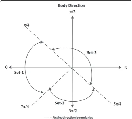
1.5 Adaptive selection algorithm
As mentioned previously, adaptive modulation and coding schemes have not been examined for WBANs using STFC MB-OFDM UWB technology, though they have been intensively researched for other sys-tems. This section proposes for the first time a simple-but-efficient adaptive modulation and space-time-frequency coding scheme for such a system. The adaptive scheme is controlled by the measurement of the angular direction of the body. Depending on which region among the three regions shown in Figure 3 the current body direction belongs to, the corre-sponding 2-bit angular information is fed back to the transmitter to select a suitable combination of its modulation, STFC coding rate, and constellation power. It is noted that the three regions in Figure 3 have been derived based on our observations that the
best channel behavior is corresponding to the 0° dir-ection, while the 90° and 180° directions possess relatively close error performances, and the worst channel behavior is the 270° direction.
Either QPSK or BPSK is used for modulation. We use two different STFC coding rates, namely coding rate 1 which uses the Alamouti full rate code, and coding rate 3/2 which uses the Sezginer-Sari 3/2 rate code. The normalized transmitted constellation power may take one of the three values 0.5, 1, and 1.5. The selection of the adaptive scheme is done in a way that the average data rate and total transmitted power over all main four directions of the body are main-tained exactly equal to those in a non-adaptive system (rate 1 STFC, constellation power 1, and QPSK modula-tion for all four direcmodula-tions) for a fair comparison. This is done as follows.
1. Data rate constraint: the lowest density signal constellation (BPSK) is used for the worst link (270°) in order to improve the system error performance over this direction. A higher density constellation (QPSK) is used for all other three directions. The highest rate STFC (rate 3/2) is selected for the best link (0°) while the rate 1 STFC is selected for all three remaining
directions. Thus, the average spectrum efficiency over the four main directions is maintained at 2 bits/s/Hz which is exactly the same as that in the non-adaptive system.
2. Power constraint: the normalized power of one is selected for the signal constellations (QPSK) for the 90° and 180° directions, similar to that in the non-adaptive system, while the highest power level (1.5) is selected for the best link (0°) to compensate for the possible performance degradation caused by the highest STFC coding rate (3/2) chosen for this direction. The above power allocation leaves the power of 0.5 for the BPSK signal constellation in the 270° direction. Thus, the total transmitted power over all four main directions is exactly the same as that in the non-adaptive system.
Tx 0.5. The proposed algorithm is summarized as follows:
1.6 Decoding complexity
Let P be the constellation size of the P-PSK modulator used in sets 1 and 2 (here, we used QPSK, soPis equal to 4). As a result, the constellation size of the BPSK modulator used in set 3 isP/2. The decoding process of set 1 with QPSK and 3/2 rate STFC is as follows: the decoder firstly has to determine x~3 from four possible
symbols in QPSK, prior to decoding ~x1 and ~x2 symbols.
Then, x~1 and ~x2 are decoded independently, given ~x3 is
known, for every QPSK constellation. Hence, the ML decoding complexity is the decoding complexity of ~x3,
which is in the order ofP, added with the complexity of two independent decoding processes of~x1andx~2given~x3
is known, which is equal to 2P. Thus, the overall decoding complexity is in the order of 3P, which is consistent with the analysis in [7]. Set 2 uses a QPSK modulator with the full rate Alamouti code as the STFC. The symbolsx~1 and ~
x2are decoded independently for every constellation,
lead-ing to a 2P-decoding complexity. Set 3 uses the full rate Alamouti code in which ~x1 and x~2 symbols are decoded
independently for every BPSK constellation point. There-fore, the ML decoding complexity in set 3 is 2P
2¼P:
There are four possible body directions with three pos-sible adaptive schemes. If the four body directions are
assumed to be equiprobable, i.e., the probability of each possible direction is 0.25, with the note that set 2 is used for two body directions, the overall complexity of the ML decoding process in the proposed adaptive scheme is 0.25(3P) + 0.5(2P) + 0.25(P) or 2P, beside the body dir-ection estimation. It can be inferred that the ML decod-ing complexity in our adaptive approach is in the order of P or O(P). It is obvious that the complexity of this adaptive system only linearly increases with respect to the number of signal constellations, thanks to relatively simple decoding processes.
For the body direction estimation, a simple direction sensor, e.g., by using a giant magneto resistance (GMR) thin film sensor chip [33], can be used. It is a robust magnetic sensor, which is capable to provide 360°-angu-lar measurements. The measured body direction is not fed back directly to the transmitter. Instead, depending on which region among the three pre-defined regions shown in Figure 3 this body direction belongs to, 2-bit angular information will be fed back to the transmitter to indicate this region in order for the transmitter to se-lect the corresponding combination of modulation, STFC structure, and constellation power. In other words, the proposed adaptive scheme could be implemented with only minor increase in system complexity.
1.7 Performance evaluations
The performance of a STFC MB-OFDM UWB system with and without the adaptive scheme will be examined in comparison with a conventional MB-OFDM UWB system in WBAN channel. The performance in terms of BER is assessed for three different configurations, i.e., single-input single-output (SISO), 2I1O, and 2I2O, assum-ing perfect channel state estimations be available at the re-ceiver. The total transmitted power from all Tx antennas is kept equal at all times in all configurations, in order to fairly compare their performances. Channel coefficients are assumed to be constant during two consecutive OFDM symbols, i.e., during each STFC block, but random between consecutive STFC blocks. Other simulation pa-rameters are listed in Table 3.
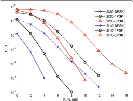
Figure 5 compares the performance of the proposed STFC MB-OFDM UWB WBAN system in CM3, using BPSK, QPSK, and 8PSK modulations, for both MIMO configurations. It clearly shows that the system can achieve a good BER performance from a reasonably low Eb/N0 range in both MIMO configurations, even if we use 8PSK modulation. For example, a BER of 10−4can be attained atEb/N0= 4.8 dB for 2I2O-QPSK, 8.5 dB for 2I2O-8PSK, 10.2 dB for 2I1O-QPSK, and 14 dB for 2I1O-8PSK. Beside the diversity order introduced by STFC, the reason for this good performance is that the length of zero-padded suffix NZPS = 37 is close enough to the mean number of multipaths in CM3, i.e., L¼38 (cf. Table 1). Therefore, the system experiences fre-quency flat fading channels. Significant improvement of at least 6 dB is shown in 2I2O, compared to 2I1O at BER = 10−4. In addition, the system performance im-proves by 2 to 4 dB, if we employ lower level M-PSK modulations. In particular, BPSK and QPSK modulations provide 6 and 4 dB better performances compared to 8PSK, respectively. As a result, BPSK and QPSK are of
particular interest and are used as the two main modula-tion constellamodula-tions in our proposed adaptive scheme.
The effect of body directions to the system perform-ance in the CM4 channel is depicted in Figure 6. In this simulation, we use the IEEE 802.15 TG6 WBAN channel model [2]. According to [2], which is based on an exten-sive measurement campaign in the office environment for medical applications, different orientation angles of the body cause different channel behaviors due to the possible change of propagation environment and the effect of body shadowing. This channel model reveals that the channel characteristics are worst in the 270° direction and that the channel parameters of the 90° and 270° angles are different. These facts might be because of the sur-rounding environments varied and/or the asymmetric ra-diation patterns of the antennas used in the campaign. Table 3 Simulation parameters
Parameters Value
FFT and IFFT sizeNfft 128
Number of ZPSNZPS 37
Convolutional coder (K= 7) rate One-half
Convolutional decoder and mode Viterbi, hard
Interleaver/de-interleaver Column-wise written, row-wise read
Average number of paths in CM3 38
Average number of paths in CM4 400
Body directions 0°, 90°, 180°, 270°
Figure 4Performance comparison between STFC MB-OFDM and conventional MB-OFDM in CM3 WBAN channel.
Figure 5Performance of STFC MB-OFDM in CM3 WBAN channel with various M-PSK modulations.
The performance comparison in Figure 6 reveals a sig-nificant degradation in the BER performance when the receiver (on the body) turns away from the transmitter. The front body (0° direction) has a LOS component, which results in the best performance compared to other directions. The back of the body (180° direction) suffers from a body shadowing effect, and the receiver only receives NLOS multipath signals. Nonetheless, the per-formance is still reasonably good, particularly with the 2I2O configuration, compared to the 270° direction. Its performance degrades 3.5 dB at BER = 10−3, compared to the front body. The 270° direction experiences the worst performance, and its performance is different from the performance of the 90° direction. This observation is consistent with the parameters of CM4 mentioned in Section 2.2. The average BER performance for each MIMO configuration shown by the dash-dotted curves in Figure 6 is calculated over four body directions. They are used as the benchmark for comparison with the adaptive system.
Figure 6 also shows the presence of error floors, where further increasingEb/N0 does not bring about a signifi-cant improvement. This is due to the fact that the ZPS is much shorter than the channel length in the very dis-persive CM4 channel. Thus, the inter-symbol interfer-ence (ISI) cannot be overcome completely. The residual ISI is still large enough to neutralize the performance. This is the reason why the MB-OFDM technique has been proposed where consecutive MB-OFDM symbols are transmitted over different radio frequencies (RF), thus avoiding the residual ISI. For simplicity, simulations are run here in the baseband rather than in the RF band, thus the error floors can be observed. In other words, the performance provided in the paper works as the lower bound for the improvement that could be pro-vided by the proposed system.
It is worth to note that while the particular level of performance improvement achieved by the proposed adaptive approach might vary should a different channel model be used, the overall idea of the proposed ap-proach (probably with slight modifications) could be still valid for other channel models.
To further improve the performance of the proposed STFC UWB WBANs, the proposed adaptive modulation and space-time-frequency coding scheme is implemen-ted. Figure 7 shows the improvement gained by the adaptive scheme, compared to the non-adaptive one, in both 2I1O and 2I2O configurations. The average BER of the adaptive scheme shown by a circled solid line is con-sistently better than that of the non-adaptive one by about 1 to 2 dB in a 2I1O configuration and about 1 to 3 dB in a 2I2O configuration in the medium-to-high SNR region. If we compare the average BER of the adap-tive scheme with the BER of the worst scenario (270° direction) in the non-adaptive one (cf. square-marked curves in Figure 6), the improvement is significantly higher, i.e., 5.5 dB at BER 5 × 10⁻²in the 2I1O configur-ation and 6 dB at BER 4 × 10⁻⁴in the 2I2O case. Compar-ing to the BER of the best link (0° direction, cross-marked curves in Figure 6) of the non-adaptive system in both MIMO configurations, as expected, the averaged BER of the adaptive scheme is slightly worse. This is because the adaptive system selects the highest STFC coding rate (3/2) for the 0° direction in order to maximize the capacity, with a price of minor performance degradation compared to the best performance scenario in the non-adaptive case.
It is noted that the aforementioned average BER improvements are achieved without any increase of the total transmitted power or any sacrifice of the data rate. In other words, an improvement in the order of 1 to 3 dB means a possible reduction of 12.5% to 50% of the total transmitted power, while maintaining the same
A
B
BER performance and data rate as in the non-adaptive STFC MB-OFDM UWB system. Due to the fact that power is the main constraint in WBAN applications [1], this power saving will significantly reduce the total power consumption of a WBAN system and/or reduces the dimension of WBAN devices.
2 Conclusions
This paper proposes a STFC MB-OFDM UWB system as an alternative high data-rate physical layer for a WBAN system. The results confirm that the proposed system can achieve significantly better BER perfor-mances, compared to the conventional MB-OFDM sys-tem. To improve the performance of STFC MB-OFDM UWB systems further, a simple body direction-based adaptive modulation and coding scheme is proposed. This adaptive scheme brings about an additional improve-ment in the order of 1 to 3 dB. Those improveimprove-ments prac-tically mean a possible 12.5% to 50% reduction of the total transmitted power, hence reducing the dimension of WBAN devices and prolonging their battery life. We con-clude that, with the price of slightly increased complexity, the proposed systems could be an effective solution to achieve a power saving and better average BER perform-ance for WBAN applications without sacrificing the data rate. Our future work will focus on the adaptive scheme driven by the measured signal quality in the receiver.
Competing interests
The authors declare that they have no competing interests.
Acknowledgements
The first author is grateful to the AusAID that provides financial support through the Australian Development Scholarship (ADS) scheme. The authors also would like to thank the anonymous reviewers for insightful feedbacks.
Received: 5 January 2014 Accepted: 24 December 2014
References
1. M Chen, S Gozalez, A Vasilakos, H Cao, VCM Leung, Body area networks: a survey. J. Mobile Netw. App.16(2), 171–193 (2010)
2. KY Yazdandoost, K Sayrafian-Pour,Channel model for body area network (BAN). IEEE 802.15 Working Group Document, IEEE P802.15-08-0780-12-0006, 2010
3. IEEE Computer Society,IEEE standard for local and metropolitan area networks-part 15.6: wireless body area networks(IEEE, New York, 2012) 4. WiMedia Alliance, Multiband OFDM physical layer specification.
(Final Deliverable 1.5, Aug 2009), http://www.wimedia.org/en/docs/ 10003r02WM_CRB-WiMedia_PHY_Spec_1.5.pdf. accessed 25 Sep 2011 5. WP Siriwongpairat, W Su, M Olfat, KJR Liu, Multiband-OFDM MIMO coding
framework for UWB communication systems. IEEE Trans. Signal Process. 54(1), 214–224 (2006)
6. SM Alamouti, A simple transmit diversity technique for wireless communications. IEEE J. Select. Areas Commun.16(8), 1451–1458 (1998) 7. S Sezginer, H Sari,A high-rate full-diversity 2 × 2 space-time code with simple
maximum likelihood decoding(Paper presented at the International Symposium on Signal Proceesing and Information Technology, IEEE, Giza, 2007), pp. 1132–1136
8. LC Tran, J Seberry, BJ Wysocki, TA Wysocki, T Xia, Y Zhao, Two new complex orthogonal space-time codes for 8 transmit antennas. IEE Electron. Lett. 40(1), 55–56 (2004)
9. LC Tran, A Mertins, TA Wysocki, Quasi-orthogonal space-time-frequency codes in MB-OFDM UWB. Elsevier J. Comput. Electric. Engin.
36(4), 766–774 (2010)
10. LC Tran, A Mertins, E Dutkiewicz, X Huang,Space-time-frequency codes in MB-OFDM UWB communications: advanced order-8 STFC and its performance(Paper presented at the International Symposium on Communication and Information Technology, IEEE, Sydney, 2007), pp. 380–385
11. AF Molisch, MZ Win, JH Winters, Space-time-frequency (STF) coding for MIMO-OFDM systems. IEEE Commun. Lett.6(9), 370–372 (2002) 12. M Fozunbal, SW McLaughlin, RW Schafer, On space-time frequency
coding over MIMO-OFDM systems. IEEE Trans. Wireless Commun. 4(1), 320–331 (2005)
13. LC Tran, TA Wysocki, A Mertins, J Seberry,Complex Orthogonal Space-Time Processing in Wireless Communications(Springer, New York, 2006) 14. LC Tran, A Mertins, Space-time-frequency code implementation in
MB-OFDM UWB communications: design criteria and performance. IEEE Trans. Wireless Commun.8(2), 701–713 (2009)
15. TH Tan, KC Lin,Performance of space-time block coded MB-OFDM UWB systems(Paper presented at the Annual Communication Networks and Services Research Conference, IEEE, Moncton, 2006), pp. 323–327
16. Q Yang, KS Kwak, Outage performance of STBC MB-OFDM UWB. AEU Int. J. Electron. Commun.63(8), 685–688 (2008)
17. LC Tran, A Mertins, E Dutkiewicz, X Huang,Unitary differential space-time-frequency codes for MB-OFDM UWB(Paper presented at the International Symposium on Communication and Information Technology, IEEE, Incheon, 2009), pp. 1161–1166
18. M Sudjai, LC Tran, F Safaei,Performance analysis of STFC MB-OFDM UWB in WBAN channels(Paper presented at the International Symposium on Personal, Indoor and Mobile Radio Communications, IEEE, Sydney, 2012), pp. 1704–1709
19. J Takada, T Aoyagi, K Takizawa, N Katayama, T Kobayashi, KY Yazdandoost, HB Li, R Kohno, Static propagation and channel models in body area. Euro-cost2100 TD(08), 639 (2008)
20. Y Wang, IB Bonev, JO Nielsen, IZ Kovacs, GF Pedersen, Characterization of the indoor multiantenna body-to-body radio channel. IEEE Trans. Antennas Propag.57(4), 972–979 (2009). doi:10.1109/TAP.2009.2014580
21. QH Abbasi, MM Khan, A Alomainy, Y Hao,Characterization and modelling of ultra wideband radio links for optimum performance of body area network in health care applications(Paper presented at the International Workshop on Antenna Technology, IEEE, Hong Kong, 2011), pp. 206–209
22. QH Abbasi, A Sani, A Alomainy, Y Hao, Experimental characterization and statistical analysis of the pseudo-dynamic ultra wideband on-body radio channel. IEEE Antennas Wireless Propag. Lett 10, 748–751 (2011)
23. QH Abbasi, MM Khan, A Alomainy, Y Hao,Radio channel characterization and OFDM-based ultra wideband system modelling for body-centric wireless networks(Paper presented at the International Conference on Body Sensor Networks, IEEE, Dallas, 2011), pp. 89–94
24. MM Khan, QH Abbasi, A Alomainy, Y Hao,Investigation of body shape variations effect on the ultra-wideband on-body radio propagation channel (Paper presented at the International Conference on Electromagnetic in Advance Applications, IEEE, Torino, 2011), pp. 1128–1131
25. J Foerster, Channel modeling sub-committee report final. IEEE 802.15 Work-ing Group document, IEEE P802.15-02/490r1-SG3a, Oct 2005
26. S Morosi, T Bianchi, F Gei, Frequency domain multiuser receivers for an IEEE 802.15.4a short range communication network. Trans. Emerg. Telecom. Tech 24(6), 545–551 (2013). doi:10.1002/ett.2597
27. A Czylwik,Adaptive OFDM for wideband radio channel, vol. 1 (Paper presented at the Global Telecommunication Conference, IEEE, London, 1996), pp. 713–718
28. T Keller, L Hanzo, Adaptive modulation techniques for duplex OFDM transmission. IEEE Trans. Vehicular Tech.49(5), 1893–1906 (2000) 29. T Keller, L Hanzo, Adaptive multicarrier modulation: a convenient
superframework for time-frequency processing in wireless communication. Proc. IEEE88(5), 611–640 (2000)
31. J Garzas, CB Calzon, AG Armada, An energy-efficient adaptive modulation suitable for wireless sensor networks with SER and throughput constraints. EURASIP J. Wireless Commun. Netw.2007, 1–7 (2007)
32. M Sudjai, LC Tran, F Safaei,A simple adaptive STFC MB-OFDM UWB system for WBAN applications(Paper presented at the International Symposium on Communication and Information Technology, IEEE, Surat Thani, 2013), pp. 60–65
33. CPO Treutler, Magnetic sensors for automotive applications. Elsevier J. Sens. Actuator A Phys91(1–2), 2–6 (2001). doi:10.1016/S0924-4247(01)00621-5
Submit your manuscript to a
journal and benefi t from:
7Convenient online submission 7Rigorous peer review
7Immediate publication on acceptance 7Open access: articles freely available online 7High visibility within the fi eld
7Retaining the copyright to your article