R E S E A R C H
Open Access
Theoretical analysis and compensation for the
joint effects of HPA nonlinearity and RF crosstalk
in VBLAST MIMO-OFDM systems over Rayleigh
fading channel
Maha Cherif Dakhli
*, Rafik Zayani, Oussama B Belkacem and Ridha Bouallegue
Abstract
In this paper, we investigate the joint effects of nonlinear distortions due to high-power amplifier (HPA) and radio-frequency (RF) crosstalk on the performance of a multiple-input multiple-output-orthogonal frequency division multiplexing (MIMO-OFDM) system. The performance of the vertical bell laboratories layered space-time (VBLAST) MIMO-OFDM system, in terms of bit error rate (BER) and system capacity, is derived and evaluated for a Rayleigh flat fading channel. In the performance analysis, M-ary quadrature amplitude modulation (M-QAM) is considered and the joint effects of nonlinear HPA distortions and RF crosstalk are studied. Theoretical results and comparisons are provided for several system parameters, such as the input back-off (IBO) and crosstalk intensity. It is shown that the results obtained from the theoretical study are very close to the ones obtained from the simulation. Indeed, we introduce a nonlinear distortion cancellation (NDC) technique to estimate and mitigate nonlinear distortions and crosstalk effects jointly.
Keywords:MIMO; OFDM; HPA; Crosstalk; Nonlinear distortion cancellation; MMSE
1. Introduction
The combination of multiple-input multiple-output (MIMO) and orthogonal frequency division multiplexing (OFDM) guarantees high performance with high data rates in 4G broadband wireless communications [1]. In-deed, OFDM combats frequency-selective fading effect-ively by dividing a wideband frequency-selective fading channel into parallel narrowband flat fading subchan-nels, while MIMO systems increase the data rate signifi-cantly over single-input single-output (SISO) systems by employing multiple transmit and receive antennas.
Like in classical SISO-OFDM, MIMO-OFDM exhibits large peak-to-average power ratios (PAPR), i.e., large fluc-tuations in their signal envelopes. Moreover, the perform-ance of the transceiver is very sensitive to nonlinear distortions caused by high-power amplifiers (HPAs). On the other hand, MIMO transceivers use multiple trans-mission/reception paths implemented in the same chipset.
Crosstalk or coupling effect is the result of the interfer-ence between the signals of different paths, and it affects the quality of the transmitted signal and degrades the sys-tem performance. This type of crosstalk can be linear or nonlinear as explained in [2], where the authors discussed the difference between linear MIMO crosstalk, which is relatively benign since it is being corrected by the MIMO equalizer, and nonlinear crosstalk that is generated before the HPA. This nonlinear crosstalk is not corrected by the MIMO receiver, and it is thus much more harmful. HPA nonlinearity in SISO-OFDM systems was investigated in [3], where the output at the HPA is expressed as the sum-mation of the input signal multiplied by a complex scale factor, and an additive Gaussian noise which is uncorre-lated with the input signal.
Recent research effort has dealt with the issue of HPA nonlinearity in MIMO systems. For instance, based on this study, the effect of HPA nonlinearity on the bit error rate of quadrature amplitude modulation (QAM) was analyzed in [4] for MIMO systems. In addition, the impact of HPA nonlinearity on the bit error rate was studied in [5] for
* Correspondence:[email protected]
Innov'COM Lab, Sup'Com, Carthage University, Ariana 2083, Tunisia
SDMA-OFDM systems and was analyzed in [3] in order to determine the parameters of amplification such as the complex attenuation coefficientK0and the variance of the
nonlinear distortion σ2d.
Up to now, in the open literature, these terms have been investigated analytically only for the soft envelope limiter (SEL) model [3], and a similar framework was proposed for the traveling wave tube amplifier (TWTA) and the solid-state power amplifier (SSPA) models, but limited actually to a semi-analytic study [3,5].
The compensation methods and comprehensive theor-etical analysis of several radio-frequency (RF) impair-ments together, in MIMO communication systems, are extremely challenging. A crossover digital predistorter was proposed for the compensation of HPA nonlinearity and crosstalk in MIMO systems and was evaluated through simulations [6,7].
In this paper, we investigate the joint effects of HPA nonlinearity and RF crosstalk in vertical bell laboratories layered space-time (VBLAST) MIMO-OFDM systems, and we derive the new closed-form probability density function (pdf ) signal-to-noise ratio (SNR) in different scenarios: (1) nonlinear MIMO-OFDM system and (2) nonlinear MIMO-OFDM system with crosstalk.
In addition, we introduce a new approach to derive analyticallyK0and σ2d, and this approach is valid for any
HPA model, such as TWTA, SSPA, and the real mea-sured one. Thus, a polynomial approximation is consid-ered in order to calculate the values of these parameters. Based on this approximation, we provide an analytical performance evaluation, in terms of bit error rate (BER) and channel capacity, of a VBLAST MIMO-OFDM sys-tem under a Rayleigh fading channel and memoryless nonlinear HPA model. Finally, we introduce a compen-sation method that aims to estimate and mitigate simul-taneously the HPA nonlinearity and RF crosstalk at the receiver side. This proposed method is based on the the-oretical analysis done in this paper.
Results were supported with MATLAB simulation of a VBLAST MIMO-OFDM system under a Rayleigh fading channel. The remainder of this paper is organized as fol-lows: In Section 2, the system model is introduced. The approximation of the HPA model is studied in Section 3. The performance of the VBLAST MIMO-OFDM system in terms of BER and capacity is evaluated in Section 4. Section 5 presents a nonlinear distortion cancellation (NDC) technique for compensating the nonlinear cross-talk. Numerical results and discussions are presented in Section 6, while the conclusion is given in Section 7.
2. System model
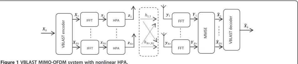
Let us consider the baseband equivalent VBLAST MIMO-OFDM system withNttransmit antennas andNrreceive
antennas shown in Figure 1. It is assumed that the system employsNcsubcarriers and M-QAM, and the fast Fourier transform (FFT) matrix is denoted byV∈ℂNc×Nc.
The frequency domain (FD) symbol Xkis assumed to
contain the source information, is mapped by using a VBLAST encoder, and is transmitted over a Rayleigh fading channel. The transmitted signalxk(n) from k
an-tenna at time instant n is obtained by means of an in-verse fast Fourier transform (IFFT) of the Xk(n) and is
given by
xkð Þ ¼n VHXkð Þn ð1Þ
2.1 Linear MIMO-OFDM system
Before reaching theNrreceiving antennas, the transmitted signals are affected by the propagation channel, which can be modeled by the propagation matrixHm,k. The received
signal, in a linear HPA case, is represented by
yLmð Þ ¼n
XNt
k¼1Hm;kð Þnxkð Þ þn nmð Þn ð2Þ where nm(n) is the additive white Gaussian noise
(AWGN) and Hm,k(n) is an Nc×Nc circulant time
do-main (TD) channel matrix at time instant n, which is formed by the channel response vector hm,k(n) for the
link between transmit antenna kand receive antenna m. The FD expression of the received signal is obtained by taking the FFT of Equation2giving
YLmð Þ ¼n V yLmð Þn ð3Þ
Let YL(n,i) =VyL(n,i) = [Y1(n,i),…,YNr(n,i)]T denote the
vector of received signals in the linear case for all an-tenna on subcarrier i. Then, the received signal vector for each subcarrier can be expressed as
YLð Þ ¼n;i Hð Þn;i Xð Þ þn;i Nð Þn;i ð4Þ
where X(n,i) = [X1(n,i),…, XNt(n,i)]T is the vector that
contains transmitted signals from each antenna and the Gaussian noise term Nð Þn;i as obtained by FFT of the thermal Gaussian noise of the receiver has zero mean and varianceσ2
n. The frequency domain channel transfer
matrixH(n,i) in Equation4is given by
on subcarrier i at time n between the kth transmit and
2.2 Nonlinear MIMO-OFDM system 2.2.1 Nonlinear HPA model
Memoryless power amplifiers are completely character-ized by their amplitude (AM/AM) and phase (AM/PM) conversions, which depend only on the current input signal value. Considering the complex envelope xk¼ρk ejθk of the HPA input at each branch whereρkandθk
de-note, respectively, the amplitude and the phase ofxk, the
complex envelope of a memoryless HPA output zk(n)
can be modeled as follows:
zkð Þ ¼n g½xkð Þn ¼A ρk ejðθkþPð Þρk Þ
¼S ρk ejθk ð6Þ
whereg[.] is the HPA transfer function andA(.) andP(.) denote the HPA AM/AM and AM/PM conversions, re-spectively. For a nonlinear HPA model, we consider Saleh's model [8], which has the advantage of good ac-curacy and reasonable complexity than other models. The AM/AM and AM/PM conversions can be repre-sented as follows [5,9]:
A ρk ¼ αaρk
1þβaρk2; P ρk ¼ αpρk2
1þβpρk2 ð7Þ
whereαaandβaare the parameters that decide the
non-linear level, andαp and βpare phase displacements. For
validation of our theoretical results, the operating point of the amplifier is usually identified by the‘back-off’. In the simulations, we define the input back-off as [9]
IBO¼10 log10 A 2 0
P0 ð8Þ
whereA0is the saturation amplitude at the input of HPA
and P0 is the input average power. From the Bussgang
theorem and by extending that to complex Gaussian processes, the output signal at the HPA can be expressed as [3]
zkð Þ ¼n K0xkð Þ þn dkð Þn ð9Þ
where K0is the attenuation coefficient and dk(n) is the
nonlinear distortion term uncorrelated with the input
signalxk(n). The value ofK0is given by Dardari et al. in
([3], eq. (19)) by
K0¼ 1
2E S′ ρk þ
S ρk ρk
ð10Þ
where S′(ρk) denotes the differential of S(ρk).
Further-more, the variance of the nonlinear distortion term (dk
(n)) is given by ([3], eq. (37))
σ2
d¼E jdkð Þn j2
¼E jzkð Þn j2
−j jK02E jxkð Þn j2
¼E S ρk 2
h i
−j jK02E ρk2
ð11Þ
The received signal at each antenna yNLm ð Þn is consti-tuted by the superposition of independently faded sig-nals, associated with the Nt antennas sharing the same space-frequency resource. The received signal is as-sumed to be corrupted by a Gaussian noise at the array elements, and it is given by
yNLm ð Þ ¼n
XNt
k¼1Hm;kð Þn ðK0xkð Þ þn dkð ÞnÞ
þnmð Þn ð12Þ
The frequency domain expression by taking the FFT of the received signal is given by
YNLm ð Þ ¼n V yNLm ð Þn ð13Þ
The received signal vector at each antenna on sub-carrier (i) can be written as [5,10]
YNlð Þ ¼n;i K0Hð Þn;i Xð Þ þn;i Hð Þn;i Dð Þn;i
þNð Þn;i ð14Þ
2.2.2 Nonlinear MIMO-OFDM with RF crosstalk
In MIMO transceivers, crosstalk or coupling effects are the result of the interference between the signals of differ-ent paths [6,11]. It is worth noting here that this crosstalk would be more significant in a highly integrated circuit (IC) design, mainly when the size of the prototype is small. This undesired MIMO crosstalk can occur in the radio channel, between the antennas, and also in the radio IC. In [12], crosstalk between the different RF transceiver
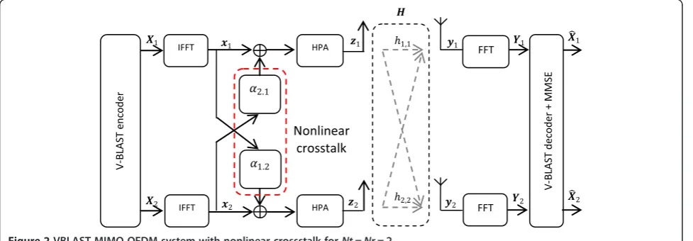
chains has been identified as a key issue when integrating a MIMO radio IC. This type of crosstalk can be linear and nonlinear as explained in [2], where the authors discussed the difference between linear MIMO crosstalk, which is relatively benign since it is being corrected by the MIMO equalizer, and nonlinear crosstalk that is not corrected by the MIMO receiver and is thus much more harmful. In this paper, we focus on nonlinear crosstalk that occurs at the radio IC level and introduced before nonlinear HPA (see Figure 2).
The HPA's output with the effect of crosstalk can be modeled as
zkð Þ ¼n g xkð Þ þn
XNt
l¼1;l≠kαlkð Þn⊗xlð Þn
h i
¼K0xkð Þ þn K0 XNt
l¼1;l≠kαlkð Þn ⊗xlð Þn
þdkð Þn ð15Þ
where g½ : is the HPA response for each branch,xl(n) is
the output of the FFT bloc of the l path of the trans-ceiver, and αlk(n) is the filter representing the crosstalk
and modeling the coupling between pathlto path k[7]. Since the signals in different paths use the same operat-ing frequency and have equal transmission power, cross-talk is more likely between the paths. In fact, the received signal of a nonlinear crosstalk is represented by
yNLmþcrossð Þ ¼n
XNt
k¼1Hm;kð Þn
K0xkð Þ þn K0
XNt
l¼1;l≠kαlkð Þn⊗xlð Þn
þdkð Þn
þnmð Þn
ð16Þ
In order to simplify the presentation of the theoretical study, we limit the calculation for two transmit antennas and two receive antennas, and we consider that the
coefficients of the crosstalk are equal (α21=α12=α) [6].
The frequency domain expression of the received signal vector for each subcarrier can be written as
YNLþcrossð Þ ¼n;i K0Hð Þn;iXð Þn;i þK0αHð Þχn;i ð Þn;i
þHð Þn;i Dð Þ þn;i Nð Þn;i ð17Þ
whereχð Þ ¼n;i x2ð Þn;i x1ð Þn;i
:
2.3 MMSE receiver
The transmitted signals by different antennas on subcarrier ican be estimated with the aid of a suitable linear combiner
W∈ ℂNr× Nt. The minimum mean square error (MMSE) detection minimizes the mean square error between the transmit signal and the estimated signal [13-15]. The optimal MMSE weight is obtained as follows:
WðMMSEÞ¼ HHð ÞHn;i ð Þ þn;i σ2nI
−1
HHð Þn;i
ð18Þ
where σ2
n is the noise variance andIis the matrix
iden-tity. After equalization, the approximated signal can be expressed as
^
Xð Þ ¼n;i WðMMSEÞYð Þn;i ð19Þ
3. Nonlinear distortion characterization
To evaluate the nonlinear distortion effects in MIMO-OFDM systems, in this section, we propose an analytical study to calculate the parameters of a power amplifier.
In [3,5,16], the terms of the nonlinear distortion are evaluated with semi-analytic expressions. Motivated by these results, we will expand this study in order to intro-duce a new approach to derivate analytically the com-plex attenuation coefficient K0 and the variance of the
nonlinear distortion σ2d, and this approach is valid for any HPA model even a real measured one. Thus, we will consider a polynomial approximation in order to calcu-late the values of these parameters.
3.1 Polynomial approximation of the nonlinear distortion As it is expressed by Equations 10 and 11, the analytical computation of K0 and the variance σ2d is not feasible
because we have to calculate the expectation (E[.]) of the complicated function. Therefore, we propose a new ap-proach, which is based on polynomial approximation in order to estimate the nonlinear HPA. In this case, the output of HPA can be represented by
z tð Þ ¼XL
the complex coefficients. Therefore, the new expression ofS(ρ) is given by:
In order to estimate the polynomial coefficient p2l + 1,
we use the least square (LS) approach [17]:
p ∧
k¼ XHkXk
−1
XHkzk ð24Þ
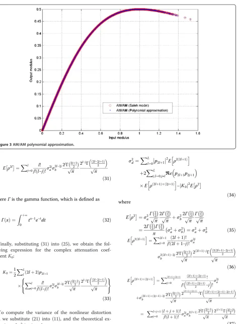
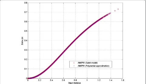
Figures 3 and 4 show the AM/AM and AM/PM ap-proximation, respectively, using a polynomial with order L= 10. The considered HPA is Saleh's model withαa= 1,
βa= 1, αp¼π3, and βp= 1 and input back-off (IBO) of
8 dB. We note from these results the AM/AM and AM/ PM characteristics given by Saleh's model and those ob-tained by polynomial approximation are well matched. 3.3 Analytical computation ofK0and σ2d
Using this polynomial approximation, the analytical ex-pression of K0 is obtained by substituting (22) and (23)
in (10) and we obtain
K0¼
This will be achieved by computing the 2l-order mo-ment (E[ρ2l]), whereρcan be written as
ρ¼a2þb21=2 ð26Þ
where a and b represent the real and imaginary parts, respectively. Then,
E ρ2l ¼Xlj¼0 l!
whereΓis the gamma function, which is defined as
Γð Þ ¼x
Z þ∞
0
tx−1e−tdt ð32Þ
Finally, substituting (31) into (25), we obtain the fol-lowing expression for the complex attenuation coef-ficientK0:
To compute the variance of the nonlinear distortion σ2
d, we substitute (21) into (11), and the theoretical ex-pression ofσ2dis given by
Substituting (35), (36), and (37) in (34), we can rewrite (34) as
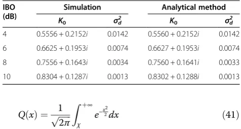
Table 1 presents the comparison of simulation and analytical results ofK0and σ2d obtained, respectively, by ((10) and (11)) and ((33) and (38)) for different values of IBO. According to this table, we observe a good agree-ment between simulation and theoretical results of the bothK0and σ2d, which validate our analysis.
4. VBLAST MIMO-OFDM performance analysis In this section, we evaluate analytically the performance of VBLAST MIMO-OFDM systems in terms of BER and the system capacity. The considered system uses M-QAM under a Rayleigh flat fading channel.
4.1 BER performance
A fading channel can be considered as an AWGN with a variable gain. The gain itself is considered as a random
variable with a given probability density function (pdf ). Moreover, the average BER can be calculated by aver-aging BER for instantaneous SNR over its distribution:
BER¼ Z þ∞
0
BERM‐QAMð Þγ pγð Þγ dγ ð39Þ
wherepγ(γ) is the pdf of the instantaneous SNR (γ). On the other hand, the bit error rate of a system, which implements M-QAM over a Rayleigh fading chan-nel, can be defined as [18]
BERM‐QAM¼
4 log2MQ
ffiffiffiffiffiffiffiffiffiffiffiffiffiffiffiffiffiffiffiffi 3γblog2M
M−1
r !
ð40Þ
where M denotes the modulation order and γb¼σ2x σ2 n whileQis the standardQ-function defined as [18]
Figure 4AM/PM polynomial approximation. σ2
d¼
XL l¼0p2lþ1
2 X2lþ1
j¼0
2lþ1 ð Þ!
j!ð2lþ1−jÞ!σ
2j aσ
2 2ðlþ1Þ−2j b
2jΓ 2jþ1 2
ffiffiffi
π
p 2
2lþ1
ð Þ−jΓ ð2 2ðlþ1Þ−2jþ1Þ
2
ffiffiffi
π
p 8
< :
9 = ;
þ2XLj;l¼
0;j≠lℜe p2lþ1p2jþ1
Xlþjþ1
j¼0
lþjþ1
ð Þ!
j!ðlþ1Þ! σ 2j aσ
2ðlþ1Þ
b
2jΓ2jþ21 ffiffiffi
π
p 2ðlþ1ÞΓ 2lþ23
ffiffiffi
π
p
( )
−j jK02 σ2aþσ
2
b
Q xð Þ ¼ 1ffiffiffiffiffiffi
In this investigation, we calculate, theoretically, the instantaneous SNR (γ) and its pdf (pγ(γ)) in different sce-narios such as linear OFDM, nonlinear MIMO-OFDM, and nonlinear MIMO-OFDM with crosstalk. This analysis will be used to calculate the average BER. 4.1.1 Linear MIMO-OFDM system
Assuming perfect channel equalization in the receiver, a soft estimate can be obtained by applying the MMSE equalizer that's given by
^
Xð Þ ¼n;i HHð ÞHn;i ð Þ þn;i σ2nI −1HHð Þn;i
½Hð Þn;i xð Þ þn;i Nð Þn;i ð42Þ
The instantaneous SNR in the linear case after equalization is exponentially distributed with a pdf given by
pγð Þ ¼γ 1 Ωe−
γ
Ω ð44Þ
whereΩ=E[|H(n,i)|2].
Then, by substituting (40) and (44) into (39), the aver-age BER of the M-QAM MIMO-OFDM system can be expressed as
As shown in [18,19],
BERL¼ ðM−1Þ
4.1.2 Nonlinear MIMO-OFDM system
The analysis presented in this section is based on the as-sumption that the distortion caused by the HPA can be modeled as additive Gaussian noise, whose variance de-pends on the input signal and the nonlinearity HPA characteristics. Applying the MMSE equalizer to the re-ceived signal YNL(n,i), the following estimate of the transmitted signal is obtained:
^ The instantaneous SNR at the receiver in the presence of HPA nonlinearity is
γNL¼
, and Equation 48 then becomes
and thepdfis given by
pγ
NLð Þ ¼γ pℵðgð Þγ Þg′ð Þγ ð50Þ
where g(γ) =ℵ and g(f(ℵ)) =ℵ. Moreover, the instan-taneous SNR in the nonlinear case can be expressed by
γ¼ γcgð Þγ gð Þγ σ2
dþσ2n
ð51Þ
From this equation, we can deriveg(γ) and then deter-mineg′(γ), which are given by (52) and (53), respectively:
gð Þ ¼γ γσ
Table 1 Comparison of analytical and simulation results ofK0andσ2dfor different values of IBO,L= 10, and
4 0.5556 + 0.2152i 0.0142 0.5560 + 0.2152i 0.0142
6 0.6625 + 0.1953i 0.0074 0.6627 + 0.1953i 0.0074
8 0.7556 + 0.1643i 0.0034 0.7560 + 0.1641i 0.0033
Substituting Equations 52 and 53 in Equation 44, we
Then, the average BER of the M-QAM nonlinear MIMO-OFDM system is given by
BERNL¼
4.1.3 Nonlinear MIMO-OFDM system with RF crosstalk The detected signal at the receiver level in the presence of HPA nonlinearity and crosstalk can be expressed as
^
Then, the instantaneous SNR of the received signal is defined as
Proceeding in the same way as in the previous case, we considerer that ℵ ¼jHð Þn;i j2;γc¼j jK02σ2x
The instantaneous SNR in the nonlinear with crosstalk can be expressed by
γ¼ γcgð Þγ
gð Þγ σ2
dþgð Þγ γeþσ2n
ð59Þ
Similar to the nonlinear case, we can deduceg(γ) and g′(γ):
and similar to the previous case, we can obtain a closed-form expression for thepdf pγNLþcross:
Therefore, the BER expression of the M-QAM nonlin-ear MIMO-OFDM system with crosstalk is given by
BERNLþcross¼
The integrals presented in Equations 55 and 63 are computed using MATLAB in order to determine the average BER, because the calculation of these integrals is intractable. An approximation for this integral is sug-gested in full perspective.
4.2 System capacity
It is theoretically known that the MIMO system can pro-vide a greater data rate than a conventional wireless sys-tem. Thereafter, we focus on the effects of nonlinear amplification due to HPA and nonlinear crosstalk on the system capacity in the MIMO-OFDM system in the presence of an MMSE receiver. The theory expression for system capacity is given by [5]
C¼ log2½1þγ ð64Þ
5. Compensation of the joint effects of HPA nonlinearity and crosstalk
In this section, we introduce an iterative estimation and cancellation technique of nonlinearly distorted signals re-ceived by the VBLAST MIMO-OFDM transmission sys-tem. Indeed, we also propose two compensation methods for two scenarios such as (1) the nonlinear distortion due to HPA without crosstalk and (2) the nonlinear distortion with crosstalk. Accordingly, in scenario 1, we attempt to estimate and mitigate the nonlinear distortion term in Equation 9, and in scenario 2, we try to eliminate jointly the nonlinear distortion due to HPA and the crosstalk between the different branches present in Equation 15. 5.1 NDC in nonlinear MIMO-OFDM system
The NDC technique requires knowledge of the HPA parameters. Indeed, the aim of this paper is to estimate and mitigate simultaneously HPA nonlinearity and RF crosstalk basing on the theoretical analysis done in this paper, where we used a polynomial approximation in order to estimate the nonlinear HPA (g[.]), which is described in Section 3.
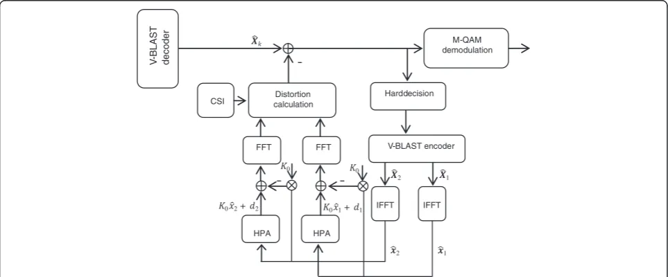
The proposed method is applied at the receiver side, independently for each antenna using its own HPA pa-rameters, and it consists of the following steps [5,20-22]:
Step 1: Using X^k, an estimaterk of the original
trans-mitted constellation Xk is obtained by applying hard
de-coding. This process is carried out for all active carriers. Using the recovered symbols, the time domain signal is reproduced via IFFT as
^
xkð Þ ¼n VHrkð Þn ð68Þ
Step 2: Using the nonlinear model of HPA that is approximated by a polynomial model, which is described
in the previous section, we compute the estimation dð Þkq
n
ð Þof the nonlinear distortion terms using Equation 9:
^
dð Þkqð Þ ¼n ^g ^x q ð Þ k ð Þn
h i
−K0 ^xð Þkqð Þn ð69Þ
where x^ð Þkqð Þn is the time domain representation of the recovered signal at iteration q and g^½ : is the estimated transfer function.
The frequency domain term is obtained by applying the FFT operator:
^
Dð Þkqð Þ ¼n V ^g x^ q ð Þ k ð Þn
h i
−K0x^ð Þkqð Þn
n o
ð70Þ Step 3: The distortion D^ð Þkq ð Þn is subtracted from the estimated signal ^xð Þkq . Using this result, the transmitted constellation is re-estimated in a new decoding/distor-tion cancelladecoding/distor-tion step, and the process can be carried out iteratively.
The technique is depicted in Figure 5.
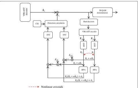
5.2 NDC in nonlinear MIMO-OFDM system with crosstalk We now present the proposed method in order to com-pensate the joint effects of the nonlinear distortion and crosstalk in the MIMO-OFDM system. Based on the scheme proposed in the previous subsection, we propose the compensation method for the two impairments together. This technique is provided in Figure 6.
Using the same steps above, we can determine the estimation of the nonlinear distortion term d^ð Þkqð Þ:n
M-QAM demodulation
Distortion calculation
HPA FFT
HPA FFT
CSI Hard decision
V
-B
LAS
T
de
code
r
V-BLAST encoder
1 2
1 2
0 1+ 1 0 2+ 2
0 0
IFFT IFFT
^
dð Þkqð Þ ¼n ^g x^ð Þkqð Þ þn XNt
l¼1;l≠kαlkð Þn⊗^x q ð Þ l ð Þn
h i
−
K0 ^xð Þkqð Þ þn
XNt
l¼1;l≠kαlkð Þn⊗^x q ð Þ l ð Þn
ð71Þ
The frequency domain term is obtained by applying the FFT operator:
^
Dð Þkqð Þ ¼n V ^g ^x q
ð Þ
k ð Þ þn
XNt
l¼1;l≠kαlkð Þn⊗x^ q
ð Þ
l ð Þn
h i
−
n
K0 ^xð Þkqð Þ þn
XNt
l¼1;l≠kαlkð Þn ⊗^x q ð Þ l ð Þn
o
ð72Þ
This process can also be performed iteratively. 6. Numerical results
In this section, we present theoretical and simulation results illustrating the performance of VBLAST MIMO-OFDM systems with the proposed compensation techniques for HPA nonlinearity and crosstalk, specifically on the average BER and system capacity with 64 subcarriers and 16-QAM. Herein, we consider a Rayleigh flat fading channel that is quasi-stationary on two successive OFDM symbols. The values of the parameters considered for HPA are assumed to be αa¼1; βa¼1; αp ¼π3; and βp ¼1.
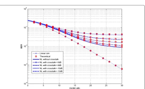
The average BER performances of the nonlinear OFDM system and the nonlinear MIMO-OFDM system with crosstalk are shown in Figures 7 and 8, respectively. In this plot, the first set of curves (solid lines) is obtained from simulation results of the system proposed, and the second set of curves (marker lines) is obtained from the theoretical study of the BER using (46), (55), and (63). It can be seen that the results obtained from closed-form expressions are very close to the ones given by the simulation.
Figure 7 illustrates BER versus Eb/N0 for IBO = {4-8}. As illustrated, Eb/N0 imposes a great impact on the BER performance. When IBO is decreasing (e.g., 4 dB), the modulated input signal can be higher thanA0with a
strong probability. This gives an irreducible error at higherEb/N0.
To further illustrate the effect of the crosstalk in the nonlinear MIMO-OFDM system, Figure 8 shows the average BER for different values of the crosstalk parame-ters, fixing IBO = 8 dB. The residual degradation on the performance of the average BER, due to the nonlinear crosstalk, increases as the parameters (α) become larger.
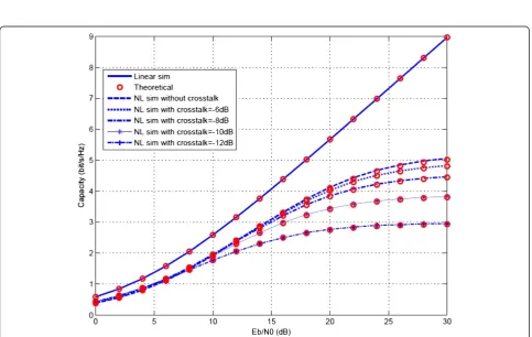
The system capacity (using Equations 65, 66, and 67) for the nonlinear MIMO-OFDM system and the nonlin-ear MIMO-OFDM system with crosstalk is plotted in Figures 9 and 10, respectively.
M-QAM demodulation
Distortion calculation
HPA FFT
HPA FFT
CSI
Hard decision
IFFT IFFT VBLAST encoder
VB
LAST
decoder
Nonlinear crosstalk
Figure 7Theoretical and simulation results for BER vs SNR for MIMO-OFDM systems.Polynomial approximation of HPA with 16-QAM,
Nc= 64,Nt=Nr= 2, and IBO = {4-8-10} dB.
Figure 8Theoretical and simulation results for BER vs SNR for MIMO-OFDM systems.Polynomial approximation of HPA with 16-QAM,
Figure 9Capacity evaluation in MIMO-OFDM system with linear and nonlinear HPA for different values of IBO.Nc= 64 andNt=Nr= 2.
Figure 11BER versusEb/N0 of MIMO-OFDM system with NDC technique forNc= 64,Nt=Nr= 2, and IBO = 8 dB.
Figure 9 show the effect of the nonlinearities due to HPA on the system capacity with different values of IBO. As noticed, the nonlinear distortion result causes a decrease in the capacity of MIMO-OFDM systems. On the other hand, the capacity of the system improves with the increase in the value of the IBO.
In Figure 10, we show the effect of the crosstalk on the system capacity as a function of Eb/N0, taking into account the HPA nonlinearity, for IBO = 8 dB. As observed, the system capacity increases as the crosstalk parameters (α) become larger. However, profiting of the RF crosstalk can improve the system capacity.
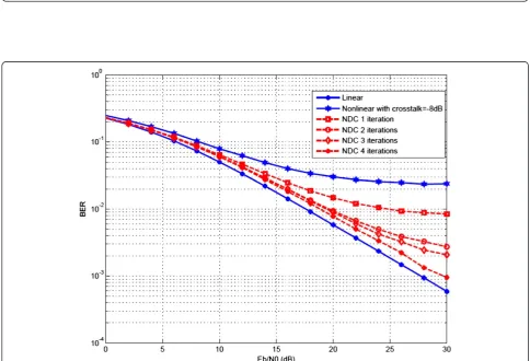
Finally, Figures 11 and 12 show that the nonlinear distor-tion and the nonlinear distordistor-tion with crosstalk in MIMO-OFDM systems can be effectively compensated using the NDC technique even after one iteration. Moreover, an increase in the number of iterations gives a significant improvement in the estimation procedure, although it slightly increases the complexity of implementation.
7. Conclusions
In this paper, we have investigated and analyzed the joint effects of nonlinear HPA and crosstalk on the perform-ance of the M-QAM VBLAST MIMO-OFDM system, in terms of BER and system capacity over a Rayleigh fading channel. In addition, new closed-form pdf signal-to-noise ratios are derived in order to develop theoretical expressions of the average BER in different scenarios: nonlinear OFDM system and nonlinear MIMO-OFDM system with crosstalk.
On the other hand, we have introduced a compensa-tion method (NDC) that aims to estimate and mitigate simultaneously the HPA nonlinearity and RF crosstalk at the receiver side. This proposed method is based on the theoretical analysis done in this work.
Numerical results showing the joint effects of HPA nonlinearity and crosstalk on the performances of MIMO-OFDM were evaluated and compared. In fact, the results obtained using the theoretical expressions of BER are very close to the simulation results, and it was shown that the NDC method can efficiently compensate these two impairments even after one iteration.
Competing interests
The authors declare that they have no competing interests.
Received: 29 June 2013 Accepted: 13 March 2014 Published: 22 April 2014
References
1. SA Haider, K Noori, System design and performance analysis of layered MIMO OFDM communication systems, inICACT 2009(Phoenix Park, 15–18 Feb 2009)
2. SA Bassam, M Helaoui, FM Ghannouchi, Crossover digital predistorter for the compensation of crosstalk and nonlinearity in MIMO transmitters. IEEE Trans. Microw. Theor. Tech.57(5), 1119–1128 (2009)
3. D Dardari, V Tralli, A Vacarri, A theoretical characterization of nonlinear distortion effects in OFDM systems. IEEE Trans. Comm.48(10), 1755–1764 (2000) 4. J Qi, S Aïssa, On the power amplifier nonlinearity in MIMO transmit
beamforming systems. IEEE Trans. Comm.60(3), 876–887 (2012)
5. F Gregorio, S Werner, TI Laakso, J Cousseau, Receiver cancellation technique for nonlinear power amplifier distortion in SDMA-OFDM systems. IEEE Trans. Veh. Tech.56(5), 2499–2516 (2007)
6. R Zayani, R Bouallegue, D Roviras, Crossover neural network predistorter for the compensation of crosstalk and nonlinearity in MIMO OFDM systems, in
PIMRC 2010(Istanbul, 26–30 Sept 2010)
7. F Gregorio, J Cousseau, S Werner, T Riihonen, R Wichman, Power amplifier linearization technique with IQ imbalance and crosstalk compensation for broadband MIMO-OFDM transmitters. Eurasip Journal on Advances in Signal Processing (2011). doi: 10.1186/1687-6180-2011-19
8. AAM Saleh, Frequency-independent and frequency-dependent nonlinear models of TWT amplifiers. IEEE Trans. Comm.29, 1715–1720 (1981) 9. R Zayani, R Bouallegue, D Roviras, Adaptative predistortions based on neural
networks associated with Levenberg-Marquardt algorithm for satellite down links. EURASIP JWCN (2008). doi:10.1155/2008/132729
10. FH Gregorio, S Werner, JE Cousseau, TI Laakso, Iterative channel estimation for multiuser OFDM systems in the presence of power amplifier nonlinearities, inPIMRC'06(, Helsinki, 11–14 Sept 2006), p. 11 11. H Bouhadda, R Zayani, R Bouallegue, D Roviras, Levenberg memory
crossover neural network predistorter for the compensation of memory crosstalk and HPA, in19th European Signal Processing Conference EUSIPCO
(Barcelona, 29 Aug–2 Sept 2011)
12. W-C Hua, P-T Lin, C-P Lin, C-Y Lin, H-L Chang, CW Liu, T-Y Yang, G-K Ma, Coupling effects of dual SiGe power amplifiers for 802.11n MIMO applications, inIEEE Radio Freq Integr Circuits Symp(San Francisco, 11–13 June 2006), p. 4 13. P-J Bouvet, V Le Nir, M H'elard, R Le Gouable, Spatial multiplexed coded
MC-CDMA with iterative receiver, inProceedings of the IEEE 15th International Symposium on Personal, Indoor, and Mobile Radio Communications
(Barcelona, 8 Sept 2004), pp. 5–8
14. P Liu, MQ Wu, CX Xu, F Zheng, Multi-user MIMO linear precoding schemes in OFDM systems, inIEEE 3rd ICCSIT(, Chengdu, 9–11 July 2010) 15. M Dakhli, R Zayani, R Bouallegue, Compensation for nonlinear distortion in
MIMO OFDM systems using MMSE receiver, inIEEE 15th International Conference on Communication Systems, ICCS(, Singapore, 21–23 Nov 2012) 16. A Conti, D Dardari, V Tralli, An analytical framework for CDMA systems with
a nonlinear amplifier and AWGN. IEEE Trans. Comm.50(7), 1110–1120 (2002) 17. R Raich, H Qian, GT Zhou, Orthogonal polynomials for power amplifier modeling
and predistorter design. IEEE Trans. Veh. Tech.53(5), 1468–1479 (2004) 18. V Meghdadi, BER calculation, inWireless Communications, ed. by A
Goldsmith, 2008
19. M Agrawal, Y Raut, BER analysis of MIMO OFDM system for AWGN & Rayleigh fading channel. Int J Comput Appl34, 9 (2011)
20. P Drotar, J Gazda, M Deumal, P Galajda, D Kocur, Receiver based compensation of nonlinear distortion in MIMO-OFDM, inIEEE IMWS
(Aveiro, 22–23 Feb 2010)
21. P Drotar, J Gazda, P Galajda, D Kocur, P Pavelka,Receiver technique for iterative estimation and cancellation of nonlinear distortion in MIMO SFBC-OFDM(IEEE Trans, Consumer Electronics, 2010)
22. M Dakhli, R Zayani, R Bouallegue, A theoretical characterization and compensation of nonlinear distortion effects and performance analysis using polynomial model in MIMO OFDM systems under Rayleigh fading channel, in18th IEEE Symposium on Computers and Communications, ISCC
(Split, 7–10 July 2013)
doi:10.1186/1687-1499-2014-61