R E S E A R C H
Open Access
Mirror-image-based disjoint multi-paths
routing algorithm for maximizing
communication efficiency
Duzhong Zhang
1,2, Quan Liu
1,2*, Lin Chen
3, Wenjun Xu
1,2and Kehao Wang
1,2Abstract
The growing demands of high-speed and stable next generation 5Gcellular networks become the main stream in these years. In order to overcome a bottleneck of high-speed communication which is caused by limited spectrum resources, cognitive radio (CR) network has been proposed as a promising technology in 5Gnetworks. However, in CR networks, primary user (PU) networks lead another novelNP-Hardrouting problem on continuous data transmission, especially for some low-latency scenario. To settle this problem, a newmirror-image-based disjoint multi-path routing algorithm(MIDMRA) is presented in this paper. Amirror imagealgorithm is employed in MIDMRA to simplify the routing challenge of CR network’s multi-channel environment, and anOptimal Path Selectionmechanism is equipped to evaluate relationship between CR nodes and PUs when paths are being selected. Through theoretical and simulation analyses, MIDMRA has better performances on continuous communication under PU interferences than other multi-path routing algorithms.
Keywords: 5G network, Cognitive radio networks, Multi-path routing, Maximizing communication efficiency
1 Introduction
By 2020, mobile wireless networks would cover around 90% of the world, and much more mobile data traffic may be consumed on video-based content transmission [1]. Hence, next generation (5G) cellular networks are expected to satisfy more requirements on wireless com-munication with high speed, real-time, continuity, and reliability [2].
In order to meet these high-end requirements, future 5G networks needs more available spectrum resources [3]. However, most spectrum bands have been authorized to different wireless network standards in the last two decades by governments. The improvement in spectrum utilization has become the key problem.
In this case, cognitive radio (CR) technology as a promising technology in 5G network development has been proposed [3, 4]. As most authorized networks are not
*Correspondence: [email protected]
1School of Information Engineering, Wuhan University of Technology, Wuhan, China
2Key Lab. of Fiber Optic Sensing Technology and Information Processing, Ministry of Education, Wuhan, China
Full list of author information is available at the end of the article
operating at full load, vacant spectrum “holes” are gen-erated [5, 6]. CR networks as unlicensed users (second users (SUs)) could intelligently percept spectrum holes and dynamically access in to transmit data without inter-ference on authorized networks which is called as primary users (PUs). So idle spectrum bands could be reused by CR networks [7, 8].
Whereas, a novelNP-Hardmulti-path routing problem in CR network has been proposed in [9, 10]. As shown in Fig. 1, solid lines represent active paths, and dashed lines indicate inactive paths. If two paths are selected to transmit data as Fig. 1a, the communication may be interrupted by PUs’ arrivals. Conversely, if the distances between selected paths are larger enough as in Fig. 1b, two paths of communication could not be interrupted by one PU simultaneously, so the selected paths in Fig. 1b could be defined as “disjoint” [11]. However, PUs have larger interference range and unpredictable movements, and dif-ferent decisions on path selection would have important impacts on CR networks’ communication, especially in some CR networks which have high requirements on latency and continuity.
(a)
(b)
Fig. 1Difference between close routes and non-close routes.aClose routes.bNon-close routes
Therefore, to solve this NP-Hard problem, some sub-optimal solutions have been proposed. Beltagy et al. [9] and Karmoose et al. [12] give out solutions by utilizing CR nodes’ location information, the distances between nodes are considered in paths routing, but the methods of choosing paths in these type solutions have their own limitation, especially in a small communication topology environment. Ju and Evans [13] present a space and spec-trum disjoint mechanism, in which spaces and specspec-trum channels are guaranteed disjoint when it selects paths, while this mechanism pays more attention on the dis-joint between paths than on PUs’ arrivals. And as the preliminary work of this paper, [11] offers a Multi-layer based Multi-path Routing Algorithm and redefines this NP-Hard problem intodisjoint multi-path routing prob-lem in CR networks. Whereas, this solution is only suitable for multiple interface CR devices, which could not settle the problem for single interface CR users.
Thus, we would like to provide a novel multi-path route algorithmmirror-image-based disjoint multi-path routing algorithm(MIDMRA) in this paper to answer the disjoint multi-path routing problem in CR networks under single interface CR devices environment. In MIDMRA, amirror imagealgorithm is proposed for generating a sequence of connected original network’s mirror graphs as candidate paths selection graph. Meanwhile, through an optimal path selectionmechanism, a single path could be picked in the new connected graph, so multiple disjoint paths which we want could be split from the single selected path. Via analysis and simulation, MIDMRA could complete disjoint paths selection and obtain maximum communica-tion efficiencyin CR networks. The major contributions of this paper could be summarized as follows:
• By utilizing a mirror image pattern, multiple disjoint paths selection in one graph problem has been simplified into a single path selection in multiple graphs. As far as we know, the proposed mirror image approach has never been used by other existing works.
• Through employing anoptimal path selection mechanism, the disjoint multi-path route has been extended to a single interface CR device environment. • The deployment ofcommunication efficiency gives
out a relatively precise evaluation on the relationship between paths under PUs’ interferences via CR nodes’ sensing information.
The rest of this paper is organized as follows: in Section 2, a comprehensive introduction of related works is presented, and in Section 3, we would introduce and analyzeMIDMRAalgorithm in detail. The performance of MIDMRA would be displayed in Section 4, and the conclusion would be presented in Section 5.
2 Related work
In this section, related works’ introduction would be held. These related works’ introduction are divided into five parts in this section according to their routing methods and implementation environments.
2.1 Geographic solution
exponential level time complexity for processing. Mean-while, worse results may be generated when the routing space is not large enough.
2.2 Spectrum disjoint solution
This type solution is presented in [13] by Ju Suyang and Evans Joseph B through using spectrum disjointness. A space discovery protocol is designed to find multiple space disjoint paths, and aspectrum discovery protocolis designed to guarantee spectrum bands which are used by nodes in selected paths that are independent to neighbor nodes. So, the chosen paths are space disjoint, edge dis-joint, and spectrum disjoint. This protocol could avoid an interference between neighbor nodes and guarantee the communication of nodes in disjoint paths that are spec-trum uncorrelated. However, this solution does not focus on the disjoint multi-path routing problem in CR net-works, and the spectrum bands of selected links may not be independent from each other, and PUs’ interference ranges are much larger than CR nodes, which leads to path selections that are useless.
2.3 Jammer similarity solution
Different from the solutions above,jammer disjoint rout-ing problemdoes not focus on CR networks, even multi-channel environment may not be included. But this prob-lem is similar to disjoint multi-path routing probprob-lem in CR networks, and related solutions could present many heuristic inspirations. A jammer is random in appear-ance and has large interference range leading to users’ communication interruption, which is similar to PU, so multi-path route in a jammer environment should also find disjoint paths to guarantee data transmission. In [14], the shortest multi-path routing and cooperative packet caching are used to decrease packet loss led by route faults. While Wu K. et al. proposed an IP-layer multi-path selection mechanism to select multiple “least connectiv-ity” paths by using IP-layer topological disjointness in [15]. And a time-dimension solution on multi-path route in jammer environment is presented in [16, 17]. By dividing long-term priori channel sensing information intontime slots, a greedy algorithm is utilized to choose paths which have least occupied time slots, then, jammers’ interference could be decreased to the bottom. However, this type solu-tions could not be shared in CR network environments since differences exist between jammer and PU (e.g., jam-mer is always chasing users’ wireless single for attacking, which increases predictability of jammer’s movements).
2.4 Sparse network solutions
Routing researches in sparse networks are different from the dense networks, which pay more attentions on delay and disruption tolerance [18]. But because the pursuing of continuous communication in sparse networks is similar
to the main idea of this paper, the solutions in sparse networks and solutions on disjoint multi-path routing problem in CR networks have possibilities to find a com-mon point. In [19], Zhao et al. give out a packet-level data replication algorithm to solve the delay tolerance problem under unstable sparse CR networks. While a multi-copy routing protocol (McRTP) is held to improve delivery rate and latency in [20]. By redefining contact time predic-tion model, McRTP could optimize path selecpredic-tion. And through a novel copy count assignment mechanism, net-work traffic load could be controlled.
2.5 Multi-layer based multi-path routing algorithm As we know, there is no unified standard on communi-cation technology in CR networks, single interface and multiple interface CR nodes exist in existing CR networks. However, communication patterns of these two types of CR nodes have huge differences, and their solutions on disjoint multi-path routing problem in CR networks should not be the same too.
Consequently, we have proposed multi-layer based multi-path routing algorithm (MMRA) [11]. For quan-tizing PUs’ appearances, a newspectrum history matrix (SHM) is proposed for calculating PUs’ movements in time and spectrum dimensions. And CR node distribu-tions are rearranged according to their SHMs by a multi-layer dividing algorithm. Then,path selectionmechanism collects paths in each layer and recombines them. Thus, selected multiple paths are the disjoint paths which could transmit data with maximum communication efficiency under PUs’ interferences. However, this multi-path rout-ing method is only suitable in multiple interface environ-ment since reselected CR nodes may exist in chosen paths. CR nodes with single interface could only be selected once, otherwise whole network’s communication would be restricted by this bottleneck. Hence, a novel solution on single interface CR nodes is needed.
3 Mirror-image-based disjoint multi-path routing
algorithm
As stated previously, our previous work [11] has been pro-posed for disjoint multi-path routing problem in CR net-works in multiple interfaces scenario. Then, we would like to introduce mirror-image-based disjoint multi-path rout-ing algorithm (MIDMRA) for the problem under srout-ingle interface environment in this section.
3.1 Problem definition
Because the concrete definition of disjoint multi-path routing problem in CR networks has been proposed in our preliminary work [11], the problem definition would be introduced simply in part.
employed in this paper [11]. In SHM, long-term sensing information is split into pieces according to time and spec-trum distributions. And each piece could be indicated as ‘spectrum time slot’:
st,n=
1, PU is arriving. 0, PU is absent.
Wherest,nrepresents PU’s arrival status atnthchannel and tthtime period. Then, in each spectrum time slot, PUs’ arrivals could be simplified as the “ON-OFF” mode. While forTchannels andNtime periods, the SHMMscould be
depicted as
In Eq. 1, the PUs’ arrivals pattern could be mapped by a matrix for CR nodes. Therefore, if nodeiand nodej’s st,ns are both 1, these two nodes have high probability to
be under the same PU’s interference range. On the other side, if nodei has 0 and node jhas 1 in st,n, i must be
independent withj.
Hence, for selecting disjoint paths, CR nodes in the same path should pay more attentions on maintaining consis-tency of SHMs. So logical bit level “OR” is utilized in Eq. 2.
Mpath(α)=M1∪M2∪M3∪ · · · ∪Mm. (2)
WhereMpath(α)represents amnode pathαth’s SHM.
Correspondingly, in order to ensure the difference between paths, logical bit level “AND” is equipped to calculate multiple paths’ SHM.
MX =Mpath(1)∩Mpath(2)∩Mpath(3)∩· · ·∩Mpath(X). (3)
In this case, ifXpaths haveMXwhich is equal to 0, these
paths could send data under PUs’ interferences without transmission interruption. And these paths also have high probability to be the disjoint paths.
Whereas, the discreteMX is not suitable for
calculat-ing and evaluatcalculat-ing, especially when MX is not all 0 and MX1 andMX2 should be compared. Thus, a novel
evalu-ation indicatorcommunication efficiencyis employed for estimating available spectrum time slot in SHM.
C(X)= T·N− ||MX||
T·N (4)
where||MX||represents the sum ofMX, so the remaining
amount inT·Nis the available spectrum, and communi-cation efficiency could be depicted out byC(X).
Therefore, if ||MX|| could be minimized,
communi-cation efficiency C(X) would be maximized. Then, the disjoint multi-path routing problem in CR networks could be simplified to a solvable pattern:
Problem 1Given a n nodes’ weighted CR network graph
G(V,E,S) with N communication channels in T period, V indicates node’s information, E indexes edge’s informa-tion, and S represents each node’s SHM knowledge. Select R paths in this network to solve the following problem for maximizing network’s communication efficiency.
Minimize ||MR|| =
Before the introduction of MIDMRA, a discussion on why the routing algorithm in [16, 17] could not be utilized in this paper should be held, since the SHM mechanism is inspired from [16, 17]:
• PUs’ movements. Although PU and jammer have a similarity on random appearances, the basic interference patterns of these two distractions are different. Jammer is chasing and interrupting the wireless communication of users’ networks, which is different from PUs’ completely random appearances. • Priori route knowledge. In [16, 17], a quality
comparison algorithm and Yen’s ranking algorithm [21] are utilized for path selection before multi-path routing, so exponential time complexity is
unavoidable. Besides, because multi-path route mechanism in [16, 17] pays more attention on selecting as many as possible paths which could meet target formulation, the most appropriate routes may be ignored.
Hence, the route mechanism in [16, 17] could not be suitable for the Problem 1.
On the other side, SHM is a weight evaluation mecha-nism of networks, but traditional weighted disjoint multi-path route algorithms (e.g., Suurballe Algorithm in [22], R. Bhandari Algorithm in [23]) are still not suitable on this paper. In traditional weighted disjoint multi-path route, ordinary addition and subtraction are utilized on weighted value calculation, which is not appropriate for SHM.
It is obvious that nodeihas multiple parent paths and son paths in a multiple node CR network. For the same parent path of nodei(suppose it is pathk), different son paths would lead different final paths’ SHM (suppose there are two pathsaandb). Then, it can be depicted as
Sk+a=Sk∪Sa, Sk+b=Sk∪Sb
Sk+a∩Sa=Sk+b∩Sb=Sk.
However, different son paths may change the same par-ent path’s weight, which is in conflict with the routing principle of traditional weighted disjoint multi-path route. Therefore, route mechanism in [16, 17] and tradi-tional multi-path route solutions are not suitable for Problem 1, a novel disjoint multi-path routing algo-rithm which could find multiple spectrum-independent paths for maximizing communication efficiency C is necessary.
3.3 MIDMRA
To settle this problem, mirror-image-based disjoint multi-path routing algorithm (MIDMRA) is provided.
3.3.1 Main idea
For the Problem 1, two main questions should be addressed:
1. Selecting multiple paths which are space disjoint. 2. Proposing a new algorithm to guarantee paths’
disjointness with PUs by employing the SHM mechanism.
Whereas, these two questions should be considered together in routing process since the special reason which is mentioned in Section 3.2. So, if these two questions could be separate, it would be easier to settle Problem 1 than before. Hence, the mirror image algorithm is intro-duced to address question (1).
In network’s communication process, information exchange is always duplex from source to destination or from destination to source. SupposeRpaths existing in a CR network, theseRpaths could be seen asR/2 paths transmitting data from source to destination and R/2 paths from destination to source, which is like a communi-cation loop withRoverlaps. Then, if the loop could be cut and expanded to a long line, theRpaths would be changed to a long single path. Correspondingly, if aRhead-to-head and tail-to-tailmirror graphssequence could be generated from original CR network graph, the multi-path routing problem could be simplified to a single path routing prob-lem in the mirror graphs sequence. Therefore, questions (1) and (2) could be changed to find one single disjoint path by employing SHM mechanism.
For easy understanding, a simple example would be stated.
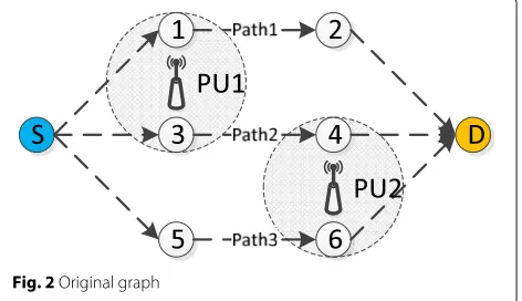
As shown in Fig. 2, a simple CR network graph is depicted. Eight nodes are equipped in this CR networks, dashed lines represent candidate links between CR nodes. Two PUs are appearing in one time period, suppose there are three spectrum channels,PU1 is occupying the first channel andPU2 is interfering the third channel. Nodes 1 and 3 are underPU1’s interference range, while nodes 4 and 6 are underPU2’s interference range. According to SHM mechanism, Path 1’s SHM could be calculated as Spath1= {1, 0, 0},Spath2andSpath3are{1, 0, 1}and{0, 0, 1},
respectively. So, if two paths are wanted, the best choice must be path 1 and path 3 since their communication efficiencyCis maximized to 1.
In this case, for selecting two disjoint paths, another mirror graph should be generated and connected to the original one. As shown in Fig. 3, the graph in which nodes are numbered with quotation marks is the mirror image of the CR network graph in Fig. 2. Hence, in this new graph, if a path could be selected fromStoSwithout recessive repeated nodes and get a maximumC as the blue path does in Fig. 3, the disjoint multi-path routing problem could be solved.
After the explanation above, main idea of MIDMRA has been shown out. To realize this idea, two concrete algo-rithms are proposed. The first is mirror image algorithm, which is responsible for constructing the sequence of con-nected mirror graphs. While the second isoptimal path selection mechanism, which is designed to route a single path from the new “source” to the new “destination” under the constraints of Problem 1 and nodes independence.
3.3.2 Mirror image algorithm
In this section, mirror image algorithm would be intro-duced in details.
Given the network-modeled weighted graph G =
(V,E,S)withV being the node set,E being the link set, andSbeing the node’s SHM set. If we want to findR dis-joint paths in this network, aMirrorimage()algorithm could be used as Algorithm 1.
Fig. 3MIDMRA
Algorithm 1Mirror image algorithm
Input: G(V,E,S), Source, Destination,R;
Output: G’(V’,E’,S’);
1: Copy G(V,E,S)R−1 times; 2: Number theRG(V,E,S); 3: fori=1 :R−1do 4: ifi==1then
5: connect destination ofG1to destination ofG2;
6: G= {G1,G2};
7: else
8: connect the relay junction of Gi to the
corre-sponding junction of Gi+1(relay junction is the
source or destination); 9: G= {G,Gi+1};
10: end if
11: end for
As shown in Algorithm 1, the detailed processes could be described as below:
1. At first, as a mirror image algorithm,R−1copies of original graphG should be generated
2. Number theR graphs. Original graph G is the first one, and the otherR−1graphs need to connect to G as a sequence. Hence, from the first to last graphs, they are numbered, while nodes are also numbered according to their own graph’s serial number; 3. Connect relay junctions between neighbor graphs in
head-to-head and tail-to-tail style (source connects with source, destination connects with destination).
And for the first and last graphs, only one relay junction is equipped.
4. AfterR−1iterations, a large mirror imageGcould be obtained.
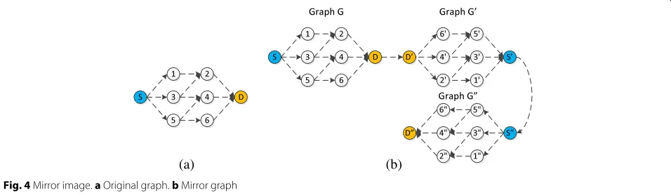
For better explanation, a simple example of three-path route which is using Algorithm 1 is presented.
As shown in Fig. 4a which is the original graph G, three paths are wanted from the source S to destina-tionD. By usingMirrorimage()algorithm, three mir-ror graphs are generated as G,G, andG, respectively, which is shown in Fig. 4b. They connect with each other through the dashed lines between relay junctions, desti-nationDis the relay junction between graphGand graph G, while source node S is the relay junction between graph G and G. Hence, if we could find an optimal path fromS toD, we could obtain three disjoint paths in the original graph. In Fig. 4b, the extended graph has 24 nodes which are numbered according to their graphs’ serial number, the number of node i is node i + 8 and i is node i+2 ∗8 actually for easy selection and calculation.
Consequently, a mirror image sequence environment has been established by mirror image algorithm. Whereas, how to find the appropriate optimal path is still a problem that should be solved.
3.3.3 Optimal path selection
For the purpose of single optimal path selection in the extend mirror image sequence, a novel single path rout-ing algorithm is necessary. As minimum S is needed
(a) (b)
in Problem 1, a Dijkstra-based optimal path selection mechanism is presented to solve this question.
Because the weighted distances calculation problem of Dijkstra algorithm which has been mentioned in Section 3.2, traditional Dijkstra based algorithm is not suitable for path selection in CR networks with SHM mechanism. Hence, to realize the novel Dijkstra-based optimal path selection algorithm, two questions is needed to be addressed.
• Through using the mirror image algorithm, relay junctions are connections between mirror graphs in the extended mirror image, which leads the same relay junctions which appeared in multiple candidate paths in mirror graphs. Hence, traditional distance calculation in Dijkstra algorithm could not be applied since one node’s distance could not be calculated twice. While SHMs are different, by using different parent paths or son paths, only one shortest path selection from the source to destination in a single graph does not fit the requirements of CR networks and could not find out the optimal solution. Therefore, a novel shortest weighted distance calculation method needs to be proposed.
• Mirror image algorithm increases CR nodes’ amount multiple times, but these additional nodes are virtual. Thus, a lot of the same nodes exist in different mirror graphs actually. Traditional Dijkstra algorithm could not be suitable for this situation. Then, how to avoid virtual node reselection in different graphs is also a problem.
To address these questions, a novel distance calculation approach is depicted as follows,
D(i,j) in the extended graph generated by Algorithm 1,Ris and Ris represent relay junctions between mirror graphs,nis the amount of nodes in a single mirror graphG, whileN andTare the total spectrum channels and time periods in SHM.
Therefore, in the routing process, four different types of distance calculation scenarios may exist:
• Whenj≤n, “path” fromi to j is in the first graph, so selected nodes in this long path are in one candidate path. Hence, logicalOR operation is taken for distance calculation according to the SHM mechanism.
• Whenn<j≤2n,j must be the node in the second mirror graph which is different fromi. In this case, the selected path which includesi and j should be two different paths actually. In order to calculate the SHM of the single long path through two mirror graphs, logicalAND operation is utilized. While,T·Nis also added in for mitigating calculation errors which are caused by multiple selected paths in mirror graphs. • Whenj>2n,j is in one of the multiple mirror
graphs. As a result, multiple different paths are selected in the mirror graphs fromi to j, and these paths in the middle section graphs should be from relay junctions to relay junctions. For mitigating calculation errors,j−n·T·Nis included.j−nis
round operation ofj−n, andis a minimum number which is used for preventingj that is divisible by n. • Whenj or j−n or · · · or j− extended graphs of nodes in a path. In this case, an∞ distance is appropriate for this new path.
As a result, the two questions are solved through Eq. 5. Then,the Dijkstra-basedPathselection()algorithm is proposed as Algorithm 2.
As shown in Algorithm 2, a detailed description could be concluded as follows:
1. At first, PATH list and DISTANCE list are prepared for storing the chosen paths and their distances, and source nodeS is put into PATH as the first path while 0 is its distance.
2. Search out the shortest path’s tail nodei ’s neighbor nodes and calculate distance fromS to node i ’s neighbor nodes.
3. Not all neighbor nodes could be added into PATH, the nodes who get∞distances must be deleted since they are reselected.
4. If the selected neighbor nodes are found in PATH, another path which is fromS to neighbor has been selected before. In this case, a comparison needs to be applied for finding the shorter path between these conflicting paths. After a series of comparison, the poor one would be deleted and the good one would be retained.
Algorithm 2Optimal path selection algorithm
Input: G(V,E,S), source, destination;
Output: PATH;
1: Create list PATH to save paths which have been selected, and list DISTANCE to save corresponding calculated distances;
2: Put source nodeSinto PATH as the first shortest path and put 0 into the corresponding DISTANCE;
3: whileDestination∈/PATHdo
4: Search the neighbor nodes of shortest path’s tail nodei;
5: Calculated distance D{S,is neighbors} between sourceSand tail’s neighbor nodes;
6: Delete nodes which cause∞distances; 7: for{i=1;i≤neighbor amount;i+ +}do 8: ifNeighbor∈PATHthen
9: Compare the conflicting paths SHM
SPath(S→neighbor)andSPath(confliction); 10: ifthey are the samethen
11: compare number of nodes in these two paths, and delete the longer one, if they are also the same, delete neighbor;
12: else if SPath(S→neighbor) ∩SPath(confliction) ==
SPath(S→neighbor)then
13: Delete corresponding path in PATH;
14: else if SPath(S→neighbor) ∩SPath(confliction) ==
SPath(confliction)then 15: Delete neighbor;
16: else
17: Remain neighbor node;
18: end if
19: end if
20: end for
21: Add remaining neighbor nodes to original shortest path and generate new paths;
22: Put new paths into PATH and put corresponding distance into DISTANCE;
23: Delete original shortest path in PATH;
24: Compare DISTANCE to find out the smallest one and define it as the new shortest path;
25: end while
26: The path from source to final destination in PATH is the optimal solution, split it into multiple pieces;
6. Compare distances in DISTANCE list, in order to find out the shortest path at present.
7. The last step is to repeat step (2) to step (6) until the destination has been found. The shortest path from S to destination is figured out. Split the path into multiple paths, they are the disjoint paths, and the algorithm is ended.
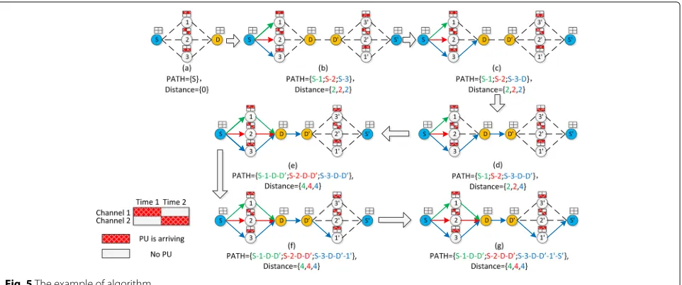
For easy understanding, a simple example of this algo-rithm is applied in Fig. 5. Two paths are wanted in a five-node CR network, and there are two candidate spec-trum channels which are sensed in two time slots, the detailed SHM is stated above each node. Red block in SHM represents spectrum time slot which is occupied by PUs, and white block indicates that there is no PU. The different colors of solid lines represent multiple paths which have been selected, and their distances and path lists are also stated in different colors. The shortest path fromStoSis found in PATH list asS−3−D−D−1−S which has the least distance by using Algorithm 2. Ulti-mately, a pair of disjoint paths are found asS−3−Dand S−1−D, their multi-path SHM is 0 andCis 1, which meets the requirement of Problem 1.
3.4 Optimization ability
After demonstrating how MIDMRA work, we now pro-vide analysis on the optimization and time complexity of this algorithm.
Theorem 1Given a weighted graph G(V,E,S), find
multiple paths by using MIDMRA, whose set is R, the com-munication efficiency C of these selected paths converge to the maximum.
Proof As it is hard to prove that selected paths has maximizedCdirectly, we would like to prove it by contra-diction. Suppose there is a pathkfromStoDin the long mirror graph, which has higherCthan MIDMRA selected patha, then, there must exist
C(path k)
=
T·N−Spath(k)S→R1∩Spath(k)R1→R2∩ · · · ∩Spath(k)R [D−n]→D
T·N >
C(path a)
=
T·N−Spath(a)S→R1∩Spath(a)R1→R2∩ · · · ∩Spath(a)R [D−n]→D
T·N ⇒D(path k) <D(path a).
Therefore, if the hypothesis of existing pathkhas higher C is valid, the distance D(path k) must be lower than D(path a), and pathacould not be chosen as the selected path according toPathselection()algorithm. Hence, the hypothesis is invalid.
Fig. 5The example of algorithm
1. If the path causes∞distance, it would be deleted. In this case, reselected nodes must exist in this path, which is in conflict with the rule of disjoint paths route under single interface terminal environment, so this assumption is incorrect.
2. When new paths are generated, the parent path would be deleted. According to the principle of MIDMRA, parent paths should be included in new paths when it is deleted, unless all neighbor nodes of parent paths are not appropriate for selecting or there are no neighbor nodes. The prior scenario breaks other deleting rules, and the last one means that the path could not route to destination, both assumptions are unable to find out disjoint paths. 3. It is complicated in this case as there are a lot of
comparisons between existing paths and a new path. Suppose there is tail nodei in new path k, which is a reselected node between pathk and another existing pathb in PATH. Then, path b should be compared with pathk from S to i.
If the hypothesis is correct, pathk must be deleted. Hence,SPath(k)S→imust be worse thanSPath(b)S→i.
So, there exist:
D(path(k)) <D(path(a)) and
D((path(b)S→i)+(path(k)i→D))≤D(path(k)). Therefore, the distance of pathb from S to i plus i toD must be lower than path k, while the distance of patha is higher than path k. Then, a new inequation could be depicted out,
D((path(b)S→i)+(path(k)i→D)) <D(path(a)). As a result, the new pathc which is the combination between pathb and path k could route to
destination and is better than selected patha, but
which is conflict with the assumption we have provided above.
Hence, the hypothesis of existing another pathkwhich is better than pathaselected by MIDMRA is invalid. In conclusion, multiple paths setRselected by MIDMRA has maximumC which could also be easily derived by this proof, The proof is completed.
3.5 Time complexity
On the other side, time complexity as an important ele-ment of algorithm should be analyzed. Since “WHILE” iteration is utilized in MIDMRA without distinct end point, the iteration times may not be a fixed value. Hence, we would prove that the time complexity of MIDMRA is polynomial in this part.
Theorem 2Suppose there exist n nodes in graph
G(V,E,S), to find r paths by using MIDMRA to maxi-mize their communication efficiency C, the time complexity would be polynomial.
ProofAs shown in Algorithm 3, MIDMRA could be divided into two parts, the first one isMirrorimage() algorithm, whose time complexity could be calculated out asT(Mirrorimage()) = O(r). While because the amount of pathsr is a constant value,T(Mirrorimage()) should beO(1).
Algorithm 3MIDMRA algorithm
Proof Input:G(V,E,S), Source, Destination, r;
Output:PATH;
1: Mirrorimage();
For another, the second part Pathselection()’s time complexity is hard to be figured out since there is a ’WHILE’ iteration, for easy calculation, Algorithm 2 is simplified as Algorithm 4.
Algorithm 4Simplified pathselection algorithm
1: whileDestination∈PATHdo
2: fori=1:r*ndo
3: Calculate distances between nodes and shortest path’s tail;
4: forj=1:the amount of neighbor nodesdo 5: Comparisons and deletions;
6: end for
7: end for
8: fori=1:the amount of PATHdo 9: Choose the shortest path;
10: end for
11: end while
In Algorithm 4, the main iteration could be separated into four parts: Destination finding iteration, distances calculation, neighbor nodes comparisons, and shortest path selection. Hence, these four parts could be indicated asTwhile,Td,Tcompare, andTshort. And time complexity of
Pathselection()could be calculated as Eq. 6.
TPathselection=Twhile(Td∗Tcompare+Tshort) (6)
Becauser∗nnodes exist in an extended mirror image, and all nodes are utilized in distance calculation, each iter-ationTd could be figured out asO(r∗n). While asris
constant,Td=O(n).
Because paths should be selected disjoint with each other, there only existr∗npaths in PATH list at most. For a single nodei,r∗nwould be the most comparison times. So,Tcompare≤O(r∗n)=O(n). Correspondingly, as there
arer∗npaths in PATH at most,Tshort ≤O(n). And the r∗npaths must have destinationD,Twhile≤O(n).
Consequently, the time complexity ofPathselection() algorithm could become as follows:
TPathselection=Twhile(Td∗Tcompare+Tshort)≤ O(n)(O(n)∗O(n)+O(n))=
O(n3+n2)=O(n3)
so, theTPathselectionis less thanO(n3), and the time
com-plexity of MIDMRA would become less thanO(n3+1)= O(n3). Time complexity of MIDMRA is polynomial. The proof is completed.
4 Evaluation performance
After a series of introductions and analyses, the details and advantages of MIDMRA algorithm has been presented. Then, simulations to evaluate performances of MIDMRA are stated in this section.
4.1 Simulation setup
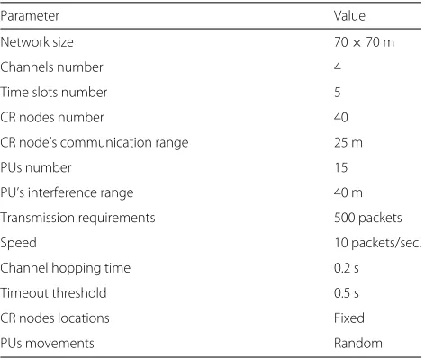
We generate a 70 to 70 m square space, and all CR nodes and PUs could only move in this plane space. In these simulations, CR nodes could not move, but PUs have random appearance and spectrum channel occupation capabilities. For accuracy of evaluation, simulation in each scenario would be repeated 100 times with random redis-tribution of CR node locations in each time. Some default sets of simulation parameter are stated in Table 1.
4.2 Communication efficiency
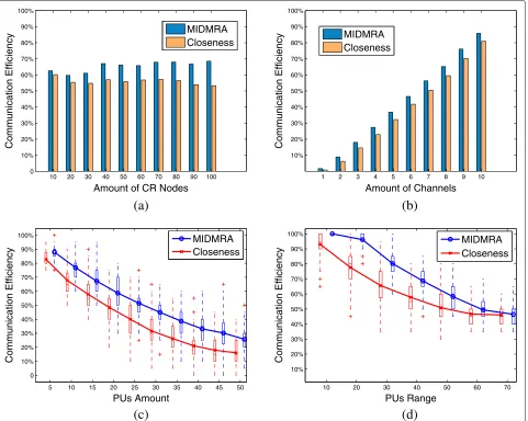
In order to evaluate MIDMRA, communication effi-ciency simulation analysis is utilized. As introduced pre-viously, there are few related works on this problem, especially without priori route information. Thus, the dis-joint routing mechanism in [9] is selected to compare with MIDMRA, which is represented by theCloseness mechanism in this paper. Because the closeness mecha-nism needs priori routing information, an all-path routing algorithm is added before comparison, which costs a lot of time and lengthens simulation period enormously.
For comprehensive comparison, this simulation is held in four different scenarios, and the result is depicted in Fig. 6.
4.2.1 Nodes’ variation
Under different CR node amounts, Fig. 6a figures out the comparison between MIDMRA and closeness.
Blue bars represent MIDMRA’s average communica-tion efficiencies of 100 iteracommunica-tions which result in different node amounts, and orange bars indicate average com-munication efficiencies of closeness. As the density of nodes increasing, MIDMRA maintains steady at a high-level communication efficiency, while closeness shows
Table 1Simulation parameters
Parameter Value
Network size 70×70 m
Channels number 4
Time slots number 5
CR nodes number 40
CR node’s communication range 25 m
PUs number 15
PU’s interference range 40 m
Transmission requirements 500 packets
Speed 10 packets/sec.
Channel hopping time 0.2 s
Timeout threshold 0.5 s
CR nodes locations Fixed
10 20 30 40 50 60 70 80 90 100 0
10% 20% 30% 40% 50% 60% 70% 80% 90% 100%
Communication Efficiency
Amount of CR Nodes
MIDMRA Closeness
1 2 3 4 5 6 7 8 9 10
10% 20% 30% 40% 50% 60% 70% 80% 90% 100%
Communication Efficiency
Amount of Channels MIDMRA
Closeness
5 10 15 20 25 30 35 40 45 50
0 10% 20% 30% 40% 50% 60% 70% 80% 90% 100%
PUs Amount
Communication Efficiency
MIDMRA Closeness
10 20 30 40 50 60 70
10% 20% 30% 40% 50% 60% 70% 80% 90% 100%
PUs Range
Communication Efficiency
MIDMRA Closeness
(a)
(b)
(c)
(d)
Fig. 6Communication efficiency comparison.aVariation with CR nodes.bVariation with channels.cVariation with PUs amounts.dVariation with PUs ranges
a decreasing trend since it is hard to find appropriate paths under a crowded node scenario. When the node amount has exceeded a fixed threshold, MIDMRA are all greater than closeness by 15 to 20%, which indicates that MIDMRA has better performance in different node amounts.
4.2.2 Channel variation
Figure 6b depicts communication efficiency compari-son when the amounts of channels are different. Blue and orange bars represent average communication effi-ciencies generated by MIDMRA and closeness, respec-tively. As the channels’ amount is increasing, the com-munication efficiency of these two mechanisms are growing steadily, and MIDMRA is always better than closeness.
4.2.3 PUs’ amount
In Fig. 6c, box plot is employed for comparison between MIDMRA and closeness when PUs’ amounts increase. Blue boxes and curves represent MIDMRA and red indi-cates closeness. Because the high density of PUs has important impacts on path selection in CR networks, the main trends of these two mechanisms is downward. How-ever, the communication efficiencies of MIDMRA are almost 10% higher than closeness at least no matterQ1, Med, andQ3 points or average values.
4.2.4 PUs’ interference range
scenarios, few difference exists since most CR nodes are under the same PUs’ ranges, which causes few distinctions no matter which paths have been selected. While a floor performances exist at 40% since PUs’ amount is only 15, five idle spectrum time slots must exist at least. In general, outcomes of MIDMRA are much better than closeness, especially in 20 m scenario.
4.3 Other mechanisms
In order to discuss the dis/advantages of MIDMRA and other related multi-path routing mechanisms, more sim-ulations with different mechanisms should be held.
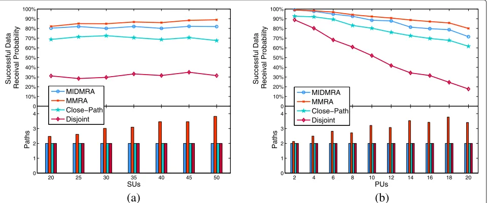
Therefore, MIDMRA, closeness, and the space and spectrum disjoint protocols in [13] and the multi-layer-based multi-path routing algorithm (MMRA) are employed. For short, the spectrum and spectrum disjoint protocols are abbreviated as “disjoint.”
In this simulation, these two mechanisms are compared on successful data receival rate since they have differ-ent routing approaches. And detailed simulation settings are stated in Table 1. Five hundred packet data would be send at a speed of 10 packets/s, which means that each packet would cost 0.1 s from one node to another. When PU arrives, the links between the nodes in PU’s inter-ference range must stop data transmission and hop to other channels; channel hopping time is the delay which is generated by communication reconfiguration on other channels. While timeout threshold represents the limit time of packet loss.
Then, by simulating 100 iterations as those in previous experiments, the results are depicted as Fig. 7. The upper part of figure draws successful data receival rate, and the
lower part is the average selected paths amounts which are utilized in simulations.
Figure 7a shows successful data receival rate when the amounts of CR nodes are different. MIDMRA, closeness, and disjoint maintain stable performances through dif-ferent network densities, but the successful data receival rates between them are obvious. MIDMRA has over 10% higher data transmission rate than closeness, which has been proven in previous sections. The disjoint mechanism has the lowest data rate since fixed spectrum channels assignment is acquired. While MMRA has the best per-formance in these mechanisms, but the amounts of paths which are utilized for data transmission are also increas-ing with CR nodes. The cost of MMRA is always higher than others.
Figure 7b depicts out successful data receival rate under different PU amounts. When the amount of PU increase, there is a downward trend in all results, especially for result of disjoint. That is because disjoint does not focus on PU interferences. MMRA and MIDMRA have a small difference on the results; although, MMRA has an advan-tage, which is because more paths are used.
In conclusion, MIDMRA has better performances than closeness and disjoint under single interface CR device environment. MMRA and MIDMRA are applied in dif-ferent environments, the former could get higher results with high cost, while the latter have more adaptability to extreme applications and relatively good results.
5 Conclusions
In summary, the disjoint multi-path routing problem has been addressed under single interface environment through the presented algorithm MIDMRA in this paper.
20 25 30 35 40 45 50
By proposing the mirror image algorithm, the multi-path routing problem is simplified into the single shortest path routing problem. Through using the path selection algo-rithm, a long optimal path is selected in an extended mirror graph, so disjoint multiple paths could be obtained from this long optimal path. Advantages of MIDMRA have been analyzed and proven, simulation results indi-cate that MIDMRA is workable and has better perfor-mance than other routing mechanisms.
On the other side, there also exist some problems and challenges waiting for studying in future:
• PUs’ movements are continuous and random, ordinary “ON-OFF” type definition on spectrum channels occupation is not very appropriate for this question actually, a more precise PUs’ interference estimation method should be studied.
• The purpose of continuous data transmission is the same between this paper and delay tolerance in sparse network. But the different topologies make them hard to share solutions. The disruption on key nodes in sparse networks is a major bottleneck for MIDMRA in sparse networks. The combination between MIDMRA and solutions in sparse networks for settling this bottleneck would be researched. • More comprehensive experiments on real CR
networks test platform would be held.
Acknowledgements
This research is supported by the National Natural Science Foundation of China (Grant Nos. 51475343 and 61672395), the International Science & Technology Cooperation Program, the Hubei Technological Innovation Special Fund (Grant No. 2016AHB005), and the Fundamental Research Funds for the Central Universities (Grant No. 2017III5XZ).
Funding
National Natural Science Foundation of China (Grant Nos. 51475343 and 61672395) are supporting the data acquisition devices and materials; the International Science & Technology Cooperation Program, Hubei
Technological Innovation Special Fund (Grant No. 2016AHB005) is supporting traveling fees abroad on researching this design in France; and the Fundamental Research Funds for the Central Universities (Grant No. 2017III5XZ) is the supporting data analyses.
Authors’ contributions
DZ designed the main body of the algorithm and completed all experiments; QL and LC gave guidance on the ideas of this algorithm and discussed research problems with DZ in the process of the design; WX gave assistance with DZ on the simulations and data analyses; KW discussed with and assisted DZ on writing this paper. All authors read and approved the final manuscript.
Competing interests
The authors declare that they have no competing interests.
Publisher’s Note
Springer Nature remains neutral with regard to jurisdictional claims in published maps and institutional affiliations.
Author details
1School of Information Engineering, Wuhan University of Technology, Wuhan,
China.2Key Lab. of Fiber Optic Sensing Technology and Information
Processing, Ministry of Education, Wuhan, China.3Lab. de Recherche
Informatique (LRI-CNRS UMR 8623), Univ. Paris-Sud, 91405 Orsay, France.
Received: 7 November 2016 Accepted: 26 May 2017
References
1. M Noura, R Nordin, A survey on interference management for
device-to-device (d2d) communication and its challenges in 5g networks. J. Netw. Comput. Appl.71, 130–150 (2016). [Online]. Available: http:// www.sciencedirect.com/science/article/pii/S1084804516300753 2. N Panwar, S Sharma, AK Singh, A survey on 5g: The next generation of
mobile communication. Phys. Commun. Part 2.18, 64–84 (2016). Special Issue on Radio Access Network Architectures and Resource Management for 5G. [Online]. Available: http://www.sciencedirect.com/science/article/ pii/S1874490715000531
3. SJ Darak, S Dhabu, C Moy, H Zhang, J Palicot, A Vinod, Low complexity and efficient dynamic spectrum learning and tunable bandwidth access for heterogeneous decentralized cognitive radio networks. Digital Signal Process.37, 13–23 (2015). [Online]. Available: http://www.sciencedirect. com/science/article/pii/S1051200414003431
4. J Riihijärvi, P Mähönen, M Petrova, What will interference be like in 5g hetnets? Phys. Commun. Part 2.18, 85–94 (2016). Special Issue on Radio Access Network Architectures and Resource Management for 5G. [Online]. Available: http://www.sciencedirect.com/science/article/pii/ S1874490715000506
5. C Cormio, KR Chowdhury, A survey on mac protocols for cognitive radio networks. Ad Hoc Netw.7(7), 1315–1329 (2009)
6. Z Hasan, H Boostanimehr, V Bhargava, Green cellular networks: A survey, some research issues and challenges. Commun. Surv. Tutorials IEEE.13(4), 524–540 (2011)
7. J Mitola, Cognitive radio architecture evolution. Proc. IEEE.97(4), 626–641 (2009)
8. J Mitola, GQ J Maguire, Cognitive radio: making software radios more personal. Pers. Commun. IEEE.6(4), 13–18 (1999)
9. I Beltagy, M Youssef, M El-Derini, inWireless Communications and Networking Conference (WCNC). A new routing metric and protocol for multipath routing in cognitive networks (IEEE, 2011), pp. 974–979 10. M Youssef, M Ibrahim, M Abdelatif, L Chen, AV Vasilakos, Routing metrics
of cognitive radio networks: a survey. IEEE Commun. Surv. Tutorials.16(1), 92–109 (2014)
11. D Zhang, Q Liu, L Chen, W Xu, K Wang, Multi-layer based multi-path routing algorithm for maximizing spectrum availability. Wirel. Netw. 1–13 (2016). [Online]. Available: http://dx.doi.org/10.1007/s11276-016-1377-x
12. M Karmoose, K Habak, M Elnainay, M Youssef, inInternational Conference on Wireless and Mobile Computing, Networking and Communications. Dead zone penetration protocol for cognitive radio networks, (2013), pp. 529–536
13. S Ju, JB Evans, inGLOBECOM - IEEE Global Telecommunications Conference. Cognitive multipath multi-channel routing protocol for mobile ad-hoc networks, (2010)
14. A Valera, WK Seah, S Rao, inProceedings - IEEE INFOCOM, vol. 1.
Cooperative packet caching and shortest multipath routing in mobile ad hoc networks, (2003), pp. 260–269
15. K Wu, J Harms, inIEEE International Workshop on Modeling, Analysis, and Simulation of Computer and Telecommunication Systems - Proceedings. Performance study of a multipath routing method for wireless mobile ad hoc networks, (2001), pp. 99–107
16. H Mustafa, X Zhang, Z Liu, W Xu, A Perrig, Jamming-resilient multipath routing. Dependable Secure Comput. IEEE Trans.9(6), 852–864 (2012)
17. X Zhang, A Perrig, inGLOBECOM - IEEE Global Telecommunications Conference. Correlation-resilient path selection in multi-path routing, (2010)
18. Y Cao, Z Sun, Routing in delay/disruption tolerant networks: a taxonomy, survey and challenges. IEEE Commun. Surv. Tutorials.15(2), 654–677 (2013)
19. J Zhao, X Zhuo, Q Li, W Gao, G Cao, Contact duration aware data replication in DTNs with licensed and unlicensed spectrum. IEEE Trans. Mobile Comput.15(4), 803–816 (2016)
21. E Martins, M Pascoal, A new implementation of yen’s ranking loopless paths algorithm. Q. J. Belg. Fr. Ital. Oper. Res. Soc.1(2), 121–133 (2003). [Online]. Available: http://dx.doi.org/10.1007/s10288-002-0010-2 22. JW Suurballe, RE Tarjan, A quick method for finding shortest pairs of
disjoint paths. Networks.14(2), 325–336 (1984). [Online]. Available: http:// dx.doi.org/10.1002/net.3230140209