Volume 2010, Article ID 634810,8pages doi:10.1155/2010/634810
Research Article
Minimizing SIP Session Re-Setup Delay over Wireless Link in
3G Handover Scenarios
Bongkyo Moon
Department of Computer Science and Engineering, Dongguk University-Seoul, 3-26 Pil-dong, Chung-gu, Seoul 100-715, South Korea
Correspondence should be addressed to Bongkyo Moon,[email protected]
Received 28 July 2009; Revised 31 December 2009; Accepted 29 April 2010
Academic Editor: Ingrid Moerman
Copyright © 2010 Bongkyo Moon. This is an open access article distributed under the Creative Commons Attribution License, which permits unrestricted use, distribution, and reproduction in any medium, provided the original work is properly cited.
The delay in transmitting SIP messages over the wireless link for session resetup at handover is still major bottleneck for interactive multimedia service. In this paper, a proxy agent-based scheme is proposed to minimize the SIP session setup delay over a wireless link in 3G inter-subnet handover scenarios. This scheme is based on the two characteristics. One is that the major factor of SIP session re-setup delay is generally caused by the retransmissions in the unreliable wireless links, and the other is that most of the fields in request messages as well as response messages are duplicated when a set of SIP messages are exchanged during session re-setup procedure. In this scheme, no change is required in the SIP message processing except for the proxy agents in both BS and MH.
1. Introduction
SIP (session initiation protocol) has been used as a signal-ing protocol for enablsignal-ing multimedia session management functions in the Internet. It has also been considered as an attractive mobility management protocol at application layer for heterogeneous networks. Thus it has also been selected as a major protocol in the IMS (IP multimedia subsystem) by the third Generation Partnership Project (3GPP) [1,2]. IMS actually uses the underlying IP network as a universal communication infrastructure and is hereby deployed in various environments such as stationary, mobile, wired, and wireless, regardless of the type of access devices.
Meanwhile, the message size in the SIP becomes larger than that of binary protocol since SIP is text-based protocol. If the link bandwidth in wireless network is not enough and thus the network link is not so fast, the larger size of signaling message will decrease the link efficiency and also degrades service quality. Consequently, the signaling efficiency in IMS has become increasingly important for providing interactive multimedia cellular service such as real-time online gaming or VoIP service in wireless mobile networks. However, it is a challenge to keep signaling delay low in IMS since SIP has text-based nature. This is particularly significant in the presence of lossy, time-variable, and capacity-constrained wireless links. Typically, a 3G radio access network is so
vulnerable to noise as to increase the bit-error rate (BER) over the wireless channel. Thus, a semireliable link-layer retransmission mechanism such as the Radio Link Protocol (RLP) should be used to improve the BER performance over 3G wireless links [3,4].
UAS(CH) UAC(MH)
INVITE
PRACK
ACK
183 SDP
180 Ringing
Visited network
Home network
200 OK
200 OK
Figure1: SIP message exchange for reestablishing the connection between MH and CH.
Typically, most of the fields in request messages as well as response messages are duplicated when a set of SIP messages are exchanged during session re-setup procedure. In order to reduce the delay in transmitting SIP message over wireless link between the MH and the new BS after handover event, MH may extract the only inconsistent fields between the headers in old request message and new request message and then sends the inconsistent fields to the proxy agent over the wireless link between the MH and the new BS, instead of directly sending the CH the complete re-INVITE message. Eventually, the proxy agent on the new BS reestablishes the SIP session between the new BS and the CH using the stored S-SPEC on behalf of an MH. In this paper, therefore, a proxy agent-based session setup scheme is proposed to minimize the SIP session re-setup delay over a wireless link in 3G handover scenarios. First, SIP session setup procedure in IMS is explained. Second, proxy agent-based SIP session setup scheme is proposed. Finally the performance measures and results are presented.
2. SIP Session Setup Procedure in IMS
In IMS, various SIP servers which are called call session control functions (CSCFs) perform the multimedia session control, the address translation function, the voice coder negotiation for audio communications, and the management of the subscriber’s profile [4]. The CSCF plays three roles: the proxy CSCF (P-CSCF), which is the mobile’s first point of contact in the IMS, the serving CSCF (S-CSCF) responsible for the session management, and the interrogating CSCF (I-CSCF), which is responsible for finding the appropriate S-CSCF based on load or capability.
If the mobile host (MH) moves during an SIP session, meanwhile, the SIP user agent (UA) sends an SIP re-INVITE
request message to each one of its corresponding hosts (CHs). In this message, the MH includes its original SIP user identifier and its new IP address in order to inform the corresponding host where it wants to receive future SIP messages [1,10]. The re-INVITE message, triggered by the SIP UA at the new location, also uses the same call identifier as in the original call setup. Moreover, the c (connection) field of the SDP header contains a description of the session in order to redirect the data traffic flow towards its new location.
In a typical mid-call SIP handover scenario for 3G access, however, the MH needs to be attached to the 3G wireless access networks before sending the re-INVITE message. In particular, the MH reinvites the CH to its new temporary address by sending SIP INVITE message through the P-CSCF, the I-P-CSCF, and the S-CSCF servers. Once the CH gets the updated information about the MH, it sends an acknowledge message while starting to send data [2, 4]. Hence, the session setup delay is mainly caused by the message exchanges that occur for the SIP location update and SIP INVITE request after an MH attaches to a new access network. Since SIP is basically a transactional protocol in the sense that an SIP transaction consists of a single request and any response to that request, the SIP session establishment consists of various transactions.Figure 1illustrates the SIP message exchange for reestablishing the connection between the MH and the CH when the MH is in the visited network and the CH is directly connected to Internet.
3. Proxy Agent-Based SIP Session Setup Scheme
INVITE message sent by RP SIP Spec message
INVITE message sent by MH Ok message
Message sent by MP Message sent by RP
Cell 1 Cell 4
S-Spec (1a) S-Spec (1b)
INVITE (2)
Handover (5)
3)
Remote proxy Internet
INVITE (7)
INVITE (1)
Mobile proxy GGSN
SGSN/BSS
Remote proxy (RP)
SGSN/BSS
Mobile proxy (MP)
GGSN CH
MP message (6) RP message
(9)
P-CSCF P-CSCF
S-CSCF
I-CSCF SIP Server
I-CSCF
S-CSCF
Home network Visited network
OK (3)
OK (8)
OK (4)
Figure2: SIP Session re-Setup by a remote proxy on behalf of MN.
inter-subnet handover scenario. All BSs located together with SGSN (serving GPRS support node) actually have proxy agents, which play a significant role in processing SIP session request message triggered by the MH or the CH. That is, when an SIP session is initiated by the MH or the CH, the proxy agent on the BS, which the MH is attached to, sends an SIP session specification (called S-SPEC) message to a set of possible BSs (called M-SPEC) to which the MH may visit in next step. Hence, the proxy agent on the BS needs to discover the IP addresses of the neighboring BSs in the M-SPEC. The existing solutions to maintain and create M-SPEC can actually be found from a lot of previous works [11–15].
Typically, an INVITE message has most of the fields defined in SIP header and the essential descriptions in SDP body, and a 200 OK status code message also has the important header fields. Hence, the S-SPEC can actually be constructed with INVITE message and 200 OK status code message exchanged when the session is initiated. More specifically, when the MH is a sender, the S-SPEC message consists of INVITE message requested from the MH and the OK message responded from the CH. When the MH is a receiver, the S-SPEC has the opposite SIP message. Thus, SIP session objects in S-SPEC are eventually stored at the newly
discovered BSs in the M-SPEC. In other words, when an MH establishes an SIP session via a current BS, the proxy agent on the BS sends the S-SPEC of the session to the remote proxy agents on the candidate BSs in MH’s M-SPEC. In addition, since installing S-SPEC into the remote proxy agents on the candidate BSs in the M-SPEC can actually be performed in parallel with data transmissions right after the SIP session is established, the extra load due to S-SPEC installation can be ignored in measuring SIP session setup delay.Figure 2shows that a remote proxy agent on the new BS reestablishes the SIP session by using the S-SPEC.
INVITE
ACK
200 OK MP message
MP message RP message
(a) New SIP message exchange sequence between the MH and the CH
UAC
MP agent
200 OK
RP message
SIP UA
RP agent
INVITE/ACK
200 OK
MP message
BS(SGSN) MH
INVITE/ACK 200 OK
INVITE/ACK
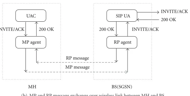
(b) MP and RP message exchange over wireless link between MH and BS
Figure3: Message exchange for the reestablishment of the connection via new BS right after inter-subnet handover.
is, the proxy agent on the BS reestablishes the SIP session between the new BS and the CH using the stored S-SPEC on behalf of an MH. No change is required in the SIP message processing except for the proxy agents in both BS and MH.
Figure 2shows that a proxy agent reestablishes the SIP session on behalf of an MH by using the S-SPEC. In this figure, the MH’s M-SPEC can be changed dynamically while the SIP session is open. After reestablishing SIP session seamlessly during handover event, the S-SPECs stored in old remote proxy agents except the current proxy agent are cleared, and instead, S-SPEC message of the flow session is sent to remote proxy agents in new M-SPEC.
3.3. MP and RP Messages over Wireless Link. Typically most of the fields in request messages as well as response messages are duplicated when a set of SIP messages are exchanged during session setup procedure. In the proposed scheme, the proxy agent on the MH finds a few inconsistent fields between the old INVITE message and the re-INVITE message generated by SIP UA and then sends the new BS an MP (mobile proxy) trigger message over the wireless link. The MP message actually contains the inconsistent fields (e.g., CONTACT: new IP address of the MH), Call-ID, and so on, instead of complete SIP re-INVITE message. Then, a proxy agent on BS, on behalf of SIP UA on the MH, initiates SIP session setup procedure by sending the CH the complete re-INVITE message, which is updated by the information deployed newly in inconsistent fields. Similarly, in the case of OK message sent from the CH, the proxy agent on BS finds the inconsistent fields between the new OK message and the old OK message and sends the MH an RP (remote proxy)
trigger message which contains the only inconsistent fields, instead of complete OK message. The proxy agent on the MH then constructs the complete OK message by updating with the new fields sent from the BS and forwards the message to its SIP UA. Therefore, the delay for transmitting SIP messages over the wireless link can be minimized.Figure 3 shows the message exchange for the reestablishment of the connection via new BS right after inter-subnet handover. Figure 3(a) presents new SIP message exchange sequence between the MH and the CH, and Figure 3(b) brings up the stack overview for MP and RP message exchange over wireless link between MH and BS.
Call-ID
Start line of each SIP message New contact field Other option fields
Figure4: Example of the essential fields in MP (RP) message format.
session from the SIP session objects stored already on the new BS. This result finally causes the proxy agent on the BS to send re-INVITE message for SIP session setup with the new IP address as contact address and the same Call-ID as in the original call setup. Eventually, the proxy agent on the new BS reestablishes the SIP session between the new BS and the CH using the stored S-SPEC on behalf of an MH, and thereby the CH starts to send data after updating information about the MH. Consequently, complete SIP message exchange can be omitted over one-hop wireless link after handover since a proxy agent on the BS promptly sets up the SIP session on behalf of the MH. This can reduce the signaling overhead over one-hop wireless link and thus significantly minimize end-to-end SIP session re-setup delay.
4. Numerical Modelling and
Performance Analysis
4.1. Modelling of the Proposed Scheme. The message process-ing for SIP session setup may take considerable time due to the queueing of the SIP messages in the MH, the intermediate servers (e.g., P-CSCF, I-CSCF, S-CSCF), and destination servers. The major queueing delays can be roughly estimated using the classical queueing theory based on waiting time formulas. The assumptions and analytic method in this section heavily rely on the previous works [3,4]. In order to compute the queueing delay, thus an M/M/1 queueing model can be deployed for the MH and the CSCF servers and a priority-based M/G/1 model for the destination server. That is, the MH and the CSCF servers perform dedicated jobs, but the destination server may serve a variety of non-SIP related tasks as well as the SIP messages.Figure 5presents queueing model for analyzing the delay in SIP session re-setup procedure in 3G handover scenario.
Meanwhile, wireless access link introduces major delays in comparison with the queueing and transmission delay over the backbone networks. In other words, the SIP session re-setup delay after handover is limited by the transmission of SIP signaling messages over erroneous and bandwidth-limited wireless links. Since the RLP can be typically used to improve the BER performance over 3G wireless link, the delay model [3, 4] for frame and packet transmission can be used in order to compute the delay for transmitting SIP messages over a wireless link under various link error conditions.
For the analysis of transmission delay with RLP, several parameters need to be defined. p is the probability of an RLP frame being in error in the air link. Cij represents the first frame received correctly to the destination at the ith retransmission of the jth retransmission trials. That is, the missing frame has been lost up to the (j-1)th retransmission trial and up to the (i-1)th retransmissions in the jth trial. Hence, the probability of transmitting
a frame successfully at the ith retransmission of the jth retransmission trials after frame transmission error is given as P(Cij) = p(1−p)2((2−p)p)j(j−1)/2+i−1. Therefore, the probability of transmitting a frame successfully over the air link with RLP operating underneath is given asPf =1−p+
n
j=1
j
i=1P(Cij) = 1−p(p(2−p))n(n+1)/2, wherenis the
maximum number of RLP retransmission trials.
Considering the RLP retransmissions, the frame prop-agation delay is increased from D to D and thus the delay in transmitting a packet containing k frames over the RLP is given by D = D+ (k−1)τ + (k(Pf −(1−
Dis the end-to-end frame propagation delay over the air link, kis the number of frames for a packet transmitted over the air, andτis the interfame time of RLP.
Since the SIP messages are assumed to be sent over TCP, a delay model for TCP transmission over wireless links is required. According to the model used and the results reported in [3], the delay to transmit a TCP segment considering ofkframes over a radio link with RLP is given byRLP wireless = D+ (2Dq(1−q)/(1−qNT))[1 + 4q(1−
(2q)NT−2)/(1−2q)−q(1−qNT−2)/(1−q)], whereNT is the
number of TCP retransmissions, andq =1−(1−p)kis the packet loss rate.
Now when we assume that multiple MHs are served by the CSCF servers, the SIP message arrival rate at the MH, λM, is a fraction of the SIP message arrival rate at the CSCF servers,λ:λM ≤ λ. Thus, the average queueing delay (ΔMH)
at the MH is given as 1/(μ−λM), where μ is the service
rate of the SIP message at MH. The average queueing dealys (ΔP-CSCF,ΔI-CSCF, andΔS-CSCF) at the P/I/S-CSCF follow the
same expressionρs/λ(1−ρs), whereρsis the destination and the CSCF server’s loads. The queueing delay (ΔDest) at the
destination is the following: ((1/μs)(1−ρo −ρs) +R)/((1− ρo) + (1−ρo −ρs)) ,ρois the load at the destination for non-SIP messages, andμsis the service rate of SIP messages at the destination. The valueRequals to (λox2o+λsx2s)/2 wherex2o andx2s are the second moments ofμo andμs, respectively.
4.2. Performance Analysis for Session Resetup Delay. There-fore, the major queueing delay of an SIP message at the MH, P/I/S-CSCF, and destination server, and the transport delay over the wireless access can be easily determined. From the queueing model in Figure 5, that is, the typical SIP session setup delay (ΔSIP) for 3G can be computed as
ΔSIP = ΔMH +ΔRLP-wireless +ΔP-CSCF +ΔI-CSCF +ΔS-CSCF+
ΔInternet+ΔDest, whereΔInternet is the constant Internet delay
for transmitting the SIP messages. Here,ΔRLP-wireless varies,
reflecting the transport and radio link protocol (RLP) used to convey SIP messages, andΔInternetdepends on the number
P-CSCF MH
MH
MH M/M/1
M/M/1
λ λ
λ λ
CH
M/G/1 I-CSCF
M/M/1 M/M/1 M/M/1
S-CSCF Internet
M/D/1
···
λo
λs
(a) queueing model without remote proxy agent
P-CSCF M/M/1
M/M/1
λ λ
λ λ
CH M/G/1 I-CSCF
M/M/1 M/M/1 M/M/1
S-CSCF Internet
M/D/1
···
MH
MH
MH M/M/1
M/M/1
···
BS
BS
BS
λM
λo
λs
λB
(b) queueing model with remote proxy agent
Figure5: Queueing model for analyzing the delay in SIP session re-setup procedure.
proxy agent-based approach is given asΔMH+ΔRLP-wireless+
ΔBS+ΔP-CSCF+ΔI-CSCF+ΔS-CSCF+ΔInternet+Δdest. And SIP
session re-setup delay using TCCB compression technique is also given asΔMH Comp+ΔRLP-wireless+ΔBS Decomp+ΔP-CSCF+
ΔI-CSCF+ΔS-CSCF+ΔInternet+ΔDest.
5. Results and Discussions
This section presents the average session setup delay for transmitting SIP message over transport and radio link protocols. From the model derived in the previous section, we can know that the average SIP session delay increases exponentially with the FER (frame error rate: p) and is also affected with the number and the size of the message exchanged. For evaluation, the approximate size for each SIP message is obtained from packets captured in the experimental testbed [4]. And the gain in TCCB compression is assumed to be 25%.
In order to derive the value of the number of air link frames (k), we assume that a TCP segment is carried in one packet, the air link frame duration is 20 ms, and the size of one SIP message is 500 bytes. As derived in [3], a 9.6 kbps radio channel can afford 24 (= 9.6×103×20×10−3 ×
1/8) bytes in each frame. Therefore, the number of air link frames in an SIP message isk = 500/24 ≈ 21. Similarly, the numbers of air link frames for 19.2 kbps and 128 kbps channels arek=11 andk=2, respectively.
The values of the delay (D) and the interframe time (τ) are set as 100 ms and 20 ms, respectively. The maximum number of RLP retransmission trials is given as 3. For transmitting SIP message on the top of TCP, the maximum number of TCP retransmissions (NT) is set to 10. Concerning the queueing delay, we assume that the SIP message arrival rate (λ) and the service rate (μ) at the CSCF servers are the same as those at the destination (i.e.,λ=λs,μ=μs). We also assume that the SIP message arrival rate at the MH (λM) is 0.1λ. For the results considering a varying FER, we assume λM = 20 requests/s. For the results considering a varying λM, the FER is kept constant at 0.05 since it is the target FER for VoIP sessions. Due to the varying nature of the Internet delay and the computing power of the intermediate servers, it is difficult to characterize the end-to-end SIP session setup delay at handover. Hence, the Internet delay is assumed to be constant (ΔInternet=200 ms) and some representative values
for the computing capabilities of the servers are assumed as follows:μ=4×10⁻³s,ρ
Frame error rate
(a) The delay variations of SIP session re-setup schemes
Frame error rate
(b) An enlarged scale for the duplicated lines in (a)
Figure6: Comparison of delay for radio channels and session re-setup schemes.
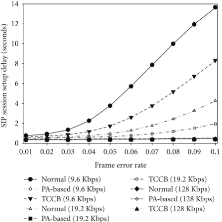
Figure 6(a)shows the delay variations of the SIP session re-setup schemes at handover for radio channels of 9.6, 19.2, and 128 kbps as the channel FER increases.Figure 6(b) presents the SIP session re-setup delay on an enlarged scale for the duplicated lines inFigure 6(a). Here, the SIP message arrival rate at the BS is kept fixed at 200 messages/sec. In this figure, we can see that SIP session re-setup delay becomes larger as radio channel bandwidth is smaller and the FER is larger. From the curves inFigure 6(a) in case of 9.6 kbps and 19.2 kbps radio channel, we can know that the session re-setup delay in the normal SIP becomes much larger than
that of TCCB as the FER increases. However, from the curves inFigure 6(b)in case of 128 kbps radio channel, we can see that the session re-setup delay in TCCB is larger than that of the normal SIP. This is the result caused by the computation delay due to the compression in MH and decompression in BS rather than the delay due to channel bandwidth.
Meanwhile, from the curves in Figures 6(a) and 6(b), the session re-setup delay in PA-based scheme is much less than that of the others since the number of frames for a packet transmitted over the air becomes small. Hence, the delay to transmit a TCP segment considering of frames over a radio link with RLP is also reduced. Particularly, from the curves inFigure 6(b)in case of 128 kbps radio channel, we can know that the session re-setup delay value in PA-based scheme is kept under around 0.34 as FER increases to 0.1. However, the session re-setup delay values in normal SIP and TCCB schemes are kept between 0.34 and 0.40 as FER increases to 0.1. More specifically, in case of 128 kbps radio channel, the number of frames for a packet transmitted over the air becomes smaller, and hereby average packet transmission delay over a radio link with RLP is much more reduced. As a consequence, the difference in delay values among three session re-setup schemes also becomes trivial since the number of frames for a packet transmitted over the air converges on the constant values as the radio channel bandwidth increases. In PA-based scheme, since installing S-SPEC into the remote proxy agents on the candidate BSs in the M-SPEC can actually be performed in parallel with normal data transmissions right after the SIP session is established or signaling message exchanges performed in peer-to-peer manner during the session is being established, the extra load for the sending of the S-SPEC messages and the discovery of the proxies of all the MH’s neighboring cell due to S-SPEC installation can be ignored in measuring SIP session re-setup delay.
Figure 7shows the SIP session re-setup delay at handover as SIP session arrival rate increases. In Figure 6, the SIP message arrival rate at the MH is assumed to beλM = 20 requests/s when the channel FER is varied. Meanwhile, in case of Figure 7, the channel FER is kept constant at 0.05 when the SIP message arrival rate at the P-CSCF server, λ, is varied from 60 to 240 requests/s. From the curves in this figure, we can clearly know that the delay does not increase anymore even though the SIP message arrival rate nearly approaches to the processing rate (μs) at each server. That is, when we consider the total SIP session re-setup delay at handover, we can know that the contribution of queueing delay at each intermediate server is quite trivial in this scenario. Therefore, we can clearly know that the major factor in SIP session re-setup delay may be attributed to the delay caused by the retransmissions in the unreliable wireless links.
6. Conclusions
SIP session arrival rate
Figure7: SIP session re-setup delay for different radio channels.
BSs located together with SGSN actually have proxy agents, which play a significant role in processing SIP session request message triggered by the MH or the CH. This scheme is actually based on the two characteristics. One is that the major factor of SIP session re-setup delay is generally caused by the retransmissions in the unreliable wireless links, and the other is that most of the fields in request messages as well as response messages are duplicated when a set of SIP messages are exchanged during session re-setup procedure. Eventually, since a proxy agent on the BS promptly performs the SIP session re-setup on behalf of the MH, the complete SIP message exchange can be omitted over one-hop wireless link after inter-subnet handover. As a consequence, this scheme can reduce the signaling overhead over one-hop wireless link and thus significantly minimize end-to-end SIP session re-setup delay.
In this scheme, since installing S-SPEC into the remote proxy agents on the candidate BSs in the M-SPEC can actually be performed in parallel with normal data trans-missions right after the SIP session is established or signal-ing message exchanges performed in peer-to-peer manner during the session are being established, the extra load for the sending of the S-SPEC messages and the discovery of the proxies of all the MH’s neighboring cell due to S-SPEC installation at session setup can be ignored in measuring SIP session re-setup delay. No change is required in the SIP message processing except for the proxy agents in both BS and MH.
Acknowledgment
This work was supported by the Korea Research Foundation Grant funded by the Korean Government (MOEHRD, Basic Research Promotion Fund: KRF-2006-331-D00357).
[1] J. Rosenberg, H. Schulzrinne, G. Camarillo, et al., “SIP: Session Initiation Protocol,” RFC3262, IETF, June 2002.
[2] A. Kist and R. Harris, “SIP Signaling Delay in 3GPP,” in
Proceedings of the 6th International Symposium on Com-munications Interworking of IFIP—Interworking, Fremantle, Australia, October 2002.
[3] N. Banerjee, W. Wu, K. Basu, and S. K. Das, “Analysis of SIP-based mobility management in 4G wireless networks,”
Computer Communications, vol. 27, no. 8, pp. 697–707, 2004. [4] H. Fathi, S. S. Chakraborty, and R. Prasad, “Optimization of
SIP session setup delay for VolP in 3G wireless networks,”IEEE Transactions on Mobile Computing, vol. 5, no. 9, pp. 1121– 1132, 2006.
[5] H. Fathi, S. S. Chakraborty, and R. Prasad, “On SIP session setup delay for VoIP services over correlated fading channels,”
IEEE Transactions on Vehicular Technology, vol. 55, no. 1, pp. 286–295, 2006.
[6] M. A. Melnyk, A. Jukan, and C. D. Polychronopoulos, “A cross-layer analysis of session setup delay in IP Multimedia Subsystem (IMS) with EV-DO wireless transmission,”IEEE Transactions on Multimedia, vol. 9, no. 4, pp. 869–880, 2007. [7] S. Pack and H. Lee, “Call setup latency analysis in SIP-based
voice over WLANs,”IEEE Communications Letters, vol. 12, no. 2, pp. 103–105, 2008.
[8] A. Munir, “Analysis of SIP-based IMS session establishment signaling for WiMax-3G networks,” inProceedings of the 4th International Conference on Networking and Services (ICNS ’08), pp. 282–287, Guadeloupe, France, March 2008.
[9] H. Wook and S.-G. Kang, “Improvement of link efficiency by compressing SIP signaling messages with SigComp,” in
Proceedings of the 10th International Conference on Advanced Communication Technology (ICACT ’08), pp. 1314–1317, Pyeongchang, South Korea, February 2008.
[10] I. Majumdar, V. Kenneally, and D. Pesch, “Improving SIP call control performance through message compression— the TCCB algorithm,” in Proceedings of the International Conference on Signal and Image Processing (SIP ’03), Paris, France, January 2003.
[11] C. H. Rokitansky, “Knowledge based routing strategies for large mobile networks with rapidly changing topology,” in Proceedings of the International Conference on Computer Communication (ICCC ’99), New Delhi, India, November 1990.
[12] S. Okasaka, S. Onoe, S. Yasuda, and A. Maebara, “A new location updating method for digital cellular systems,” in
Proceedings of the 41st IEEE Vehicular Technology Conference, pp. 345–350, Saint Louis, Mo , USA, May 1991.
[13] B. R. Badrinath, T. Imielinski, and A. Virmani, “Locating strategies for personal communication networks,” in Proceed-ings of the Workshop on Networking of Personal Communica-tions Appliances, December 1992.
[14] H. Xie, S. Tabbane, and D. Goodman, “Dynamic location area management and performance analysis,” inProceedings of the 43rd IEEE Vehicular Technology Conference, pp. 536–539, Atlanta, Ga, USA, May 1993.