R E S E A R C H
Open Access
Routing strategy in disconnected mobile ad hoc
networks with group mobility
Ling Fu Xie, Peter Han Joo Chong
*and Yong Liang Guan
Abstract
Most of the current proposed routing protocols in delay-tolerant network (DTN) are designed based on the entity mobility. In this article, we consider the routing in DTN with group mobility, which is useful in modeling those cooperative activities. The new proposed routing scheme is called group-epidemic routing (G-ER). G-ER is designed on the basis of one DTN protocol called epidemic routing (ER). In G-ER, two strategies related to the unique characteristics of the group mobility have been proposed to greatly improve ER. The first is to treat each group as a single node and exchange packets between groups instead of individual nodes. Thus, the resource-consuming problem of ER could be much alleviated. In the meantime, exchanging packets between two groups could speed up the packet delivery. The second is the buffer sharing inside a group, which is supported by the cooperative nature in group mobility. Moreover, we specifically propose a group dynamic model for group mobility to realize group splitting and merging. The performance of G-ER is studied by extensive simulations and compared with ER and dynamic source routing (DSR). Results show that G-ER outperforms ER and DSR in different network scenarios even with group dynamics.
Keywords:Delay-tolerant network, Group mobility, Group-epidemic routing, Epidemic routing, Group dynamic model
1. Introduction
Group mobility has been taken as the basis for the rou-ting scheme design in mobile ad hoc networks due to its realistic meanings. Different from entity mobility, in which nodes move independently among each other, group mobility assumes some nodes move in a group, and they have similar moving behavior. Thus, the topo-logy within a group will keep connected most often. Group mobility could be extracted in many practical scenarios, especially in those cooperative scenarios. For example, a group of soldiers generally move together to execute a common task in the military operation. So far, a number of group mobility models have been proposed, like Reference Point Group Mobility (RPGM) [1] and Community-Based Mobility [2]. Other group mobility models could be found in [3].
Many routing schemes [4-6] for group mobility models have been proposed. These routing schemes make use of some features of group structure for the ease of routing.
Since group members inside a group are assumed to be close to each other, these routing schemes aim to send a packet to the group leader of a group rather than to an exact destination node of a group member. Such a de-sign reduces the complexity of route set-up and main-tenance. However, these routing schemes could work effectively only when there exists a complete path or route for any source and destination pair. In other words, if such a complete path cannot be found or the network is disconnected, they will fail to work [7]. Actu-ally, the network disconnection will happen in group mobility when each group is with relatively small group radius or group coverage [7]. Consequently, a new ting strategy, called delay-tolerant network (DTN) rou-ting [8], was proposed to make the packet delivered successfully in such a disconnected network at the cost of longer delay.
DTN routing employs the store–carry–forward ap-proach to deliver packets. Most proposed DTN routing protocols fall into two different types; purposeful move-ment routing and opportunistic routing. In purposeful movement routing [9-11], the node carrying the data * Correspondence:[email protected]
School of Electrical and Electronic Engineering, Nanyang Technological University, Singapore, Singapore
packet will move purposely to get closer to the destin-ation or to get connected to the destindestin-ation. Generally, this will require the location knowledge of the destin-ation. Different from the purposeful movement routing, opportunistic routing assumes all mobile nodes will fol-low their original moving plans, carrying the packets, and waiting for the opportunity to deliver them to those nodes which will get connected to the destinations. The opportunistic routing could be further classified into three sub-classes; deterministic routing, flooding-based routing, and flooding-controlled-based routing. The de-terministic routing [12,13] chooses the next node to carry the packet based on the known future topology change. This future topology change could be obtained by learning the future nodes’ movements. In the flooding-based routing [14], each packet will be dissemi-nated to every node in the network in hope that those nodes carrying the copies of this packet could meet the destination later. However, with the increasing of the node number in the network, the problem of overhead caused by the flooding or the problem of the resources like buffer size needed for the flooding emerges. Hence, some flooding-controlled-based routing schemes [15-19] are proposed to reduce the overhead or the resources in need by restricting the number of copies of each packet. In the extreme case, no copy of a packet will be gener-ated. This is generally achieved by delivering the packet to a node which has higher probability to meet the des-tination [16,17].
Besides, some previous studies [20-22] apply clustering to DTN to improve network performance. Thomas et al. [20,21] and Dang and Wu [22] consider the scenario in DTN where some nodes under entity mobility may stay close to each other for some time and thus they can form a cluster. Making use of this vicinity among the nodes in one cluster for packet delivery could improve the routing performance. For example, Thomas et al. [20,21] employ on-demand ad-hoc routing to deliver packets quickly within the cluster; nodes in the same cluster in [22] are required to share their contact pro-babilities so as to find a better next hop to carry the packets.
So far, those DTN routing schemes introduced above, including the cluster-based DTN schemes, target for en-tity mobility and they cannot perform effectively in DTN with group mobility. This is because group mobility is different from entity mobility and thus, accordingly some specific mechanisms can be proposed for it to im-prove routing performance. We will present these spe-cific mechanisms for group mobility while introducing our proposed scheme below.
The objective of this article is to propose a routing scheme which can perform effectively in group mobility scenarios by making full use of the characteristics of the
group mobility. After understanding of various DTN routing strategies, we find that the strategy of epidemic routing (ER) [14] well suits the group mobility, and then propose group-epidemic routing (G-ER) for group mobility.
We have proposed two important mechanisms in G-ER, both in the form of cooperation inside the group. The first mechanism is the group-based packet exchange. Similar to [20-22], by treating each cluster/group as a single node, G-ER is a two-layer routing, including the inter-group routing and intra-group routing. The strategy of ER is adopted for the inter-group routing to exchange packets between groups, and a table-driven routing is employed for the intra-group routing to handle the packet delivery inside the group. Importantly, we employ the group-based packet exchange to expedite the packet delivery in this two-layer routing: when two nodes from two groups meet each other, other members in these two groups will also take this chance to deliver packets to the neighboring group. In contrast, the packet exchange in all DTN schemes mentioned above takes place only between two contacting nodes, which we refer to as the node-based packet exchange. The second mechanism is the buffer sharing inside a group, which is used to reduce the buffer requirement at one node in G-ER. This buffer sharing could be well supported by the nature of a group, i.e., the cooperation among group members. In addition, we study the performance of G-ER under group dynamics and find that the impact of group dynamics can be reduced by some proper buffer resource allocation in one group. Extensive simulations are conducted to show the advan-tages of G-ER in different scenarios, even with group dynamics.
2. Review of ER 2.1. Summary of ER
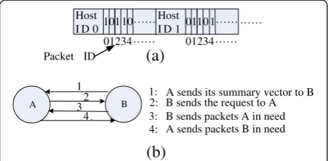
ER [14] was proposed to support packet delivery in dis-connected ad hoc networks. Since the network is discon-nected most of time, buffering the packet and waiting for the opportunities to meet the destination is the es-sential strategy in ER. Moreover, in order to increase the probability to meet the destination for a packet, letting other intermediate nodes carry the copies of this packet is the second mechanism in ER. There are two steps in-volved in ER for the packet delivery.
one node are assigned with different PIDs. Thus, these two indexes make one packet unique in the network. Then, by letting one node, say node A, send its SV to the other one, say nodeB, nodeBcan determine the dif-ferent packets between them by comparing A’s SV to its local SV.
Second, the data packet exchange is initiated imme-diately after the SV comparison in the first step. Once the node in the first step, i.e., node B, determines the differentpackets, it can send a request to nodeAfor the packets it has not received, and send to node A the packets which node A has not received. By doing this, the packets could be disseminated to all nodes and their copies could be stored in all nodes. Figure 1b shows the SV and data packet exchange between nodesAandB.
To avoid the frequent SV exchange between the same two nodes, each node in ER keeps the record of the con-tacts with other nodes. With this record, only the node, which has not been seen for certain duration, is considered a new neighbor with which the SV exchange is activated. We set this duration 5 s in our simulation for ER.
2.2. Reasons for selecting ER in group mobility
Among all those DTN routing strategies mentioned above, ER is chosen for group mobility for two reasons. First, we consider the group mobility scenario where neither the location of the mobile node nor the future movement plan could be known or available. Impor-tantly, ER does not require any prior node location or node moving information. Second, although ER is a resource-consuming protocol, especially in the network with large node number, it can achieve optimal perfor-mance given the adequate resources, such as the buffer size and bandwidth. In fact, the sensitivity of ER to the resource in terms of buffer could be largely alleviated in group mobility by treating each group as a single node and disseminating one copy of one packet to one group, because the group number is generally much less than the node number in the network. Due to these reasons, our proposed G-ER is designed based on ER.
3. G-ER for group mobility
In this section, we present the proposed G-ER for the group mobility, including the intra-group routing, the inter-group routing, the node buffer management, and the buffer sharing mechanism. Before we illustrate each of them, we first highlight the group structure mainten-ance under which G-ER works.
3.1. Group structure maintenance in group mobility model
3.1.1. Group formation
The criterion for the group to be formed in group mo-bility differs from that in entity momo-bility. First, nodes in group mobility, with the same interests or mission [1,2], are generally grouped together, whereas nodes in entity mobility, which are physically close to each other, will be grouped together [20-22]. Thus, the group membership of each node in group mobility is already determined be-fore it joins the network, and most of time it will keep the same group membership. For example, members from a medical group should most of time work within their team in a practical disaster relieve. Second, the leader or the commander in each group should be desig-nated in group mobility before the group is formed, whereas it is randomly selected in entity mobility [20-22]. Actually, this criterion for the group formation in group mobility is applicable to many scenarios, like the troop formation in the military field.
3.1.2. Group dynamics
Although we state that the group structure or group membership in group mobility could keep more stable than that in entity mobility, we also consider its dynam-ics for no loss of generality. Group dynamdynam-ics means group splitting or merging could take place. For group dynamics, we assume that the group leader is robust enough not to be down and only group members will change their memberships if necessary. Here, we propose a simple method for group splitting and mer-ging in group mobility. First, except the group leader, each group member will randomly generate a probabil-ity, Pr, when it is contacting with other group members from other groups. If this generated Pr is larger than a threshold,Tgs, and the current total number of nodes in its group is larger than Gmin, it will leave its current group and join this new group. Otherwise, it will still stay in the current group. Note thatTgsreflects the sta-bility of each group: a larger Tgs means a more stable group structure. The parameter Gmin, which represents the minimal node number in each group, is used to model some real scenarios, in which each group requires some certain members to function properly for its mis-sion or task.
1: A sends its summary vector to B 2: B sends the request to A 3: B sends packets A in need 4: A sends packets B in need
3.2. Intra-group routing strategy
The intra-group routing is used to route a packet to a des-tination or an intermediate node within a group. That packet can be generated from a particular node and des-tined to another node within the same group, which is re-ferred to as theintra-group packet. Or that packet can be generated from a particular node and destined to another node in a different group, which is referred to as the inter-group packet. The intra-group packet will be delivered to the destination node by the intra-group routing. The inter-group packet is first routed to its destination group by the inter-group routing and then, it will be routed to the destination node by the intra-group routing. One im-portant issue here is how a node could determine whether a received packet is destined to a node in its group or to a node in other groups. This can be achieved by checking the destination of that packet from the node’s member list, Listmember, which is used to record all nodes in the same group. Thus, if the destination of a packet appears in Listmember, it will be routed by the intra-group routing. Otherwise, the packet will be buffered.
Due to the full connectivity within a group, any rout-ing protocol aimed for connected networks, such as the table-driven routing or on-demand routing, could be used for the intra-group routing. However, it is more suitable to use the table-driven routing because it is rea-sonable to assume the size of each group in reality is within few hops for the ease of cooperation. Hence, in G-ER, destination-sequenced distance vector routing (DSDV) [23] is adopted for the intra-group routing. Note that each node is required to include its group membership, i.e., group ID (GID), in its DSDV routing update, and only the node with the same GID receives this routing update. Moreover, by receiving this routing update, each node can update its Listmemberin case that some new member joins.
3.3. Inter-group routing strategy
The inter-group routing is to forward an inter-group packet to its destination group which contains the des-tination node of that packet. Different from ER, which floods each packet to each node, G-ER disseminates a packet to each group rather than each node. G-ER han-dles all nodes belonging to a group as an individual node and thus, each group will store only one copy of each inter-group packet. Consequently, the resource-consuming problem in ER could largely be mitigated. The inter-group routing consists of three procedures as explained in the following sections.
3.3.1. Group summary vector update broadcast mechanism within a group
Similar to SV in ER as shown in Figure 1a, group sum-mary vector (GSV) is used to determine different
received packets between two groups when they meet each other. However, different from SV, which only re-cords the received packets for one node, GSV rere-cords all packets received by all nodes within a group, not only one node. Hence, GSV at each node is actually the con-catenation of SV from all nodes in its group. Further-more, only inter-group packets need to be recorded in GSV because intra-group packets will not be exchanged between groups.
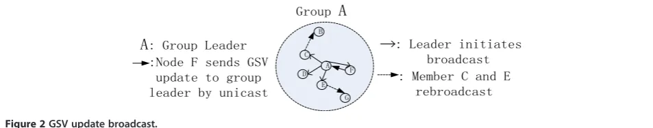
Whenever a node receives a new packet, that node needs to notify other nodes in its group of its newly re-ceived packet timely in order to let them know all packets its group has received. Thus, a GSV update broadcast mechanism should be introduced to quickly inform any newly received packet to each group member and the leader. The GSV update broadcast is described as follows:
(1) Each group leader initiates GSV update broadcast, instead of letting each member simply broadcast the update within the group. The reasons are explained as follows. First, we consider IEEE 802.11 MAC standard to be used in G-ER, in which the hidden terminal problem exists or no RTS/CTS exchange is used for broadcast. Thus, letting each member simply broadcast GSV update will increase the possibility of collisions between DSDV routing update and GSV update, which will impact the intra-group routing performance. Hence, to reduce the collision possibility in G-ER, only the leader is required to initiate this broadcast. Second, we believe that the leaders in reality are able to keep in touch with their members most of time. Thus, the GSV update broadcast initiated by the leaders can reach their members quickly. Hence, when one member updates its GSV after receiving some new packets, it will send a packet to its leader by unicast to inform these newly received packets. Then, upon receiving this packet from the member, the leader will update its GSV and broadcast this updated GSV to others in its group. This GSV update broadcast includes the updated GSV and the IDs of all 1-hop neighboring members of the leader. This neighbor information is used to help members determine whether they should rebroadcast the received GSV update, which we will see below. (2) Once a member receives the GSV update broadcast
avoid the unnecessary rebroadcasting so as to save the overhead incurred in the GSV update
broadcast. Figure2illustrates this GSV update broadcast inside a group in G-ER.
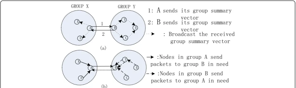
3.3.2. GSV exchange and group-based packet exchange When two nodes from two groups meet each other, the packet exchange will take place. Different from [20-22], in which only the two contacting nodes exchange their packets, G-ER involves with other group members for packet exchange between two contacting groups to ex-pedite the packet delivery. This is so-called the group-based packet exchange, which is a form of cooperation inside the group, and it is described as follows.
(1)GSVis exchanged between two contacting nodes to determine which packets should be exchanged between them. Different from the SV exchange in ER, which requires only one node to send its SV to the other node, each node in G-ER is required to exchange its GSV to the other. Figure3a shows that two nodes,AandB, from two groups in contact, exchange their GSVs.
(2) Once GSV from another group is received by a node, e.g., nodeA, it will be broadcast within the same group to nodesFandGas shown in Figure3a for the preparation of the data packet exchange later. GSV broadcast fromAis similar to the GSV update broadcast inSection3.3.1 that the 1-hop neighbor information is included to avoid the unnecessary rebroadcast. Note that G-ER does not require each member in the two contacting groups to successfully receive the GSV from the
neighboring group.
(3) By comparing the received GSV to the local kept GSV, the two member nodes in contact, e.g., nodes AandBin Figure3, determine which packets should be sent to each other. Since some packets which are supposed to send to another group may not be stored in these two member nodes, they will be sent by other group members in the two contacting groups where these packets are stored. For example, in Figure3b, nodeAmay not store some packets which are supposed to send to node
B, but nodesFandGstore them. Then, upon receiving the broadcast GSV from nodeAin the second step above, nodesFandGwill forward those needed packets to nodeA. The packet forwarding between nodesAandForGis based on DSDV. After nodeAreceives these packets, it can forward them to nodeBor any other member in contact in groupY. But, if the link betweenA andBis broken, these packets sent by nodesFand Gwill finally be dropped.
(4) The GSV update procedure is different for
intermediate group and destination group. When a new packet arrives at a node of an intermediate group, that node will first update the GSV by adding the new PID into its GSV and then inform the new received packet to its leader later. However, when a new packet arrives at a node of the
destination group, the GSV will not be updated until that packet is received by the destination node using the intra-group routing. Since the newly received packet could be dropped during intra-group routing, it is safer to allow only the destination node to update its GSV. That is, if the newly received packet is dropped during intra-group routing, the destination intra-group would have a chance to receive the same packet again from other groups later.
As a matter of fact, in some situation the principle of one copy of an inter-group packet for one group could be violated, which means the same packet could be sent to the same group for more than once. For example, if several member pairs from groups X and Yare in con-tact simultaneously, the members in these two groups will be requested for packet transmission for multiple times, which will cause one packet to be transmitted repeatedly. To deal with this problem, we propose a method to guarantee the dissemination principle in G-ER by recording the traversed groups in the packet header. Whenever a packet from group Xis ready to be sent to another group Yin contact, the GID of groupY will be recorded in the packet header. Thus, the same packet will not be sent to groupYagain by group X be-cause members from group X can find out that the
packet has been sent to groupYalready by checking the packet header. Moreover, the information of traversed groups will be used for the buffer management later.
Similar to ER, G-ER implements a time duration to avoid frequent GSV exchange between two groups. It is roughly achieved by letting each node record the time of last GSV exchange with any other group. If the time dif-ference between the current time and the last exchange time is less than this duration, the GSV exchange will not be initiated between these two groups. For fairness, we also set this duration 5 s in G-ER same as that in ER.
3.4. Node buffer management
Here, the node buffer management is introduced to G-ER to further guarantee the packet delivery. Since there is no way to avoid packet drop given inadequate buffer size, how to selectively drop packets in G-ER is the main concern of our buffer management. We divide the packets into two types for management. The first type refers to the packet to be routed by the intra-group routing, including the intra-group packet and the inter-group packet which has arrived at the destination inter-group. The second type refers to the inter-group packet which has not arrived at the destination group. Two strategies for the buffer management are described as follows.
The first strategy gives higher priority to the first packet type to be kept in the buffer than to the second packet type. The reasons are described as follows: (1) The first packet type could have a better chance for the final delivery because most of time there would be avai-lable routes for them using the intra-group routing. (2) Once this type of packet is dropped, especially the intra-group packet, it will permanently be lost, as opposed to the second packet type.
The second strategy is to first drop the packet in the second type which has the highest probability to be de-livered to the destination. We sort the packets of this second type with the number of the traversed groups in a node’s buffer. The packet with a highest number of
traversed groups will be dropped first, because the higher number of traversed groups for a packet means that more copies of that packet are stored in the net-work and thus, the higher probability that it could have been received by the destination node. Hence, dropping this kind of packet first will not detriment network per-formance. As mentioned earlier in Section 3.3.2, the in-formation of traversed groups is recorded in the packet header whenever it is forwarded to another group. Thus, this information can be used in the buffer management.
3.5. Buffer sharing inside group
The buffer sharing mechanism inside a group is proposed based on another feature of the group. That is, the mem-bers inside a group share the same interests or tasks and they are willing to cooperate with each other. Thus, nodes in one group can share their resources like the buffer to improve network performance. The buffer sharing inside a group works effectively in the scenario where group mem-bers have different buffer utilizations, which we will see in the simulation. It is implemented as follows:
(1) Each group member or leader will periodically broadcast its buffer availability information to all other nodes in its group. This information will be simply included in the DSDV routing updates. The buffer statuses of other nodes learnt by a member or leader are also included in its routing updates. In order to prevent the stale buffer state information, each broadcast contains a sequence number, similar to that used in DSDV routing update.
(2) Once a node receives the buffer update from a group member or the leader, it will record the latest buffer availability of these nodes included in the received update.
such member or leader cannot be found, the packet will be dropped eventually.
3.6. Handling of group dynamics in G-ER
Lastly, how G-ER reacts to group dynamics is intro-duced here. There are four steps to be taken in case of group dynamics.
(1) When a node, sayA, from groupXdecides to leave for another groupY, it will inform its leave to its current leaderXby sending a short messageMleave. Meanwhile, nodeAwill clear its current GSV and its routing table. Then, the packets stored in nodeAwill be unloaded to the neighbors ofAin groupX. Thus, the copies of the packets can be still stored in groupX. (2) Once the leaderXreceivesMleavefrom nodeA, it
will trigger a broadcast of the DSDV routing update to inform other members of nodeA’s leave. Then, other group members in groupXcould update their routing tables andListmemberby receiving the routing update from the leader.
(3) NodeAwill also inform its joining to groupYby sending a short messageMjointo the leaderY.This message will be firstly forwarded to one member in contact in groupY.Then, it can be delivered to the leaderYby DSDV.
(4) Similar to step (2), the leaderYwill also trigger a broadcast of DSDV routing update to inform the newjoiningmember to its members. Then, these members in groupYwill update their routing tables andListmember. Furthermore, the leaderYwill also trigger the broadcast of GSV update, so that the newjoiningnodeAcould initialize its GSV and start to function as a member of groupY.
From the four steps above, we can see that except the packet unloading in step (1), the overhead incurred in the group dynamics is negligible because only the short messagesMleaveandMjoinare required to be sent. More-over, G-ER requires only two groups, like groups X and Y, to know the group membership change of any leaving node such as nodeA. However, in [1,20-22], this group membership change needs to be known to all nodes in the network. Thus, G-ER can reduce the overhead in-curred in group dynamics.
4. Simulation results and analysis
In this section, we study the performance of G-ER in dif-ferent scenarios by simulation in ns-2.33 [24]. Specific-ally, G-ER is mainly evaluated under the following three parameters:
Node buffer size,b: since G-ER, similar to ER, is a replication or flooding-based DTN protocol, we are
interested to see how sensitive G-ER is tob. Therefore, in order to show how much G-ER can lower the buffer requirement for the delivery of all packets, ER is used for comparison [15,16,18]. Group diameter: since the performance of the
intra-group routing in G-ER, i.e., DSDV, is affected by the group scale, we are interested in how DSDV performs in different group scales. We will adjust the group radius,Rg, to form two different group scales in terms of the maximal hops in each group, i. e., the one-hop group and the multi-hop group. Similarly, in order to show how effectively DSDV performs, DSR [25], which is the benchmark in the performance evaluation of traditional ad-hoc routing protocols, is used for comparison.
Group structure stability: given a uniform
distribution forPrfrom 0 to 1, we will set different values ofTgsto form different group structure stabilities. Thus, we can study how G-ER will react to different group structure stabilities.
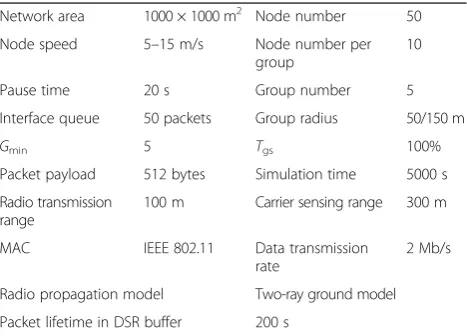
Some important simulation parameters are described as follows. First, the group mobility model we adopt in our study is RPGM [1]. In our scenarios, the movement of each group conforms to the random waypoint mobil-ity, and each group member moves freely within a circle of radius Rg centered by its leader. The node speed is uniformly distributed from 5 to 15 m/s. Once the destin-ation is reached, each node will pause for 20 s. Other pa-rameters relevant to RPGM are given in Table 1, which also shows other simulation parameters. Second, the traffic model used here is similar to that used in previ-ous DTN routing schemes [14,20]. However, we modify it to apply to group mobility such that it generates both intra-group and inter-group traffic so as to evaluate the performances of the intra-group routing and the inter-group routing. In this traffic model, 30 nodes from three groups are selected to generate traffic. Each node from
Table 1 Simulation parameters
Network area 1000 × 1000 m2 Node number 50
Node speed 5–15 m/s Node number per group
10
Pause time 20 s Group number 5
Interface queue 50 packets Group radius 50/150 m
Gmin 5 Tgs 100%
Packet payload 512 bytes Simulation time 5000 s
Radio transmission range
100 m Carrier sensing range 300 m
MAC IEEE 802.11 Data transmission rate
2 Mb/s
Radio propagation model Two-ray ground model
these three groups will take turn to send packets to the other 29 nodes, with two packets for each destination. Thus, each node generates traffic to other 9 nodes within the same group and other 20 nodes in other two groups. The packet generation rate for all source nodes is 4 packets per second. Third, for each point of the re-sults below, the simulation is run for at least 12 times to make it within 90% confidence interval ±10%.
4.1. Performance evaluation of G-ER without buffer sharing
4.1.1. Performance of G-ER at different b and Rgwithout
group dynamics
The simulation results including the 90% confidence inter-val are shown in Figures 4, 5, 6, 7, and 8. Figure 4 shows the intra-group packet delivery ratio,rintra. First, it can be seen thatrintraof all these three routing schemes decreases with the increasing group radius,Rg, because the number of hops for the intra-group packet increases withRg. Most importantly, G-ER basically performs similar to DSR at bothRg= 50 and 150 m. This shows that in spite of the incurred overhead in G-ER, like the GSV update broad-cast, the intra-group routing of G-ER could still perform effectively. Second, we can observe that as compared to ER, both G-ER and DSR are much less sensitive to the buffer size, because a complete route for the intra-group packet in G-ER and DSR could be found most of time in a connected group.
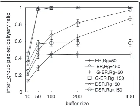
Figure 5 shows the inter-group packet delivery ratio, rinter. First, as expected, it can be seen that G-ER, as com-pared to ER, provides higherrintereven with a small buffer size. Second, it can be observed that rinter of G-ER and DSR is more or less constant when the buffer size is greater than 50, whereas ER is much more sensitive to the buffer size. This is because G-ER forwards onlyone copy of one packet to one group, and DSR does not need to store the copies of the packets. Therefore, G-ER and DSR
require lower buffer size to support the packet delivery. Third, the performances of ER and DSR increase with lar-gerRg, but the performance of G-ER is independent ofRg. As Rg increases, the network becomes more connected, and thus more routes are available for DSR in a more connected network to deliver packets to destination. For ER, as Rg increases, there would be more contact op-portunities between two nodes in two different groups, and hence packets can be more easily deliv-ered to the destinations. For G-ER, due to the low buffer requirement and the efficient intra-group rout-ing even in a multi-hop group, it could deliver most inter-group packets to keep high rinter in most cases.
Figure 6 shows the overall packet delivery ratio, ro, of these three routing protocols, which is the combination ofrintraand rinter. For DSR and ER, both perform better at a largerRg, whereas G-ER always keeps highroexcept in the case of b = 10. Overall speaking, G-ER is able to
10 50 100 200 400
0.7 0.75 0.8 0.85 0.9 0.95 1
buffer size
iintra_group packet delivery ratio
ER,Rg=50 ER,Rg=150 G-ER,Rg=50 G-ER,Rg=150 DSR,Rg=50 DSR,Rg=150
Figure 4Intra-group packet delivery ratio.
10 50 100 200 400 0
0.2 0.4 0.6 0.8 1
buffer size
inter_group packet deliyery ratio
ER,Rg=50 ER,Rg=150 G-ER,Rg=50 G-ER,Rg=150 DSR,Rg=50 DSR,Rg=150
Figure 5Inter-group packet delivery ratio.
10 50 100 200 400
0 0.2 0.4 0.6 0.8 1
buffer size
overall packet delivery ratio
ER,Rg=50 ER,Rg=150 G-ER,Rg=50 G-ER,Rg=150 DSR,Rg=50 DSR,Rg=150
delivery all packets for both radii with very limited buffer size, but the performance of ER severely depends on both buffer size and group radius. For example, at Rg = 150 m, only when b = 400 ER can achieve the optimal performance.
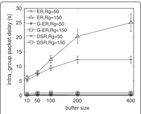
Figure 7 shows the average intra-group packet delay, dintra, for these three routing protocols. Obviously, both G-ER and DSR basically have much lessdintra than that of ER at each Rg. This is because DSDV in G-ER and DSR could provide the available route for intra-group packet most of time. The reason for long dintrain ER is that the period (5 s) introduced to ER to avoid the fre-quent SV exchange actually delays its packet delivery to some extent. Hence, from the similar performance be-tween DSDV and DSR in Figures 4 and 7, we can find that DSDV is an appropriate table-driven routing for the intra-group routing of G-ER when the group size is small or within several hops.
Figure 8 shows the inter-group packet delay, dinter. First, it can be seen that dinter for these three routing schemes decreases when Rg increases because, as explained in Figure 5, a largerRg provides more oppor-tunities for packet forwarding between nodes in differ-ent groups, and thus the inter-group packet can reach the destination group and be delivered at the destin-ation node faster. Second, similar to Figure 5, dinter of G-ER and DSR is more or less independent of buffer size whenb is larger than 50. Interestingly, we can ob-serve that regardless ofRg, whenb< 200, G-ER has lon-ger delay but higher packet delivery ratio (as shown in Figures 5 and 6) as compared to ER. However, whenb> 200, G-ER not only outperforms ER in the packet deliv-ery ratio, but also outperforms ER in dinter. This indi-cates that the group-based packet exchange in G-ER can deliver packets to the destinations faster, be-cause packets stored in those members who are not in contact with the neighboring group could also have the chance to be exchanged. Hence, the group-based packet exchange in G-ER can expedite the packet delivery as compared with the node-based packet exchange in ER.
4.1.2. Performance of G-ER with different Tgsunder group
dynamics
Here, we evaluate the performance of G-ER at different group structure stability, corresponding to different Tgs. The optional value ofTgswill be 1.0, 0.95, 0.9, and 0.85, and Pr, as mentioned above, is uniformly distributed from 0 to 1. We fix the group radius Rg at 50 m, and run the simulation at differentb and Tgswith other pa-rameters remaining the same as used in above.
Figure 9 shows the performance of G-ER at differentb and Tgsin terms ofro. First,roof ER and DSR are inde-pendent ofTgsbecause they are only sensitive to the net-work connectivity, which basically has nothing to do with Tgs. Second, at smaller Tgs, which implies a more dynamic group structure, the performance of G-ER is degraded. With a more unstable group structure, more group members are likely to leave their groups at the same time when two groups meet, so more packets, which are stored in these leaving group members, need to be unloaded to the rest nodes in the same group. Thus, these transferred packets will be dropped easily due to buffer overflow. This is the main reason for the degraded performance of G-ER at lower Tgs. Hence, the improvement of G-ER over ER gradually diminishes as the group structure becomes less and less stable. Third, it can be seen that for a small b, the performance deg-radation of G-ER with Tgs becomes faster. This is be-cause with a smallb at each node, the packets unloaded by those leaving nodes will be dropped more possibly due to buffer overflow. Therefore, from Figure 9 we can find that in our solution the larger buffer size could
10 50 100 200 400
0 5 10 15 20 25 30
buffer size
intra_group packet delay (s)
ER,Rg=50 ER,Rg=150 G-ER,Rg=50 G-ER,Rg=150 DSR,Rg=50 DSR,Rg=150
Figure 7Intra-group packet delay.
10 50 100 200 400 0
50 100 150 200
buffer size
inter_group packet delay (s)
ER,Rg=50 ER,Rg=150 G-ER,Rg=50 G-ER,Rg=150 DSR,Rg=50 DSR,Rg=150
better counteract the negative influence of the group dy-namics to G-ER. Obviously, if there is a policy that the member with smaller buffer size or fewer stored packets is given a higher priority to leave, then it will not only reduce the overhead incurred in the packet unloading, but also decrease the probability for each unloaded packet to be dropped. As a result, this policy will be beneficial to the network eventually. In the followings, we evaluate the effectiveness of such a policy by simulation.
First, we consider the buffer assignment in one group. If the average buffer size for each node is b, then, to keep the total buffer resources in each group unchanged, we assign larger buffer size to half of the nodes including the group leader, with each 1.5b, and assign to the other half with each 0.5 b. Second, the nodes with buffer size 1.5 b (i.e., Gmin nodes in each group in our simulation setting) never leave its group, whereas the other half with smaller buffer size will move among groups. We study the performance of G-ER under this policy atb = 200. From the results, labeled as “G-ER, b = 200, im-proved” in Figure 9, we can find that with this policy, G-ER is much less degraded asTgs decreases, and thus becomes more resilient to the group dynamics.
4.2. Performance evaluation of G-ER with buffer sharing In order to study the performance of buffer sharing, most of the simulation parameters remain the same ex-cept the traffic model, in which group members will generate unbalance traffic. This unbalance traffic model is explained as follows:
(1) Three groups are selected to generate traffic. But only half of the group members from each group will generate packets. This is to mimic the real
scenario where group members may have different tasks or different traffic amounts within a group. (2) No intra-group packet will be generated, because these packets will not be buffered most of time. Each group member from those three groups will send packets to all 40 nodes from other four groups; each with 4 packets. In total, there will be 2,400 inter-group packets generated. The time interval for these packets is also 0.25 s.
Figure 10 shows the performances of G-ER with buffer sharing and without buffer sharing in terms of packet delivery ratio under this unbalance traffic model. From Figure 10, it can be seen that the buffer sharing im-proves the performance of G-ER. The improvement is greater for Rg = 50 m. That means the buffer sharing could work better for a more disconnected network. This is reasonable because with no buffer sharing, more packets will permanently be dropped due to the
buf-10 50 100 200
0 0.2 0.4 0.6 0.8 1
buffer size
overall packet delivery ratio
G-ER,Rg=50 G-ER,Rg=150
G-ER with Buffer Sharing,Rg=50 G-ER with Buffer Sharing,Rg=150
Figure 10Performance of G-ER with and without buffer sharing.
0.85 0.9 0.95 1
0 0.2 0.4 0.6 0.8 1
Threshold, Tgs
overall packet delivery ratio
G-ER,b=50 G-ER,b=200 ER,b=50 ER,b=200 DSR,b=50 DSR,b=200 G-ER,b=200,improved
Figure 9Overall packet delivery ratio with group dynamics.
10 50 100 200
0 20 40 60 80 100
buffer size
average buffer utilization (percent)
G-ER,Rg=50,nonsource G-ER,Rg=50,source
G-ER with Buffer Sharing,Rg=50,nonsource G-ER with Buffer Sharing,Rg=50,source
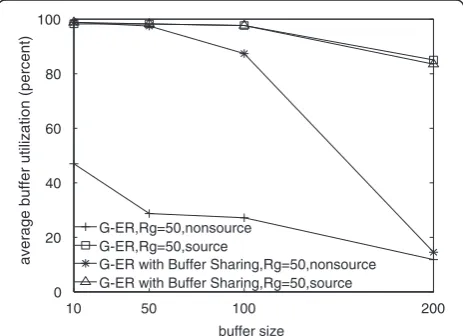
fer overflow in a more disconnected network. Besides, Figure 11 shows the average buffer utilization of one of the three groups which generate traffic for Rg = 50 m. Obviously, in G-ER without buffer sharing, the source members have high buffer utilization, whereas the non-source members have very low buffer utilization. This buffer utilization difference is the main motivation for the proposal of the buffer sharing. We can see from the figure that with buffer sharing, the buffer utilization for non-source members increases significantly. Interest-ingly, for buffer size of 200, the buffer utilization for non-source members is still low because this buffer size is large enough for the source node and thus, the buffers from the non-source members are not needed.
We have also studied the performance of G-ER with buf-fer sharing under the previous balance traffic, finding that the buffer sharing does not provide much improvement to G-ER under that balance traffic. This is because all nodes in one group basically have the same buffer utilization. Hence, it can be seen that our buffer sharing benefits net-work performance when nodes in one group have diffe-rent buffer utilizations.
5. Conclusions
In this article, we have proposed a new DTN routing scheme called G-ER under group mobility scenario with group dynamics. By making full use of the topology fea-ture of the group mobility, two significant mechanisms in the form of cooperation inside the group are pro-posed in G-ER. In G-ER, the table-driven routing is employed for the intra-group routing, and ER’s strategy with our proposed principle of one inter-group packet copy for one intermediate group is adopted for the inter-group routing. The group-based packet exchange and the buffer sharing are integrated into this two-layer routing, which finally makes G-ER outperform ER and DSR in different scenarios. The main features of G-ER are.
(1) Much less buffer resources are needed for the packet delivery as compared to ER. By treating each group as an individual node and disseminating one copy of one inter-group packet for one group, G-ER becomes much less resource-consuming. Generally, the more stable the group structure is, the more benefits G-ER could bring.
(2) G-ER has shorter packet delivery delay than ER because the group-based packet exchange in G-ER increases the opportunities for packets to be sent to other groups.
(3) With larger node buffer size and proper buffer assignment in one group, G-ER could be more resilient to the group dynamics.
Competing interests
The authors declare that they have no competing interests.
Acknowledgments
This study was supported by the research grant DSOCL04020 from the Directorate of Research and Development, Defence Science and Technology Agency, Singapore.
Received: 18 January 2012 Accepted: 1 March 2013 Published: 18 April 2013
References
1. X Hong, M Gerla, G Pei, C Chiang, A group mobility model for ad hoc wireless networks, inProceedings of the ACM International Workshop on
Modeling and Simulation of Wireless and Mobile Systems, (Seattle, WA,
USA, 1999), pp. 53–60
2. M Musolesi, C Mascolo, A community based mobility model for ad hoc network research, inProceedings of the 2nd ACM/SIGMOBILE International
Workshop on Multi-hop Ad Hoc Networks: From Theory to Reality, (Florence,
Italy, 2006), pp. 31–38
3. N Aschenbruck, E Gerhands-Padilla, P Martini, A survey on mobility models for performance analysis in tactical mobile networks. J. Telecommun. Inf. Technol.2, 54–61 (2008)
4. G Pei, M Gerla, X Hong, LANMAR: landmark routing for large scale wireless ad hoc networks with group mobility, inProceedings of the ACM
International Symposium on Mobile Ad Hoc Networking and Computing,
(Boston, MA, USA, 2000), pp. 11–18
5. Y Zhong, K Xu, X Hong, M Gerla, Hybrid landmark routing in ad hoc networks with heterogeneous group mobility, inProceedings of the 2nd International Symposium on Wireless Communications Systems, (Siena, Italy, 2005), pp. 125–129
6. B Zhou, Y Lee, M Gerla, F Rango, Geo-LANMAR: a scalable routing protocol for ad hoc networks with group motion. Wirel. Commun. Mob. Comput. 6(7), 989–1002 (2006)
7. M Zhang, PHJ Chong, Performance comparison of flat and cluster-based hierarchical ad hoc routing with entity and group mobility, inProceedings of
the IEEE Wireless Communication and Networking, (Budapest, Hungary, 2009),
pp. 1–6
8. K Fall, A delay-tolerant network architecture for challenged internets, in
Proceedings of the ACM SIGCOMM, (Karlsruhe, Germany, 2003), pp. 27–34
9. Q Li, D Rus, Communication in disconnected ad hoc networks using message relay. J. Parallel Distrib. Comput.63(1), 75–86 (2003) 10. W Zhao, M Ammar, E Zegura, Controlling the mobility of multiple data
transport ferries in a delay-tolerant network, inProceedings of the 24th
Annual IEEE International Conference on Computer Communications, (Miami,
FL, USA, 2005), pp. 1407–1418
11. MMB Tariq, M Ammar, E Zegura, Message ferry route design for sparse ad hoc networks with mobile nodes, inProceedings of the ACM International
Symposium on Mobile Ad Hoc Networking and Computing, (Florence, Italy,
2006), pp. 37–48
12. R Handorean, C Gill, GC Roman, Accommodating transient connectivity in ad hoc and mobile settings, inProceedings of the Pervasive Computing, (Linz/Vienna, Austria, 2004), pp. 305–322
13. S Jain, K Fall, R Patra, Routing in a delay tolerant network, inProceedings of
ACM SIGCOMM, (Portland, OR, USA, 2004), pp. 145–158
14. A Vahdat, D Becker,Epidemic routing for partially-connected ad hoc networks.
Technical Report CS-2000-06(Duke University, 2000)
15. T Spyropoulos, K Psounis, CS Raghavendra, Spray and wait: an efficient routing scheme for intermittently connected mobile networks, in Proceedings of the ACM SIGCOMM Workshops: Conference on Computer Communications, (Philadelphia, PA, USA, 2005), pp. 252–259 16. A Lindgren, A Doria, O Scheln, Probabilistic routing in intermittently
connected networks, inProceedings of the Workshop on Service Assurance with Partial and Intermittent Resources, (Fortaleza, Brazil, 2004), pp. 239–254 17. Q Yuan, I Cardei, J Wu, An efficient prediction-based routing in
disruption-tolerant networks. IEEE Trans. Parallel Distrib. Syst.23(1), 19–31 (2012) 18. MK Bromage, JT Koshimoto, K Obraczka, TAROT: trajectory-assisted routing
for intermittently connected networks, inProceedings of the ACM Workshop on Challenged Networks, (Beijing, China, 2009), pp. 9–17
20. M Thomas, A Gupta, S Keshav, Group based routing in disconnected ad hoc networks, inProceedings of the High Performance Computing, (Bangalore, India, 2006), pp. 399–410
21. M Thomas, S Phand, A Gupta, Using group structure for efficient routing in delay tolerant networks. Ad Hoc Netw.7(2), 344–362 (2009)
22. H Dang, H Wu, Clustering and cluster-based routing protocol for delay-tolerant mobile networks. IEEE Trans. Wirel. Commun.9(6), 1874–1881 (2010) 23. C Perkins, P Bhagwat, Highly dynamic destination-sequenced distance
vector routing (DSDV) for mobile computers, inProceedings of the ACM
SIGCOMM(London, UK, 1994), pp. 234–244
24. K Fall, K Varadhan,The NSManual. The VINT Project, UC Berkeley, LBL, USC/ISI, and Xerox PARC, 2008
25. DB Johnson, DA Maltz, J Broch,DSR: the dynamic source routing protocol for
multihop wireless ad hoc networks, in Ad Hoc Networking,(Addison-Wesley,
Reading MA, 2001)
doi:10.1186/1687-1499-2013-105
Cite this article as:Xieet al.:Routing strategy in disconnected mobile ad hoc networks with group mobility.EURASIP Journal on Wireless Communications and Networking20132013:105.
Submit your manuscript to a
journal and benefi t from:
7Convenient online submission 7Rigorous peer review
7Immediate publication on acceptance 7Open access: articles freely available online 7High visibility within the fi eld
7Retaining the copyright to your article