R E S E A R C H
Open Access
Modeling and performance evaluations of
Alamouti
technique in a single frequency network
for
DVB-T2
Mokhtar Tormos
1,2, Camel Tanougast
2*, Abbas Dandache
2, Denis Masse
1and Pierre Kasser
1Abstract
Alamouti space–frequency coding provides additional frequency diversity, especially in multipath propagation environments. This article addresses a new modeling of the Alamouti code multiple input single output (MISO) in a single frequency network(SFN) for two, three, and four transmitters, and different types of coding and modulations in the DVB-T2 (Digital Video Broadcasting Terrestrial second generation). Classical SFN, Alamouti MISO, and
combined SFN with Alamouti MISO (called SFN-2x1 Alamouti MISO) are compared and analyzed. Performance evaluations are made for two, three, or four transmission antennas through 0-dB Echo profile, TU6 mobile channel, unbalanced received powerandrotated constellation. The obtained results show clearly that the performance of an SFN network using 0-dB Echo profile withAlamoutiMISO is only better than a pure SFN for two and three antennas. Moreover, an SFN based on four antennas (receiving from four antennas) has almost the same performance as SFN-2x1 Alamouti MISO.
Keywords:DVB-T2, 2x1 Alamouti MISO, Single frequency network (SFN), Path gain, 0-dB echo channel
1. Introduction
Although the Digital Video Broadcasting Terrestrial standard (DVB-T) supports singlefrequency networks (SFNs) to get better reception quality [1-3], the presence of similar-strength signals from two transmitters in a network causes a significant loss of margin because the resulting channel can have deep “notches”. DVB-T and DVB-T2 (Digital Video Broadcasting Terrestrial second generation) define an SFN corresponding to 0-dB Echo profile [4]. DVB-T2 incorporates the Alamoutispace– fre-quency [5-9] coded orthogonal frefre-quency division multi-plexing systems (COFDM) with a pair of transmitters [10] to eliminate these notches and has better performance. The Alamouti coding is a Multiple Input Single Output (two transmit antennas and a single receive antenna—2x1 MISO) system, in which every constellation point is trans-mitted by transmitters [5]. The first transmitter transmits the constellations without modifications while the second one transmits a slightly modified version of each pair of constellations in the reverse order in frequency.
Previous works have given the performance of DVB-T2 in an SFN network,F1 Riceanchannel,P1 Rayleighchannel [4] and the performance of MISO technique [11]. Others’ works have considered the mobility inDVB-HandT-DMB [12], the performance ofTU6 for DVB-T2 forDoppler80 Hz and present an envisaged result ofTU6for lowDoppler 10 Hz for DVB-T2 [13,14]. The performance of MISO in TU6forCD3 [15] receiver is also given in [15]. A number of studies have discussed the performance evaluations and shown the benefit of Alamouti MISO transmission [11]. Actually, there are not any performance evaluations of SFN–MISO for 0 dB echo and TU6 channelin DVB-T2. The study in this article is targeted at this goal. More precisely, this article gives performance evaluations and comparison between a classical SFN network and a distri-buted SFN–MISO network depending on the number of transmitters using different coding rate and QAM modula-tion for a DVB-T2 system and different recepmodula-tion condimodula-tion (fixed and mobile). Our study and evaluation results seek to determine the transmission topologies, for which the usage of theAlamoutitechnique in an SFN network of different number of transmitters is efficient. Indeed, these results are very important for the broadcaster to be used for optimal
* Correspondence:[email protected]
2Télédiffusion de France (TDF), 1 rue Marconi, 57070, Metz, France
Full list of author information is available at the end of the article
network planning and management. Our obtained simulation results show the value of using theAlamouti technique in an SFN network based on two or three antennas in DVB-T2.
The remainder of this article is organized as follows. Section 2 gives a new model of an SFN-2x1 Alamouti MISO transmission for two, three, and four transmitters. Section 3 includes modeling and simulation results with a detailed analysis of performance of classical mobile channel (TU6) for Doppler frequency of 80 Hz in a classical SFN networkon TU6 channel(SFN-TU6) compared to an SFN-2x1 Alamouti MISO on TU6 channel (SFN-MISO-TU6) for DVB-T2. Sections 4 and 5 evaluate the signal-to-noise ratio (SNR) performance of theunbalanced received power and rotated constellation effectson the SFN and SFN-2x1 Alamouti MISO networks, respectively. Among all configu-rations used for the different studied cases, we analyze the different reception zones required for the simulation using theCSPDVB-T2 platform, for which evaluation results are shown. Finally, conclusion and future works are given in Section 6.
2. Proposed modeling of the Alamouti MISO in DVB-T2
We study the performance of SFN-2x1 Alamouti MISO compared to classical SFN for two, three, and four trans-mitters. We consider a new DVB-T2 configuration with the same SNR as fixed reception of the DVB-T configuration currentlyusedforHDmultiplex in France [2].
2.1. Transmission model
We propose a new transmission model based on two, three, and four distributed antennas, which combine the actual SFN network with Alamouti MISO diversity [11,16]. The proposed modeling is based on two, three, and four transmitters where each transmitter has two types of transmission. The first one is denoted mode“A” where the symbols transmitted are am,1,p and am,1,p+1at
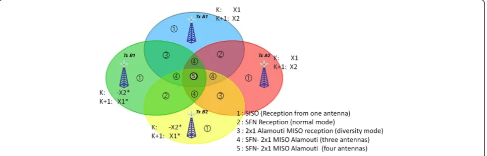
two adjacent orthogonal frequency division multiplexing (OFDM) carriers k and k + 1, respectively. The second transmission type is denoted mode “B” where the conju-gate symbols−a*m,l,p+ 1and a*m,l,pat the same carriersk and k+ 1, respectively. These symbols are transmitted as defined by Alamouti MISO based on two transmit anten-nas and a single receive antenna (2x1 Alamouti scheme) [11,17]. As specified by the standard DVB-T2 [4], indices m, l, and p are theT2-frame number, the symbol within the frame and the data cell within the symbol prior to frequency interleaving and pilot insertion, respectively. This proposed model allows the analysis of three transmission cases. The first one is the SFN (normal transmission) where transmitters transmit in mode “A”. The second is the 2x1 Alamouti MISO (diversity transmission) where one transmitter transmits in the mode “A” while the second transmits in the mode “B”. The third case is the SFN-2x1 Alamouti MISO based on three or four antennas where transmitters can transmit either in the mode “A” or “B”. This case is a combined transmission where we find one group of antennas which transmits the mode “A” and a second one which transmits the mode “B”. Each group forms an SFN network while the combination of these two groups forms a diversity transmission. Figure 1 illustrates our modeling approach. The different reception zones depending on the transmis-sion cases are detailed in this figure. Therefore, the reception areas from 1, 2, 3, and 4 antennas for these different reception zones are given.
The reception zones shown in Figure 1 are detailed as follows.
1) The zones labeled (1) is the reception zone from one antenna (transmission mode“A”or mode“B”) allowing normal transmissions.
2) The reception zone from two antennas and divided in two sub-cases allowing diversity transmissions:
i). The zones labeled (2) are the reception zones based on the 2x1AlamoutiMISO from two antennas (A1+B1orA2+B2).
ii). The zones labeled (3) correspond to reception zones based on an SFN network from two pair of antennas (A1+A2orB1+B2) and where each pair of antennas (A1+A2) and (B1+B2) refer to the mode“A”and“B”transmissions, respectively. 3) The zones labeled (4) refer to the reception zones
from three antennas (A1+A2+B1orA1+B1+B2) that represent the 2x1AlamoutiMISO in an SFN. These zones are considered as combined SFN-2x1 Alamouti MISO networks allowing diversity transmissions in an SFN network and according with the following configuration cases:
i). The antenna group (A1+A2) is considered as one antennaA12that corresponds to an SFN network in the mode“A”transmission while the antenna B1is in the mode“B”transmission. It results in a diversity transmission.
ii). Reciprocally, the antennaA1is in the mode“A” transmission while the antenna group (B1+B2) is considered as single antennaB12that corresponds to an SFN network. Similarly, this combined network allows a diversity transmission. 4) The zone (5) is the reception zone from four
antennas (A1+A2+B1+B2), which represent two combined SFN-2x1 Alamouti MISO allowing diversity transmission from the considered equivalent pair of antennas (A12+B12).
Three cases are studied in this work. In the first case, we have analyzed the reception signal from two antennas A1+ B1. In the second case, the reception signals from three antennasA1+A2+B1orA1+B1+B2were analyzed. Finally, the reception from four antennasA1+A2+B1+B2 were studied in the third case.
2.2. Model equations
To reconstruct the signal at each point in the reception zone in the case of 2x1 Alamouti MISO (diversity trans-mission), we formulate the reception for two transmitters by a single antenna at two different carrierskand k+ 1. The reconstruction of the transmitted signal is achieved from two received signalsy1andy2expressed by the vec-torYand specified by Equations (1) and (2), at the carriers kandk+ 1, respectively:
y1¼h1ðm;l;pÞ⋅aðm;l;pÞh2ðm;l;pÞ⋅aðm;l;pþ1Þþn1=2 ð1Þ
y2¼h1ðm;l;pþ1Þ⋅aðm;l;pþ1Þþh2ðm;l;pþ1Þ⋅aðm;l;pÞ
þn1=2 ð2Þ
wherey1andy2are the received signals at the sub-carriers
kand k+ 1.h1andh2are the coefficients of the channel defined by the matrix H between the two transmit
antennasA1andB1and the receiver. The component n1 is the complex random variable and represents the re-ceiver noise and interference defined by the vectorn.We can represent these equations in the following matrix form:
; is the data
transmis-sion vector.
For an SFN transmission model, more precisely 0 dB Echo, the received signal y(t) is computed as follows:
y tð Þ ¼h1⋅e tð Þ þh2⋅e tð τÞ ð4Þ
where h1 and h2 are the channel coefficients between the signale(t),e(t–τ), and the receiver. In the frequency domain, the received signal is given by the following expression:
y fð Þ ¼h1ðm;l;pÞ⋅E fð Þ þh3ðm;l;pÞ⋅e fð Þ⋅ej2πfτ ð5Þ
We deduce the received signals at the sub-carriers k andk+ 1 as follows:
We can represent these equations in the matrix form as defined by Equation (3) and where the matrix channel is given as follows:
H¼ ðjh1ðm;j;pjþjh3ðm;l;pÞj⋅ej2πfτÞ 0
0 h2ðm;j;pþ1Þþh4ðm;l;pþ1Þ⋅ej2πfτÞ
!
ð8Þ
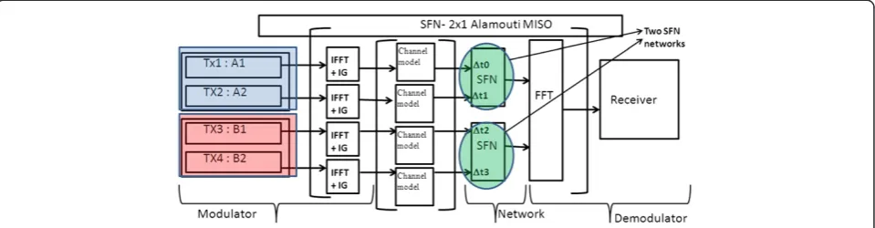
Our new proposal model is based on the superposition of an SFN with 2x1 Alamouti MISO in the case of four transmitters as depicted in Figure 2. As shown in this figure, the signals received from transmittersA1/A2and
B1/B2 are treated as pair of SFN combined in diversity transmission.
A1 + A2 + B1 + B2, we formulate the SFN-2x1
Alamouti MISO model by Equations (9) and (10), which are obtained at carrierskandk+ 1, respectively
y1¼h1ðm;l;pÞþh3ðm;l;pÞ⋅aðm;l;pÞ
h2ðm;l;pÞþh4ðm;l;pÞ⋅am;l;pþ1þn1=2 ð9Þ
y2¼h2ðm;l;pþ1Þþh4ðm;l;pþ1Þ⋅aðm;l;pÞ þh1ðm;l;pþ1Þþh3ðm;l;pþ1Þ⋅am;l;pþ1
þn1=2 ð10Þ
whereh3andh4are the coefficients of the channel between the two other transmittersA2andB2and the receiver. For simplification, we defineh1’andh2’as follows:
h10¼h1þh3 ð11Þ
h20¼h2þh4 ð12Þ
Note that in the case of three antennas h2’is equal to h2. Thus, the matrix H and Equations (9) and (10) at carrierskandk+ 1 can be written as follows:
H¼ h10ðm;l;pÞ h20ðm;l;pÞ
h20ðm;l;pþ1Þ h10ðm;l;pþ1Þ
ð13Þ
y1¼h01ðm;l;pÞ⋅aðm;l;pÞh20ðm;l;pÞ⋅am;l;pþ1þn1=2 ð14Þ
y2¼h02ðm;l;pþ1Þ⋅aðm;l;pÞþh01ðm;l;pþ1Þ⋅am;l;pþ1
þn1=2 ð15Þ
The DVB-T2 receiver makes measurements of the channel using pilots and then by interpolating between these measurements the estimates of the channel response for everyOFDMcell [4] are constructed. After estimating the channel, a Zero-Forcing equalizer for the signal model in Equation (3) provides the unbiased estimates
m,l,,p, m,l,p+1 [18] and is given by
¼ m;l;p
m;l;pþ1
¼ðH⋅HÞ1H⋅y
Note that the first term (H*∙ H–1) in Equation (16) corresponds to the equalization part whereas the term H* is the actual matched filter receiver for the vector signal model defined in Equation (3) [7]. By using the structure of the channel matrix inHthe entire matched filter matrix can be written as follows:
H⋅H
ð Þ1
H¼
h10ðm;l;pþ1Þ h20ðm;l;pÞ h20ðm;l;pþ1Þ h1ð0m;l;pÞ
h10ðm;l;pÞ⋅h10ðm;l;pþ1Þþh20ðm;l;pþ1Þ⋅h20ðm;l;pÞ ð17Þ
Consequently, the estimates  for the transmitted signal can be computed as follows:
âm;l;p¼ h1 0
m;l;pþ1
ð Þ⋅y1þh20ðm;l;pÞ⋅y2
h10ðm;l;pÞ⋅h10ðm;l;pþ1Þþh20ðm;l;pþ1Þh20ðm;l;pÞ
ð18Þ
âm;l;pþ1¼ h2 0
m;l;pþ1
ð Þ⋅y1þh10ðm;l;pÞ⋅y2
h10ðm;l;pÞ⋅h10ðm;l;pþ1Þþh20ðm;l;pþ1Þ⋅h20ðm;l;pÞ
ð19Þ
Note that for the flat fading case whereh1'(m,l,p)=h1'
(m,l,p+ 1)andh2'(m,l,p)=h2'(m,l,p+ 1), the resulting channel matrixHis orthogonal [7,17]. More precisely, the trans-mission model assumes that the channel does not vary during the two consecutive OFDM Symbols. Therefore, the resulting channel matrixHis orthogonal as explained by the following equation:
HH¼h
10ðm;l;pÞ⋅h1 0
m;l;p
ð Þ
þh2 0
m;l;p
ð Þ⋅h20ðm;l;pÞ 10 01
¼ h1 0
m;l;p
ð Þ
2
þ h2 0
m;l;p
ð Þ
2
⋅I; ð20Þ where the determinant of the Matrix H*H* is null (det (H*H*) = 0).Irepresents the identity Matrix.
For the frequency selective case where (h1'(m,l,p)≠h1' (m,l,p+ 1) and h2'(m,l,p)≠h2'(m,l,p+ 1)), the determinant of the MatrixH*H*is not null (det(H*∙H)=0). Consequently, the channel matrix H is no longer orthogonal and we deduce that the matched filter receiver no longer provides the optimum solution. Therefore, the above matched filter receiver converges towards the two following expressions solutions:
We have compared the performance of transmission in the case of SFN, 2x1 Alamouti MISO, and SFN-2x1Alamouti MISO (see Figure 1) for different types ofmodulationand code rate. The Alamouti 2x1 was chosen for the DVB-T2 standard because of its rate equals 1 (performance diversity gain without losing the throughput of transmission data). Indeed, the choice of another MISO type like 3x1 or 4x1 Tarokh can lead to lose some throughput of transmission data even if it has better diversity gain performance. More precisely, orthogonal codes based on three and four trans-mit antennas were proposed by Tarokh et al. [19]. The 3x1 and 4x1 Tarokh codes, when implemented as distributed orthogonal space–frequency block codes for diversity gain, have lower rates than for Alamouti [19-22], which leads to a loss in throughput for transmission. In addition, the main reason to use a 2x1 Alamouti rather than a 2 × 2 Alamouti is to avoid additional antennas at the receiver side as clearly specified in the new DVB-NGH standard [23].
The transmission model is defined for two, three, and four distributed antennas having the same received level power for different QAM modulation. The simulation of the DVB-T2 proposed model is achieved on the CSP DVB-T2 platform [24] based on theMatlabsoftware tool [25]. This platform validates the correct operation of the system starting from a digital stream at the DVB-T2 trans-mitter side and ending after its reconstruction at the receiver side passes through different types of channel (0-dB Echo, Rayleigh channel, Ricean channel).
We have considered the distributed scenario of the type 1 for the Alamouti MISO parameters with the following delay values (τi) of 0, 0.18Δ, 0.7Δ, and 0.9Δ. The parameter
Δ represents the guard interval fraction. These values represent an SFN (0.9Δ), Alamouti MISO (0.18Δ) (as defined in [4]), and two intermediate values in the case of three and four antennas. In this case study, we suppose
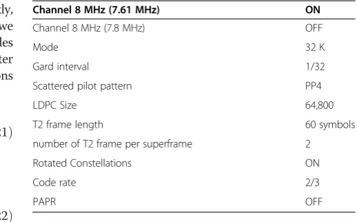
that there is no frequency offset. The parameters that are used in this simulation are shown in Table 1.
For this configuration, the bit rate values for SISO and Alamouti MISOfor256 QAM are 36.7722875 and 36.5777251 Mbits/s, respectively. The bit rate deviation (194.5624 kbits/s) corresponding to a carrier-to-noise ratio (C/N) deviation of 0.1 dB (by considering the Shannon capacity limit) does not cause a deviation in reception quality.
We model the reception from three antennas as follows: two antennas A1 andA2 model an SFN trans-mission. After the addition of antenna B1or B2, the system constitutes an SFN-2x1 Alamouti MISO transmis-sion (diversity transmistransmis-sion). The specific parameters simulation channel used are:
–For the antennasA1andA2the echo values (τIin μs) are 0 and 0.9 Δ, respectively, while the third antenna B1or B2 is equal to 0.18 Δ. We consider no frequency offset (Δfi= 0 Hz).
We model the reception based on four antennas from two pairs of antennas (A1, A2) and (B1, B2) representing an SFN network each one. The associ-ation of these pairs of antennas models a diversity transmission.
The parameter simulation of channel values of the mode transmission for this modeling is defined as follows.
–For the transmitters A1and A2the echo values (τIin
μs) are 0 and 0.9 Δ, respectively, while the antennas B1 and B2are equal to 0.18 Δ and 0.7 Δ, respectively. We consider no frequency offset (Δfi= 0 Hz).
It is important to study the channel frequency re-sponse in order to see the fading due to multipath for the delay values considered. The study of the channel characteristics for 2x1 Alamouti MISO, SFN, and SFN-2x1 Alamouti MISO transmissions are detailed as fol-lows. The SFN is modeled as a direct signale(t) and its signal echo e(t – τ). From Equations (4) and (5), the
Table 1 Configuration parameters for the proposed DVB-T2 modeling and simulation
Channel 8 MHz (7.61 MHz) ON
Channel 8 MHz (7.8 MHz) OFF
Mode 32 K
Gard interval 1/32
Scattered pilot pattern PP4
LDPC Size 64,800
T2 frame length 60 symbols
number of T2 frame per superframe 2
Rotated Constellations ON
Code rate 2/3
channel path gain can be expressed by the following equation:
R fð Þ E fð Þ
2¼2⋅ð1þ cos 2ð πfτÞÞ ð23Þ
The presence of similar-strength signals from two trans-mitters in a network causes a significant loss of margin. From Equation (23), we can deduce that the resulting channel can have deep “notches” corresponding to the frequency value of 1/2τ. The channel characteristics of 2x1 Alamouti MISO called equivalent channel can be expressed by the following equation:
H1ðm;l;pþ1Þ⋅H1ðm;l;pÞþH2ðm;l;pÞ⋅H2ðm;l;pþ1Þ
ð24Þ
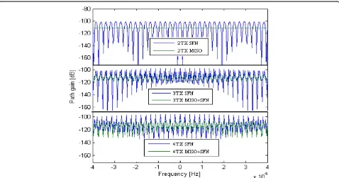
From these SFN and Alamouti MISO channel equa-tion models, we have simulated the path gain of the different reception case studies. More precisely, Figure 3 gives thepath gainsimulation results for pure SFN and SFN-2x1Alamouti MISO transmission from the recep-tion based on two, three, and four transmitters. These results show clearly that in the transmission based on two antennas, there are the deep “notches” for an SFN transmission, which leads transmission cuts. These results demonstrate that an Alamouti MISO transmis-sion allows to obtain better performance than an SFN transmission for two antennas. Thus, we can deduce that the diversity transmission based on two antennas elimi-nates the notches produced in an SFN network and
improves the diversity gain. To justify the reliability of our MISO simulation and verify the functionality of the platform with the considered Alamouti MISO configu-ration, the reference used to validate our simulation results is based on the comparison of the BER results of the MISO two antennas transmission and the Gaussian channel transmission. Indeed, theoretically the Fourier transform of the Gaussian channel is almost the same that of the MISO two antennas transmission, which eliminates thenotchesthat exist in pure SFN 0-dB Echo transmission. In the case of three transmitters, the simulation results show that the performance of thepath gainof the SFN-2x1 Alamouti MISO transmission is still better than that of an SFN transmission although the“notches”for both transmis-sion cases still remain though only the deep “notches” for the SFN transmission. Thereby, we can deduce that the diversity reduces the notches compared to SFN network based on three antennas. In the case of four antennas, both transmissions mode have a badpath gainand are charac-terized by the deep“notches”. Consequently, for four trans-mitters, the impact of diversity compared to normal transmission (pure SFN) is negligible. From these different case studies, we can note that the efficiency of the SFN-2x1 Alamouti MISO transmission decreases as the number of antennas at the transmission side increases.
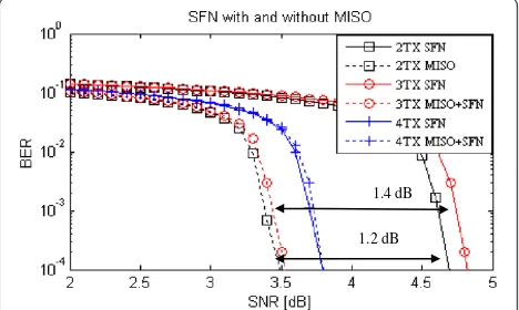
Figures 4, 5, 6, and 7 compare the BER performance between the SFN with and without 2x1AlamoutiMISO. These simulation results use the configuration parameters as specified in Table 1 and for different types of
modulations (QPSK, 16 QAM, 64 QAM, and 256 QAM). Indeed, the QEF (quasi-error free) condition of the pro-posed DVB-T2 configuration is achieved when BER is equal to 10–4with a LDPC decoding, which corresponds to a BER of approximately 10–7after a BCH decoding [4]. From these results and in the case of two or three anten-nas, we observe that whatever the modulation types, an Alamouti MISO transmission (two antennas) or an SFN -2x1 Alamouti MISO transmission (three antennas) are more efficient. In an SFN transmission for two or three an-tennas, the presence of similar-strength signals from the transmitters in a network causes a significantloss of margin because the resulting channel can have deep “notches”. Thesenotchesare removed by the two antennas (due to the diversity transmission) and their effect are reduced for three antennas with a diversity 2x1 Alamouti MISO transmission (see Figure 3). Thus, thepath gainfor an Alamouti MISO transmission is better than the path gain of a pure SFN transmission. However, in the cases of four antennas, we have observed that the BER measurement for an SFN transmission has almost the same performance as an SFN with Alamouti MISO transmission. More precisely, there is no impact of the diversity transmission compared to
normal transmission for this case studied. This perform-ance is due to the path gain for an SFN-2x1 Alamouti MISO,which is not better than in a classical SFN transmis-sion (see Figure 3). In addition to the similarity in thepath gain, the matched filter receiver no longer provides the optimum solution because the matrix His no longer or-thogonal. Finally, these simulations results show also that in the case of three antennas the gain provided by Alamouti MISO is about 1.4 dB for all types of modulation. In the case of two antennas, the gain is increased with an increas-ing constellation size. Thus,AlamoutiMISO improves the gain of 1.2, 1.6, 2, and 2.5 dBs for QPSK, 16 QAM, 64 QAM, and 256 QAM modulations, respectively. Therefore, we can deduce that there is no gain in the case of an SFN -2x1 Alamouti MISO transmission based on four antennas. For four antennas, there is no gain with an SFN-2x1 MISO Alamouti compared to normal SFN broadcast network. The main explanation is due to the attenuation of two SFN networks caused by the notches of each one. Indeed, these notches are not corrected unlike in the case of two and three antennas where the notches are corrected by the third diversity antenna. As constellation order gets higher, bits 1.4 dB
2.5 dB
Figure 4BER performance results for the configuration 256 QAM, 2/3, 32 k, 0-dB ECHO, PP4.
2 dB 1.4 dB
Figure 5BER performance results for the configuration 64 QAM, 2/3, 32 k, 0-dB ECHO, PP4.
1.6 dB 1.3 dB
Figure 6BER performance results for the configuration 16 QAM, 2/3, 32 k, 0-dB ECHO, PP4.
1.2 dB 1.4 dB
per constellation are higher and the distance between the constellations is closer, which makes it more sensitive for the channel fading and noise. Consequently, the reception performance is better as constellation order gets lower at the expense of the less data rate for pure SFN network or SFN-2x1 Alamouti MISO. Compared to pure SFN network, the better gain of SFN-2x1 Alamouti MISO obtained with a higher constellation order is because for a higher constellation order the received performance is more sensitive to the channel fading and noise. Therefore, for the same channel fading, the 2x1 Alamouti MISO diver-sity corrects more errors compared to lower orders and achieves a better diversity gain. Consequently, these results allow the broadcasters to define an efficient network com-bination (classical SFN or combined SFN with Alamouti MISO networks) before planning their network forms.
Possible extensions to mobile scenarios are also envi-sioned for the DVB-T2 [4]. However, actually there are not any performance evaluations of the TU6 in an SFN network with distributed 2x1 Alamouti MISO for DVB-T2. For example, in mobility conditions the Inter Carrier Interferencedue toDopplerspreading can produce a different impact on the BER performance. Therefore, it is interesting to study the BER performance for different case studies. Consequently, we have also studied and evaluated the performance of a classical SFN network compared to SFN with distributedAlamoutiMISO coding overDoppler mobile channel.
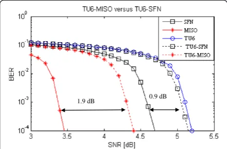
3. Model and evaluation performance of SFN TU6 and MISO TU6
TU6 channel profile reproduces the terrestrial propaga-tion in an urban area. It has been defined by COST 207 as a typical urban (TU6) profile and is made of six paths having a wide dispersion in delay and relatively strong power. We have measured the performance of DVB-T2 for two transmitters/one receiver system communication in aTU6, SFN and Alamouti MISO channel models on the one hand and combined TU6-MISO, TU6-SFN,and on the other hand. We have considered the mobility (TU6 model) forDopplerfrequency 80 Hz for the DVB-T2. We have supposed that the receiver receives the same power from the two transmit antennas.
In our case study, for modeling an SFN network over TU6 channel, we have considered a classical SFN network of two transmit antennas for a delay of 0.9Δ with independent TU6 channel on each link [4]. We considered two distributed transmit antennas using Alamouti coding and a single receive antenna with inde-pendentTU6channel on each link for model an Alamouti MISO transmission over TU6 channel.
We describe the BER performance as a function ofC/N obtained for DVB-T2 simulations. The parameters used for these simulations are similar to those for Table 1
except for the Mode, Guard Interval, and the Scattered pilot pattern, which are 8 K, 1/8, and PP2, respectively. The examined constellation isQPSKand the code rate is 2/3. The QEFcondition is assumed to be achieved when BER is equal to 10–7after LDPC decoding and 10–11after a BCH decoder. TheDoppler frequencyused is equivalent to 118 km/h for a carrier frequency of 730 MHz and a data rate corresponding to 7.8 Mbit/s. Therefore, we have adopted a small bit rate allowing robust receivers.
Figure 8 shows the numerical results of these simula-tions. Comparing the SFN and the SFN with Alamouti MISO, we can deduce that an SFN-2x1 Alamouti MISO transmission yields better performance than classical SFN transmission. This result explains the gain of diversity compared to normal transmission. Indeed, the simulation obtained results show a degradation of the performance of BER usingTU6model. This degradation is less if theTU6 model is used in the classical SFN network. This degrad-ation can be solved by using TU6model with Alamouti MISO decoding. The obtained results show clearly that the BER performance using TU6 model with MISO decoding is better than that of a classical SFN network for two transmit antennas. Thus, one can minimize the degradation ofTU6for DVB-T2.
4. Performance evaluation with unbalanced received power
To evaluate the unbalance received power signals at the receiver, which represent the attenuation of some transmit-ters compared to others, we have simulated different values of attenuated echo for SFN and SFN-2x1 Alamouti MISO transmissions. We have studied the performance evalua-tions of SNR over different levels of received power. Thus, we have considered three cases for this simulation. The first case represents the received power from two antennas transmitting two signals corresponding at one direct and one variable power level echo of 0.9Δ. Table 2 presents the
1.9 dB 0.9 dB
SNR results for the SFN and Alamouti MISO networks for two and three antennas.
We have deduced that the SNR value for two antennas decreases when the attenuation level of the echo signal increases. Then, it reaches a Ricean channel performance value when the attenuated value increases further. However, for the Alamouti MISO transmission technique-based net-work, the SNR value remains stable. This can be explained by the Fourier transform of the channel of SFN-2x1 Alamouti MISO network represented in Figure 3 where it can be seen that the 2x1 Alamouti MISO equivalent chan-nel is constant. However, for an SFN the notches will be recovered and reduced by the attenuated power level of the echo. Thus, this will give better SNR performance.
The second case study represents the received signals from three antennas transmitting three signals correspond-ing at one direct and two variable power level echo of 0.18Δ and 0.9Δ, respectively. The direct and echo 0.9Δ signals transmit the same symbols (modeA) while the echo 0.18Δsignal transmits conjugate symbols (modeB). Again, we can deduce that in the case of an SFN-2x1 Alamouti MISO, the SNR is almost constant when the echo 0.18Δis attenuated. These results can be explained as if we have an Alamouti MISO of two transmitters. The first one is the combined signal pair of direct and echo 0.9Δ while the second is the echo 0.18Δ,which becomes similar to the first case. However, if the second echo (0.9Δ)is attenuated the SNR values tend towards those of an 2x1 Alamouti MISO technique network based on two antennas.
The third studied case is concerned with the received power level from four antennas transmitting four signals corresponding to one direct signal and three echo signals of 0.18Δ, 0.72Δ, and 0.9Δ, respectively. The direct and echo 0.9Δsignalstransmit the same symbols while the echo sig-nals of 0.72Δand 0.18Δtransmit the conjugate symbols.
Table 3 lists the SNR evaluations obtained. These results show that if we attenuate one of the four anten-nas, an SFN-2x1 Alamouti MISO network tends to work as an SFN-2x1 Alamouti MISO based on three antennas only (second case studied).
More precisely, this case has the same evaluation result as an SFN-2x1 Alamouti MISO network based on three antennas. If we attenuate two antennas (antenna 2 or 3 and antenna 4 at the same time) corresponding to two pairs of antennas modeling two SFN networks (the first one is the combined signal pair of direct and echo 0.9Δ while the second is the combined of echo 0.18Δ and0.72Δ), then these two networks form an SFN-2x1 Alamouti MISO. The SNR value depends on the ated echo of each pair of SFN. In addition, if we attenu-ate two antennas transmitting the same symbols (for
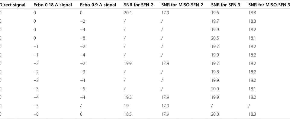
Table 2 Unbalanced received power level results for two, three antennas (in dB)
Direct signal Echo 0.18Δsignal Echo 0.9Δsignal SNR for SFN 2 SNR for MISO-SFN 2 SNR for SFN 3 SNR for MISO-SFN 3
0 0 0 20.4 17.9 19.6 18.3
0 0 −2 / / 19.7 18.3
0 0 −4 / / 19.9 18.2
0 0 −8 / / 20.5 18.1
0 −1 −2 / / 19.7 18.2
0 −1 −4 / / 19.9 18.2
0 −2 −2 19.9 17.9 19.7 18.2
0 −2 −3 / / 19.8 18.2
0 −2 −4 / / 19.9 18.2
0 −3 −5 / / 20.0 18.1
0 −4 −4 19.3 17.9 19.9 18.2
0 −5 / 19 17.9 / /
0 −8 0 18.5 17.9 20.0 18.3
Table 3 Unbalanced received power level results for four antennas (in dB)
Direct signal
Echo 0.18
Δsignal
Echo 0.72
Δsignal
Echo 0.9
Δsignal SNR for SFN
SNR for MISO-SFN
0 0 0 0 18.8 18.9
0 0 0 −2 18.9 18.8
0 0 0 −5 19.2 18.6
0 0 0 −8 19.4 18.5
0 0 −5 0 19.1 18.6
0 0 −2 −5 19.2 18.6
0 0 −10 0 19.3 18.4
0 0 −8 −8 19.2 18.2
0 −2 −5 −5 19.1 18.6
0 −5 −5 −5 19.1 18.6
instance antenna 2 and 3 or antennas 1 and 4 at the same time), the resulting SNR tends to be stable at 18.9 dB and behaves as an SFN-2x1 Alamouti MISO network with two antennas. Indeed, this case represents two pair of SFN networks that undergoes a diversity transmission signals. One of these two SFN networks is attenuated and refers to the case of an attenuated echo for MISO based on two transmitters. However, if three echo signals are attenuated, the network behavior depends on the attenuation levels while the value of SNR depends on the attenuated echoes.
5. Performance evaluation with rotated constellations
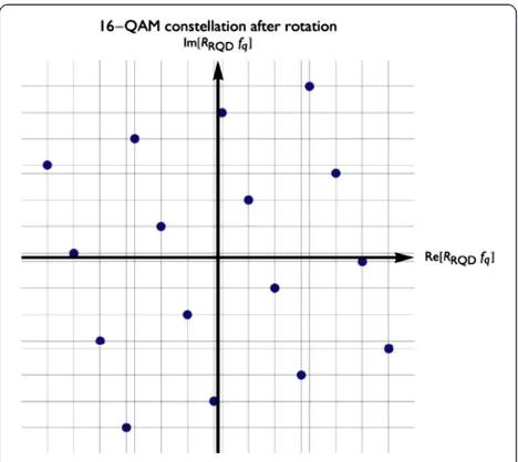
The rotated constellations, which provide a form of modulation diversity, are useful to assist in the reception of higher-code-rate signals in demanding transmission channels [26,27]. The technique of rotated constellations proposed by the DVB-T2 standard consists of applying a rotation to the QAM constellation followed by a component-axes interleaving. The DVB-T2 is not limited by the use of the obtained full rank transmission matrices. Indeed, it is the interleaving with constellation rotation which improves the diversity performance. The principles use of rotated constellation is as follows [28]. In a non-rotated constellation, the receiver needs both in phase (I) and quadrature (Q) components of one constellation point to identify what information was transmitted, because the estimation of I does not give information about Q compo-nent. Besides, both components suffer the same fading when the signal is propagated over the channel. In the case of a rotated constellation, a certain rotation angle is applied in the complex plane to a classical signal constellation, such that each component, I or Q, has enough information by its own to estimate what transmitted symbol was. After the rotation, an interleaving process is performed only over the Q components [28]. This is done in order to transmit separately the I and Q of a constellation point in different carriers and even in different time slots. Thus, if one of the components is destroyed or affected by a deep selective fading of the channel, the other component can be used to recover the information. In addition, due to this interlea-ving process, the in-phase and quadrature components of a transmitted symbol are affected by independent fading. The result of this technique is to increase the robustness of the receiver in propagation scenarios with deep fades and/or erasure events. Therefore, after rotating, the projections of the constellation points on the I and Q channels carry the information regarding themmapped bits. For a 16-QAM, instead of 2m/2= 4 projections on each axis, the constella-tion now has 2m= 16 projections as seen in Figure 9 [4].
Thereby, the insertion of the interleaving between I and Q leads to the same information being sent twice over the channel in different cells, as if an inner
repetition code was used. The resulting“virtual” constel-lation after rotation and cyclic delay in the case of a 16-QAM is shown in Figure 10 [4].
It is equivalent to sending a higher-order irregular QAM while having the spectral efficiency of the original QAM. This leads to additional diversity that improves the error-correcting performance when severely faded channels are encountered [4]. The component-axes (or I/Q) inter-leaving is performed by using a cyclic delay before cell-interleavers and time-cell-interleavers. The optimum choice of the angle is dependent on modulation order, channel type,
Figure 916-QAM constellation after rotation.
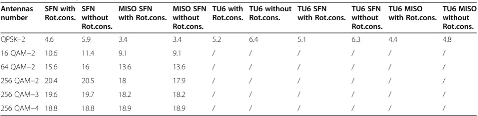
and mapping type. For each modulation order (constella-tion size), a single corresponding rota(constella-tion has been chosen. In this section, we study the performance of rotated constellations for the previous different configurations used. More precisely, we will study the performance of rotated constellation for SFN-2x1 Alamouti MISO network with the configuration specified in Table 1 and TU6 channel with the configuration specified in Section 3. The results are shown in Table 4. This table gives the results of the SNR performance for different types of networks (SFN, SFN-2x1 Alamouti MISO) with and without rotated con-stellations over different numbers of antennas, and different types of constellations. Therefore, for instance in this table, the 256 QAM−2 means that the number of antennas is two and the constellation is 256 QAM. Note that the gain obtained by using a rotated constellationalso depends on the receiver implementation. The worst case theoretically for the simplest implementation is supposed to obtain the same performance whether the rotated constellation can be used or not. These results show that for diversity transmis-sions, the values of SNR are almost stable with and without rotated constellations for all cases except for the TU6-MISO case where a deviation of 0.4 dB was obtained. For the pure SFN network case, the values of SNR depend on the type of modulation. For the 256 QAM modulations, the values are almost stable for rotated constellations in active and no-active modes. However, for others modulations (64 QAM, 16 QAM, QPSK) the deviation increases when bits per constellation decreases. For QPSK, the highest deviation was obtained.
6. Conclusion
This article addresses a new model including the simulation results and gives a detailed analysis of the performance of theAlamouticode in an SFN for DVB-T2 for two, three, and four transmitters, different types of coding, and modu-lations. We have studied and evaluated the expected performance for the transmission-based Alamouti MISO technique, which is an option in the DVB-T2 standard. Our proposed model has been implemented in the CSPDVB-T2
platform. To achieve this, we have proposed a new model DVB-T2 configuration to simulate an SFN network transmission with Alamouti MISO in order to improve the quality of the received signals. The simulation results obtained show clearly that in the case of two, three, or four transmission antennas, the performance of SFN (0-dB Echo profile) with Distributed Alamouti MISO is only better than that of a classical SFN for two and three antennas. However, in the case of four antennas, the results obtained show clearly that a classical SFN transmis-sion has almost the same performance as an SFN with Alamouti MISO. These simulation results show also that in the case of three antennas the gain provided by Alamouti MISO is bigger than 1.5 dB for all types of modulation. In the case of two antennas, the gain is increased with bits per constellation. Consequently, Alamouti MISO improves the gain by 1.2, 1.6, 2, and 2.5 dB for QPSK, 16 QAM, 64 QAM, and 256 QAM modulations, respectively. Finally, we deduce that there is no gain only for the case of an SFN with Alamouti MISO transmission based on four antennas.
We conclude that the reception performance obtained with an SFN-2x1 Alamouti MISO is better than a pure SFN network when constellation order gets lower. Indeed, for the same channel fading, the 2x1 Alamouti MISO diver-sity corrects more errors when compared to lower orders and, then, achieves a better diversity gain.
We have also shown that the unbalanced received power has no effect for Alamouti MISO transmission (MISO two antennas). However, some effects appear for the SFN and SFN-2x1 Alamouti MISO networks. More precisely, we have demonstrated that SFN or SFN-2x1 Alamouti MISO networks based on four antennas behave like a three-antenna SFN or SFN-2x1 Alamouti MISO networks, or three antennas SFN or SFN-2x1 Alamouti MISO networks operate like a two-antenna SFN or SFN-2x1 Alamouti MISO networks depending on the echo attenuation. In the case of the rotated constellation study, only the SFN network undergoes the effects when the deviation between the rotated constellations is active depending on the modu-lation type. Thus, we show that the expected results
Table 4 Rotated constellation effects in term of SNR contributions for the used MISO-SFN configuration, TU6-MISO, and TU6-SFN configurations (in dB)
demonstrate that broadcasters who consider that Alamouti MISO always give a performance better than SFN are not always correct. These results are very important for the broadcaster who will set the operational management plan-ning and the network deployment. Indeed, depending on whether an SFN-2x1 Alamouti MISO transmission gives better performance than a classical SFN trans-mission, or not, the broadcaster defines the appropriate transmission network.
The results obtained also suggest that the BER performance using TU6 model with Alamouti MISO decoding performs better than when using a classical SFN network with two transmitting antennas. This allows us to minimize the degradations of TU6 for DVB-T2. The results converge as expected with the comparison between a classical SFN and an SFN-2x1 Alamouti MISO. This trend will need to be investigated in more detail as future work. Other future work will be to study and evaluate the BER performance for the same channel models when using other Doppler frequencies in a network of more than two antennas.
Competing interests
The authors declare that they have no competing interests.
Author details 1
Interfaces, Sensors and Microelectronics laboratory (LICM), University of Lorraine at Metz, 7 rue Marconi, 57070, Metz, France.2Télédiffusion de France
(TDF), 1 rue Marconi, 57070, Metz, France.
Received: 20 June 2011 Accepted: 4 February 2013 Published: 19 March 2013
References
1. ETSI EN 300 744 V1.6.1, Digital Video Broadcasting (DVB),Framing structure, channel coding and modulation for digital terrestrial television, European Standard Telecommunications series, European Broadcasting Union(ETSI, 2009) 2. ETSI TR 101 190 V1.3.1, Digital Video Broadcasting (DVB),Implementation
guidelines for DVB terrestrial services; Transmission aspects, European Standard Telecommunications series, European Broadcasting Union(ETSI, 2008) 3. ETSI TS 101 191 V1.4.1, Digital Video Broadcasting (DVB),DVB mega-frame
for Single Frequency Network (SFN) synchronization, European Standard Telecommunications series, European Broadcasting Union(ETSI, 2004) 4. ETSI TR 102 831 V<0.8.57>Digital Video Broadcasting (DVB),Implementation
guidelines for a second generation digital terrestrial television broadcasting system (DVB-T2, European Standard Telecommunications series, European Broadcasting Union)(ETSI, 2008)
5. H Bölcskei, AJ Paulraj, Space-frequency coded broadband OFDM systems. inProceedings of the IEEE Wireless Communication Network Conference (WCNC)1, 16 (2000)
6. J Yang, K Cheun, Low complexity implementation of Alamouti space-time coded OFDM transmitters. IEEE Commun Lett8(4), 229–231 (2004) 7. A Hutter, S Mekrazi, BN Getu, F Platbrood, Alamouti-based space-frequency
coding for OFDM. Int. J. Wirel. Personal Commun.35(1–2), 173–185 (2005) 8. W Su, Z Safar, KJR Liu, Full-rate full-diversity space-frequency codes with
optimum coding advantage. IEEE Trans Inf Theory51(1), 229–249 (2005) 9. K Lee, D Williams, A space-frequency transmitter diversity technique for
OFDM systems. inProceedings of IEEE GLOBECOM3, 14731477 (2000) 10. ETSI EN 302 755 V1.1.1, Digital Video Broadcasting (DVB),Frame structure
channel coding and modulation for a second generation digital terrestrial television broadcasting system (DVB-T2)(ETSI, 2009)
11. SM Alamouti, A simple transmit diversity technique for wireless communications. IEEE J. Sel. Areas Commun.16(8), 1451–1458 (1998)
12. M Poggioni, L Rugini, P Banelli, DVB-T/H and T-DMB: Physical layer performance comparison in fast mobile channels. IEEE Trans Broadcast 55(4), 719–730 (2009)
13. S Ruiz-Boqué, C Lopez, C Enrique, L Alonso, J Olmos, M Garcia, F Minerva,
Performance of DVB-T2 improvements over low Doppler mobile channels, European Cooperation in the field of scientific and technical research, COST 2100 TD(08) 451(Wroclaw, Poland, 2008)
14. L Kondrad, VKM Vadakital, I Bouazizi, M Gabbouj, Cross layer optimization of DVB-T2 system for mobile services. Hindawi J. Dig. Multimed. Broadcast 2010, Article ID 435405 (2010)
15. A Vigato, S Tomasin, L Vangelista, V Mignone, N Benvenuto, A Morello, Coded decision directed demodulation for second generation digital video broadcasting standard. IEEE Trans Broadcast55(3), 607–615 (2009) 16. M Anders, Single frequency network in DTV. IEEE Trans Broadcast51(4),
1432–1436 (2005)
17. B Badic, M Rupp, H Weinrichter, Adaptive channel matched extended Alamouti space-time code exploiting partial feedback. ETRI J26(5), 443451 (2004) 18. MR McKay, IB Collings, Capacity and performance of MIMO-BICM with
zero-forcing receivers. IEEE Trans Commun53(1), 74–83 (2005) 19. V Tarokh, H Jafarkhani, A Calderbank, Space-time block codes from
orthogonal designs. IEEE Trans Inf Theory45, 1456–1467 (1999) 20. V Tarokh, H Jafarkhani Et, AR Calderbank, Space-time block coding for
wireless communications: performance results. IEEE J. Sel. Areas Commun. Inf. Theory17, 451–460 (1999)
21. V Tarokh, N Seshadri, A Calderbank, Space-time codes for high data rate wireless communication: performance criterion and code construction. IEEE Trans Inf Theory44, 744–765 (1998)
22. M Tormos, C Tanougast, A Dandache, P Bretillon, P Kasser, Performance evaluation of distributed Tarokh SFBC and Alamouti MISO for SFN DVB-T2 broadcast networks, ininProceedings of the IEEE International Conference on Electronics, Circuits and Systems, IEEE Circuits and Systems Society, 2011, p. 583586 23. DVB NGH, TM-H NGH Study mission report, Standard Telecommunications
series, European Broadcasting Union, 2008, p. TM 4026r1
24. O Haffenden,DVB-T2: The common simulation platform, Research white paper, British Broadcasting Corporation(2011), p. WHP 196
25. Mathworks, Matlab Software, Version 7.8.0 (R2009a), The Mathworks Inc.
(Massachusetts (USA), 2009)
26. C Abdel Nour, C Douillard,Rotated QAM constellation to improve BICM performance for DVB-T2, inProceedings of the International Symposium on Spread Spectrum Techniques and Applications (ISSSTA 2008)(Bologna (Italy), 2008), pp. 354–359. Patent no FR 2927754, 02
27. M Tormos, C Tanougast, P Bretillon, P Kasser, A Dandache, "Experimental performance of mobile DVB-T2 in SFN and distributed MISO Network", in
Proceedings of the IEEE International Conference on Telecommunications (ICT 2012)(Jounieh (Labanon), 2012), pp. 1–5
28. D Perez-Calderón, C Oria, J García, P López, V Baena, I Lacadena, Rotated constellations for DVB-T2, inProceedings of the Design of Circuits and Integrated Systems Conference (DCIS 2009)(Zaragoza (Spain), 2009), pp. 41–45
doi:10.1186/1687-1499-2013-78
Cite this article as:Tormoset al.:Modeling and performance evaluations ofAlamoutitechnique in a single frequency network forDVB-T2. EURASIP Journal on Wireless Communications and Networking20132013:78.
Submit your manuscript to a
journal and benefi t from:
7Convenient online submission 7Rigorous peer review
7Immediate publication on acceptance 7Open access: articles freely available online 7High visibility within the fi eld
7Retaining the copyright to your article