R E S E A R C H
Open Access
Energy efficiency optimization-oriented
control plane and user plane adaptation
with a frameless network architecture for 5G
Xiaodong Xu
1*, Xun Dai
1, Ya Liu
2, Rui Gao
3and Xiaofeng Tao
1Abstract
In order to fully explore the merits of the multi-tier heterogeneous network (HetNet) and ultra-dense small cell deployments, the evolution of the cellular network architecture is on the way. Based on the frameless network architecture, this paper proposes the control plane (CP) and user plane (UP) adaptation strategy to improve the system energy efficiency (EE). In this paper, we give a three-step system EE optimization with constraints on the CP/UP adaptation. We optimize the system EE via CP and UP construction and adaptation while guaranteeing the user quality of service (QoS). In the first step, the CP construction and adaptation scheme is proposed through the Voronoi Diagram with EE improvements. In the second step, by jointly allocating the AE and subchannel resources, we construct the on-demand user-centric UP. In the last step, based on the UP construction from the second step, we adjust each UP to optimize the EE performance. This is achieved by employing game theory. Furthermore, we verify the existence and uniqueness of the Nash Equilibrium for the non-cooperative game model with pricing. Finally, the system-level simulation results show that, with constraints on the QoS of the users, the system EE performances are improved.
Keywords:CP and UP adaptation; Frameless network architecture; Energy efficiency; Joint resource allocation; Power adjustment; Genetic algorithm; Game theory; Nash Equilibrium
1 Introduction
Currently, the mobile Internet applications and versatile mobile services are affecting every aspect of our daily life. Specifically, the dramatic increase of the data traffic poses great challenge to the network capacity and forces the mobile operators to make revolutionary changes. Besides expanding the spectrum and improving the radio transmission, the mobile network architecture is considered as another potential way of further increas-ing the capacity of the 5th generation mobile systems (5G) [1, 2].
Heterogeneous network (HetNet) was proposed to meet the future demand by deploying multiple types of base stations (BSs) into the existing networks [3]. In addition, the small cell network (SCN) was introduced into the standard framework of the 3rd Generation
Partnership Project (3GPP) to increase hot-spot capacity [4]. Considering the coordinated multi-point transmission/ reception (CoMP) and relay techniques [5], the future mobile radio access network (RAN) architecture will have many distinct features comparing to current net-works, such as:
Small cell-based ultra-dense cellular deployments;
Multi-tier heterogeneous network supporting;
More BSs than users;
Coordination among different types of BSs;
Dense and irregular cellular network topology;
Separation of the control plane (CP) and user plane
(UP);
Flexible cell association and dual connectivity for users.
With all these new features of the HetNet, the RAN architecture has to evolve dramatically. There are many aspects needed to be researched in the future, such as * Correspondence:[email protected]
1
National Engineering Laboratory for Mobile Network Security, Beijing University of Posts and Telecommunications, Beijing 100876, China Full list of author information is available at the end of the article
the cellular network modeling with dense and irregular deployments, the influence of separated CP&UP on sys-tem energy efficiency (EE), and so on.
Currently, there is significant research on the C-RAN, Open RAN, Soft Cell, and frameless network architec-ture (FNA) [6–10]. Based on the baseband pool, China Mobile Research Institute proposed C-RAN featuring a centralized base band unit, coordination, and cloud computing [6]. A software-defined RAN architecture is implemented through the virtualization in [7]. For the Soft Cell concept proposed in [8], the transparent sets of BSs are provided for users.
Research on the FNA has also been studied substantially. In [9, 10], the concept of the FNA was given to explore the capacity gain in the network architecture evolution. Several important metrics, e.g., the user-centric frameless coverage definition with coordinated serving set construction, centralized resource management, CP/UP separation and adaptation, were considered and found to support the FNA networking. In the FNA, the resource pooling and service slicing schemes are proposed for different user quality of service (QoS) guaranteed resource allo-cations. According to the booming and strong re-search conducted in this field, FNA is a promising solution for fulfilling the requirements of 5G. Specific-ally, the user-centric service and cloud computing fea-tures are important for managing the multi-tier HetNets.
The research topics for the FNA include the network topology modeling, on-demand user-centric serving set construction, CP/UP adaptation, mobility management, and so on. In this paper, we focus on the CP/UP adapta-tion schemes based on the FNA.
In mobile networks, 3GPP has already started dis-cussions on the CP/UP separation. The RAN2 Study Item - Small Cell Enhancement studies the dual con-nectivity in the small cell scenarios. It allows users to connect to both small cells and macrocells at the same time, which can effectively reduce the frequency of handovers. Therefore, CP and UP are separated to achieve high efficiency, flexibility, and low cost. Furthermore, 3GPP has designed two alternative architectures for the CP and nine alternative architectures for the UP. In this scheme, the CP/UP may both be maintained coopera-tively by the macro- and small cells.
However, the separation of the CP and UP introduces new relationship between their coverage areas, which could be modeled by constraints on the deployment of CP and UP. Considering the constraints, the system EE could be further improved by dynamically adjusting the separated CP and UP. This method is defined as the CP/ UP adaptation. The CP/UP adaptation also raises challenges for the AE association on the aforementioned user connectivity, such as choosing the“best”AE for the
specific user considering both the user QoS requirement and the system EE.
In this paper, we present the constraints and adapta-tion scheme for the CP and UP separaadapta-tion. A three-step optimization solution is given. The main contributions of this paper are highlighted as follows:
CP/UP separation-based adaptation model is
constructed with constraints.
The CP construction and adaptation scheme is given
using the Voronoi Diagram with EE optimization.
Considering the user QoS requirements, on-demand
user-centric UP construction with joint resource allocation (AE and subchannel) for establishing the serving set is studied. Equal power allocation for all the UPs are maintained by the AEs within the serving set. The coordination between the AEs is implemented for better supporting different user QoS requirements.
Game theory is employed for power adjustment
based UP adaptation to achieve the optimal EE performance. Additionally, we also verified the existence and uniqueness of the Nash Equilibrium for the proposed non-cooperative game model.
The structure of this paper is arranged as follows. In Section 2, we give the system model for the FNA and put constraints on the CP/UP. In Section 3, we propose a Voronoi Diagram-based CP construction and adapta-tion for EE optimizaadapta-tion. Then, we study the joint allo-cation of the AE and subchannels for UP construction in Section 4 and game theory-based power adjustment for UP adaptation in Section 5. Finally, we give the EE performance evaluation and simulation of CP/UP adap-tation in Section 6.
2 FNA deployment scenario for the CP/UP adaptation
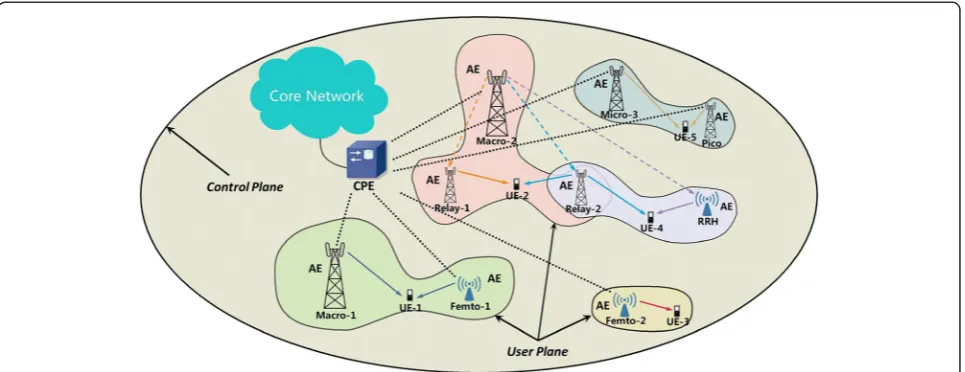
The target of FNA is to give a set of principles to guide the development of user-centric network architecture for the 5G. The typical deployment scenario of FNA is shown as in Fig. 1 with the core network (CN), RAN deployments, and user equipment (UE).
responsible for the radio signals’transmission/reception. The backhaul links between the CPE and AE could be the fiber, wireless backhaul, wired connections, and so on. The capacity and latency abilities for different back-haul links are different, which also pose challenges to resource allocations. The backhaul issues will be focused on for future researches.
The AEs are selected to construct a serving set for the specific user according to its QoS requirement. The serving set may contain one or several AEs. The AE can be equipped with a single antenna or an antenna array. According to different transmission power limitations, the AEs are classified into several types that have differ-ent coverage abilities, such as the Macro AE, Micro AE, Pico AE, Femto AE, RRH AE, and etc. Each AE has its own limitations of resource usage and power constraints. The AEs in the serving set can be of different types, which provide more flexible serving set constructions.
Based on the FNA, each user is always focused as being the coverage center of the serving AE set, which means the cell boundary or the traditional cellular structure will no longer exist. The user does not need to handover while moving through the network. Specific-ally, a user’s serving set will be updated adaptively to fulfill its QoS requirement and ensure the user is al-ways staying at the coverage center. Such mechanism provides a typical on-demand user-centric environ-ment with FNA.
Therefore, the AE is actually a new dimension of radio resource, which can be dynamically allocated and sched-uled by CPE. Each AE could be viewed as a type of coverage resource with different transmission power constraints. As shown in Fig. 1, Macro AE, Pico AE, Femto AE, Relay AE, and RRH AE are deployed as underlay. The UE-1 is served with a coordinated
transmission mode with AEs Macro-1 and Femto-1 as the serving set with UE-1 QoS requirement. The UE-2 is served by AEs Macro-2, Relay-1, and Relay-2. The Femto-2 serves the UE-3 as the only corresponding AE. The AE Relay-2 in the serving set for UE-4 is the com-mon node for the serving set of the UE-2. For the UE-5, the AEs Micro-3 and Pico AE make up its serving set. The coordinated transmission scheme can be a joint processing scheme based on CoMP or an enhanced coordinated transmission scheme with pre-coding tech-niques. The coverage area for the serving set of each UE will be amorphous due to the adaptive serving set constructing and updating.
In FNA, the resource pooling scheme is proposed to manage the multi-dimensional resources in a centralized manner. Multi-dimensional resource management is processed in the CPE with different optimization goals for different deployment scenarios. A uniform resource allocation strategy can take full advantage of centralized optimization that can improve the resource and energy efficiency, where [9] have already provided some results.
The power limitation of the AE is always the main con-straint for the RAN deployments. Due to the centralized controlling capability of CPE, the transmission power of AE can be adjusted dynamically within its radio frequency (RF) power limitation. Then, one Macro AE can be changed to a Pico AE by adaptively decreasing its maximal transmission power. This adjustment can both reduce interferences and cope with the traffic tiding problem. In dense networks, the Pico AEs and Femto AEs are expected to handle more data traffic, while Macro AE mainly handles the large-coverage but low-rate services, such as the voice traffic. In order to fulfill user requirements, the FNA can adjust the type of AE by changing its power output limitations through the CP/ UP adaption.
The CP/UP is separated in the FNA. Based on the cen-tralized resource management, the CP and UP are both maintained by the CPE. The CP needs to cover all the deployment area for supporting all possible user access requests and other necessary signaling processes. In order to cover a relatively large area, the CP is usually handled by the Macro AEs with higher power limita-tions, which are logically named as the Controlling-AEs. The AEs are defined as Data-AEs, when they make up the UP as an on-demand user-centric serving set. The Data-AEs only need to cover the required area for the specific user. The beamforming or pre-coding tech-niques with multiple AEs can also be implemented for further improving the capacity and decreasing the inter-ferences. The UPs are also constrained and controlled by the CPE, which could be adjusted adaptively for better system performances.
In this paper, we will give the CP/UP adaptation scheme for improving the system EE performance in the downlink scenario of the FNA networks. A three-step EE optimization process is designed as follows.
3 CP construction and adaptation with Voronoi Diagram
In the FNA, the coordinated transmission is managed by one CPE with an arbitrary deployment of AEs within the coverage area. The CP and UP are separated based on the FNA. The designated Controlling-AE implements the function of CPE, which is handling and maintaining the control plane. The Data-AEs maintain their own user plane under the control of Controlling-AEs.
The Data-AEs distributed within the coverage area of a Controlling-AE are supposed to be managed by the Controlling-AE through the CPE. To quantize the master–slave relationship between the Controlling-AE and Data-AE, we focus on a simplified scenario that in-cludes a single Controlling-AE and multiple related Data-AEs. For notational simplicity, the Controlling-AE is denoted as Controlling-AE 0 while Data-AEs are denoted as AE i(i = 1, ⋯, N). We denote Pi as the maximum
transmission power of theith AE,Pc, Poas the allocated
transmission power for CP and UP of the Controlling-AE, which satisfy the constraints thatpc≤po,po≤po. For the
Data-AE, the constraints should bepi ≤ pi(i = 1, …, N),
where pidenotes the allocated transmission power of the ith Data-AE for the UP. Since the CP transmits the necessary signaling for the UP, additional coverage con-straints should be made for the UP. That is, the whole coverage of all the UPs constructed by the Data-AEs should not surpass the coverage of the CP. Then the above constraint can be transformed as the coverage radius of Data-AE:
diþri≤r0 ð1Þ
wherediis the distance between the Controlling-AE and
ith Data-AE.riis the coverage radius of theith Data-AE, and rois the coverage radius of the Controlling-AE. The coverage radius of the ith Data-AE ri is actually deter-mined by its transmission power pi, while the coverage radius of the Controlling-AE ro is determined by its CP transmission power pc. Then, Equation1 can be further transformed to a power constraint ofithData-AE:
pi≤pc−P dð Þi ;i∈f1;⋯;Ng ð2Þ
Where P(di) is the power attenuation from theith
Data-AE to the Controlling-Data-AE. The above power constraint still guarantees that the coverage of UPs does not sur-pass the CP coverage, which will be used in the UP con-struction step of Section 4.
In order to formulate the above constraints, a basic signal propagation model capturing pathloss as well as shadowing is defined as [11]:
prx¼K r
ro
−α
φPtx ð3Þ
Where Prx, Ptx, r, and α denote the receiving power,
transmission power, propagation distance, and pathloss ex-ponent, respectively. The random variable φ is used to model slow fading effects and commonly follows a log-normal distribution.Kis set to the free-space path gain at distance ro with assumption of omnidirectional
an-tennas. Here, the coverage is defined as the maximum coverage range, which satisfies the UE’s minimum re-quired received power Pmin. The effect of shadowing will be averaged out for the network planning of the CP construction and adaptation. The coverage radius can be expressed as ri¼ro
ffiffiffiffiffiffiffiffiffiffiffiffiffiffiffiffiffiffi
K P=Pmin
α
p
.
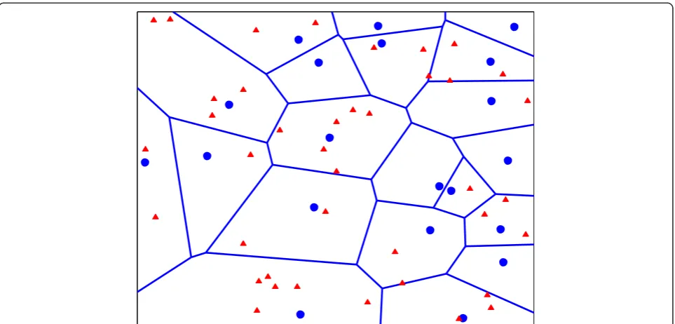
In the designed three-step EE optimization for the CP/ UP adaptation, the first step aims at constructing a seamless deployment of the CP with minimum transmis-sion power. The Voronoi Diagram, a geometric structure in the computational geometry, divides the space into a number of regions consisting of all the points closer to a specific site than to any other. As energy consumption is proportional to distance, the Voronoi Diagram also de-fines regions where less energy consumption is required. In order to achieve better EE in the CP construction and adaptation, we construct Voronoi coverage area for the Controlling-AEs. The Data-AEs located within the Voronoi coverage area are controlled by the correspond-ing Controllcorrespond-ing-AE.
distance between the ith Controlling-AE and a pos-ition x. Therefore, the Voronoi coverage of the ith Controlling-AE is defined as
V or cð Þ ¼i x∈R2 ∀j≠i;dEðci;xÞ<dE cj;x
ð4Þ In order to further adapt the transmission power of Controlling-AE with updated AE deployment or coverage area, the Voronoi coverage can be redefined based on the pathloss between the Controlling-AE and point x. Let α(ci,x)t be the pathloss between the ith
Controlling-AE and the position x at time slot t, the Voronoi coverage will be revised as
V or cð Þi t ¼ x∈R2 ∀j≠i;αðci;xÞt<α cj;x
t
o
n
ð5Þ Then, the whole CP can be formed into the expres-sion as ∪ 1 ≤ i ≤ nVor(ci). According to this definition,
any position in the Voronoi coverage area is closer to its Voronoi Controlling-AE than any others, which yields less power consumption. As a consequence, the re-quired transmission power for the Controlling-AE is minimized.
The simulation evaluation of the proposed CP con-struction and adaptation could be found in Section 6.
4 User-centric UP construction with joint AE and subchannel allocation
For the second step of the designed optimization process, the initial deployment of the UP construction for each user should be set up with the available sys-tem resources. Based on FNA, AE is released as a new
dimensional radio resource for allocation and scheduling. By jointly allocating the AE and subchannel resources, the on-demand user-centric UP is constructed with the user’s QoS requirement. The AEs’ transmission powers are allocated equally in this step. Moreover, the trans-mission power will be further adjusted based on game theory in the third step.
4.1 Joint resource allocation model for the UP construction
Assume that there areNData-AEs located in the net-work with two types of AEs, including the Macro AE and Small Cell AE. The bandwidth of each AE is the same and is divided intoM subchannels. We set Pi as
the maximum transmission power of the ith Data-AE. Meanwhile, K users are randomly distributed in the coverage area of the FNA, including K1 users with
guaranteed bit rate (GBR) service and K2 users with
non-GBR service. Each subchannel of an AE can only be allocated to one user. That is, we do not consider a space division multiple access (SDMA) scenario.
According to the concepts of FNA, in order to reduce the inter-AE interference and improve the cap-acity performance, users can use coordination tech-niques to receive signals from more than one AE in the same time slot. LetAmk represent the serving set of userk on subchannelm, while Am
k is the complement set of Amk. The instantaneous received signal to inter-ference and noise ratio (SINR) on subchannel m for userkis given by:
γm
where hmi;k denotes the complex channel response between AEi and userk on subchannelm, nmk denotes the additive white Gaussian noise with covarianceσ2and
piis the transmission power of AEi to the serving user.
The transmission powers for the AEs are allocated to its serving users equally in this step for decreasing the complexity of the multi-dimensional joint resource allo-cations. The power adjustment for the UP adaptation will be conducted further in the last optimization step.
The data rate allocated to userkon subchannelmcan be calculated as [12]:
Rmk ¼Blog21þγmk ð7Þ
The subchannel set allocated to user k is denoted as
Sk ⊆ {0, 1, 2, ⋯, M}, ∀ k, and we assume that at most NS subchannels can be assigned to one user. Thus, it is
obvious that |Sk|≤Ns,∀k, where“||”denotes the
cardin-ality of the set. We assume that the serving set for userk
on all subchannels in Sk is selected form a common AE
set. Ak ⊆ {0, 1, 2, ⋯, N + 1}, ∀ k, i.e., Amk⊆Ak;∀m∈
Sk;∀k. That is, Amk may contain all elements or partial elements in Ak. Assume that the maximal number of
elements in Ak isNa, i.e., |Ak| ≤ Na, ∀ k.
Hence, the instantaneous data rate for the user kcan be given by:
Rk¼
X
m∈Sk
Rmk ð8Þ
In order to quantify the different QoS requirements of users, the utility theory in economics is introduced to describe the characteristics of service by mapping the data rate to the user satisfaction level [13]. According to the user service QoS constraints, the utility functions of the GBR and non-GBR service are verified as the S-shaped function and convex function correspondingly [13, 14]. To satisfy these two types of services simultaneously, the utility function U(r) of all types of service is extracted from [15].
U rð Þ ¼ E
AþBe−C rð−dÞþD ð9Þ
where ris the data rate allocated to user; R is the total resource of the system;Cmainly influences the slope of the curve; A, B, D, E mainly effect the range of utility value; and d is the inflection point of the utility function, which indicates the user requirement of re-source. By setting different parameter values, the utility function can present different characteristics,
both the S-shaped function and the convex function. The utility functions of the GBR serviceUreal(r) and non-GBR serviceUnon-real(r) are obtained from Equation 9 [15].
The system utility is defined as the linear weighted sum of all users’ utility values. In Equation 10, λ rep-resents the priority of GBR service and μ represent the priority of non-GBR service. These two weights are constrained by λ, μ ∈ [0, 1] and λ + μ = 1.
The system utility can be further extended to in-clude more types of service. Since the utility value represents the satisfaction level of users, the system utility indeed represents all users’ satisfaction level, which can provide a better reflection of system per-formance than throughput.
4.2 Generic algorithm-based centralized resource allocation
In the FNA, the UP construction process is jointly and simultaneously allocating two dimensions of resources (AEs and subchannels) to users with different QoS requirements. Such a multi-dimensional resource alloca-tion problem can be solved by using the resource pooling-based centralized RRM scheme [9]. The above scheme is processed by the CPE to manage all of the available resources uniformly. Since the optimization problem of centralized resource allocation has a large and complex search space, genetic algorithm (GA) is implemented to obtain near-optimal solutions with a relatively fast convergence speed.
Based on GA, chromosome, which is a two-dimensional integer matrix, is used to represent the potential resource allocation solution. Each row of the matrix represents the resource allocation strategy for the specific user. More-over, each row can be further divided into several parts. Each part lists the allocated elements of a particular di-mension of resource. In particular, the chromosomeGin the following GA process is given by:
containingNaintegers indicates the allocated AEs, while the second part containingNsintegers lists the allocated subchannels. The initial population which includes Np chromosomes is generated by a random process.
Fitness function is constructed by the system utility function, which is the sum of all users’utility values. It can be used to evaluate the chromosomes. The larger the fitness value is, the better the solution is. Thus, the optimized objective is to maximize the fitness value that is to maximize the system utility. Since the utility value represents the satisfaction level of user, the proposed al-gorithm tends to meet the requirements of two types of services simultaneously under the three constraints in the user-centric UP constructions process. Specifically, we assume that at mostNaout ofN AEs andNsout of Msubchannels can be allocated to userk. In addition to AE and subchannel limitations, we also apply the con-straint derived from Equation 2 into the power limita-tion where we choose the minimum value between the two power constraintsPi(maximum transmission power
limitation) andpc-P(di). By using such constraint, we are
able to guarantee that the coverage of UPs will not sur-pass the CP coverage required in Section 3.
maxF¼ maxUsystem
The chromosomes will be passed to the next gener-ation through a four-step breeding process including Selection, Crossover, Mutation, and Modification.
First of all, a pair of parent individuals is selected based on the so-called“Roulette Wheel Selection”, such that the higher the fitness, the greater the opportunity for the individual to be selected. The possibility of chromosomeGibeing selected is:
p Gð Þ ¼i
chromosome Gi. Note that the selected chromosomes
are still in the population, and as a result, it is entirely likely that a chromosome is selected more than once.
Then, two children are generated by combining their par-ent’s genes. In particular, a crossover point is first chosen randomly at a certain column of the two given chromo-somes. Next, in order to form the first offspring, all the row
vectors before the crossover point of the first matrix will combine with the row vectors after the crossover point of the second matrix. The second offspring is generated in the opposite way. Herein, the crossover process is illustrated.
Assume two selected parent individuals A and B as follows: Suppose that the crossover point is located between
b1,1andb1,2. Then the two children chromosomes C and
D can be expressed as:
C¼ In this way, the offsprings are expected to provide better chromosomes with their parents’partial characteristics.
After the above processes, all of the children will go through the mutation operation to avoid converging to a local optimized solution. Since the individuals generated by crossover and mutation may no longer satisfy system constraints, some modification should be made.
times. The whole population will evolve from generation to generation and gradually converge to the optimized solution. When the algorithm is terminated, the central-ized resource allocation solution is based on the best in-dividualGbestt among the current population.
Using the joint resource allocation strategy of AEs and subchannels in theGbest, the UP is constructed with equal transmission power allocation mentioned before, where the transmission power of each serving set Data-AE isPi, i ∈
{1, 2,⋯,N}. After that, based on the UP construction pa-rameters, the UP adaptation via a power adjustment scheme can be implemented to further optimize the EE performance.
5 UP adaptation with game theory-based power adjustment
Based on above CP and UP construction, game theory could be further implemented as a power adjustment strategy for the UP adaptation in order to maximize the system EE. The non-cooperative game model with the pricing function is used to achieve the optimized system EE for the Data-AEs. Here, penalty is defined as the ex-cessive power consumption from Macro Data-AEs, which yields severe interferences. The existence and uniqueness of the Nash Equilibrium for the proposed game model will also be verified.
5.1 Game theory model for the UP adaptation
As we assumed above, the FNA network consists of N1
Macro Data-AEs and N2Small Cell AEs. One
Data-AE is able to serve several users within its coverage area. It is assumed that there is only one scheduled active user in each serving set during each signaling slot. Let k ∈
{1, 2,⋯,N} denote the scheduled userk. According to the results of Gbest and pi, i ∈{1, 2, ⋯, N} derived in
the UP construction step, the received SINR on subchannel
mfor the scheduled userkcan be expressed as:
γm
pi are the aggregate
SINR and transmission power of the scheduled user k, respectively. Considering the user k’s QoS requirement, its received SINR has the constraint as γk≥γthreshold
k . But
the threshold γthreshold
k for GBR service and non-GBR service are different.
5.2 UP adaption based on game theory
The UP Adaption focuses on the transmission power of serving set Data-AEs. Based on the game theory, we propose a power adjustment scheme for the system EE
optimization from the perspective of Data-AEs. Each Data-AE within the serving set will choose a reasonable transmission power to maximize its own utility of EE per-formance, which is a typical non-cooperative N-player game problem. Let G= [N, {pk}, {uk(pk, γk|P‐k)}] denote
the Non-cooperative Power adjustment Game with Pri-cing (NPGP), where
N= {1, 2,…,N} is the index of the serving set Data-AE.
{pk} = {pk|pk∈[0,pmax]} are the transmission power of serving set Data-AEs for userkandpmax> 0 is the maximum power constraint of the corresponding Data-AEs.
Let {uk(pk, γk|p‐k) denote the utility of the scheduled
user k, where γk and pk is the aggregated SINR and
transmission power of the userk respectively.p-k is the
vector of transmission power of all serving set Data-AEs other than the serving set Data-AEs for userk.
Considering the energy efficiency measured in bit/ Joule [16], the utility function of the serving set Data-AEs for userkis defined as:
uk notes the linear pricing for the user k. Both the ak and bkare positive factors.
f(γk) is defined as:
f γk ¼1−e−γ2k ð20Þ
which means that the revenue of the userkwill increase slowly asγkincreases [17].
The pricing bkpk will ensure that the serving set
Data-AEs for the user kcould be penalized when they cause serious interference to other users with more transmission powers.
Finally, the EE optimization problem for the UP adap-tion is formulated as the game model:
max 0≤pk≤pmax
uk pk;γkjp‐kÞ;∀k¼1;2;…;N
ð21Þ
5.3 Nash Equilibrium for the power adjustment game The Nash Equilibrium is a steady state that offers a predictable outcome of a game, where Data-AEs com-pete with selfish actions through self-optimization and converge to a point that no Data-AEs wish to deviate unilaterally. For the proposed game model (21), the Nash Equilibrium is defined as:
Suppose pk;∀k¼1;2;…;N is a solution for (21). Hence, the point p* is a Nash Equilibrium for the pro-posed non-cooperative game if for any p, the following conditions are satisfied:
uk pk
;γ
k
p
−k
j Þ≥uk pk;γkjp−kÞ;∀k¼1;2;…;N
ð22Þ
The proposed game model with pricing in this paper is a supermodular game [18]. The existence and unique-ness of the Nash Equilibrium will be verified as follows.
(1) Existence of Nash Equilibrium
Theorem 1:
The set of Nash Equilibria of a supermodular game is nonempty. Furthermore, the Nash set has a largest elem-ent and a smallest elemelem-ent.
A proof of the theorem can be found in [19]. LetE de-note the set of Nash Equilibria. LetpSand pLdenote the
smallest and the largest elements of E respectively. The theorem states that all the equilibria p ∈ E are located such thatpS<p<pL.
We introduce a totally asynchronous algorithm that generates a sequence of powers that converges to the smallest Nash EquilibriumpS. Suppose that the serving
set Data-AEs for userk update their power at time in-stances given by the setTk= {tk1,tk2,tk3,…} wheretkl< tk(l+ 1)and fortk0= 0 allk. DefineT= {τ1,τ2,τ3,…} as
the set of update instancesT1∪ T2∪…∪TNsorted in
increasing order. Assume that there are no two time in-stances in set T that are exactly the same. The algo-rithm for finding the Nash Equilibrium is designed as follows.
Algorithm 1:
Let us consider the proposed non-cooperative power adjustment game with pricing as given in (21). We will generate a sequence of the transmission powers:
1) Set the initial power vector at timet= 0:p=p(0). Also letl= 1.
2) For alllsuch thatτl∈T
For all serving set Data-AEs for the userksuch that τl∈Tk
i. Givenp(τl−1), computepk* = arg maxuk(pk,yk|p−k) ii. Ifyk≥ythresholdk
Thenpkð Þ ¼tl min pk;pmax
. else
Remove userkin this iteration and continue the algorithm in next iteration [20].
end For. end For.
Theorem 2:
The proposed Algorithm 1 converges to a Nash Equilib-rium of the NPGP. Furthermore, it is the smallest equilib-riumpS, in the set of Nash Equilibria.
The proof can be found in [17], which implies that the Nash Equilibrium in the proposed NPGP exists and can be reached from either the top or the bottom of the strategy space with Algorithm 1. Since we do not know if there is a unique equilibrium, we compare the equilib-rium in the Nash setEto determine if there exists a sin-gle equilibrium that dominates all other equilibria. Indeed, we can show that pS is the best equilibrium in
the setE.
(2) Uniqueness of Nash Equilibrium
Theorem 3:
Ifx,y∈Eare two Nash Equilibria in NPGP andx≥y, thenuk(x)≤uk(y) for allk.
Proof:
Notice that, for fixed pk, the utility uk¼ak fð Þγk
pk −bkpk decreases with increasing p-k for allk. Therefore, since x−k≥y−k, we have:
ukðxk;x−kÞ≤ðxk;y‐kÞ ð23Þ
Also, by definition of Nash Equilibrium and since yis a Nash Equilibrium of NPGP, we have:
ukðxk;y−kÞ≤uk yk;y−k
ð24Þ By the above equations,
ukð Þx ≤ukð Þy ð25Þ
According to the Theorem 3, we know that smaller Nash Equilibrium leads to higher utilities for all users. SincepS<pfor allp∈E, we conclude that for allp∈E,
ukð Þps ≥ukð Þp for allk ð26Þ
This result implies that, in case the NPGP has Nash Equilibria, the one that yields highest utilities is the Nash Equilibrium with the minimum total transmission powers.
In conclusion, the existence and the uniqueness of the Nash Equilibrium for the proposed NPGP have been proved. It means that the transmission power of the serv-ing set Data-AEs at the Nash Equilibrium are regarded as a reasonable solution for the EE improvement of the UP adaption scheme.
6 Simulation evaluations
and subchannel allocation are provided. After obtaining the UP construction results, the non-cooperative game model-based power adjustment for the UP adaptation are evaluated with the EE performances. This is the last step for the whole CP/UP adaptation solutions on the FNA fea-tured networks.
6.1 Simulation environment
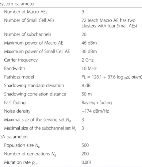
Based on the deployment scenario of the FNA, the hetero-geneous coverage environment is set up, which contains different types of AEs connected with one centralized CPE. There are 9 Macro AEs and 72 Small Cell AEs generated in a 2 × 2-km-square coverage area. In the coverage of each Macro AE, Small Cell AEs are randomly distributed as sev-eral clusters. The CPE constructs and maintains the CP by choosing Controlling-AEs to guarantee the signaling re-quirements in the coverage area. In addition, the CPE also constructs and updates the user-centric UP by allocating Data-AEs to make up the coordinated serving set to fulfill the user QoS requirements.
The simulations use parameters that are based on the guidelines for 3GPP channel model [21] and that are carried out through the Matlab platform. There are total 20 subchannels that can be fully reused by all the AEs. The channel conditions take into account pathloss, shadow fading, and Rayleigh fading. The maximum num-ber of AEs in the coordinated serving set is limited to 3. Furthermore, in order to guarantee fairness among users, the maximum number of subchannels that can be allo-cated to each user is also limited to 3. More detailed simu-lation settings including the system and GA parameters for the joint resource allocation are listed in Table 1.
6.2 Simulation results and analyses
(1) The CP construction and adaptation with Voronoi Diagram.
According to the proposed Voronoi Diagram-based CP construction and adaptation scheme, the Controlling-AEs are selected to construct the CP for serving the whole coverage area. That is, the selected Controlling-AEs need to cover the farthest Voronoi vertices of the coverage area, while the transmission power is adapted with the actual network deployments.
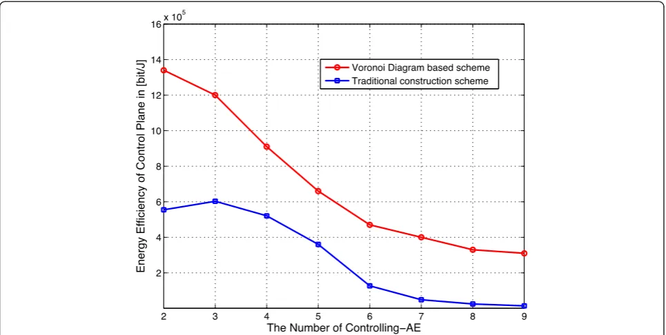
Traditionally, the CP is constructed based on network planning, which is mainly uniform deployed within the coverage area. Furthermore, the transmission power of CP is set as the maximum transmission power of the BS. In this paper, the EE performance of the proposed CP construction and adaptation scheme is compared with the traditional CP construction scheme as the baseline. The simulation results are collected in the generated coverage area with choosing different numbers of Controlling-AEs.
Figure 3 shows the EE performance versus different numbers of Controlling-AE selected for the CP con-struction. As expected, the Voronoi Diagram-based CP construction and adaptation scheme outperforms the traditional CP construction scheme. As the number of Controlling-AEs in the generated coverage area in-creases, the EE performances of both schemes experi-ence a decline. This is because the decrease in the inter-site distance between Controlling-AEs actually causes unnecessary energy consumption. For the cover-age area generated in the simulation, less Controlling-AE are enough to handle all the signaling coverage.
(2) The user-centric UP construction with GA-based joint AE and subchannel allocation.
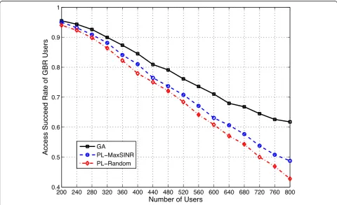
The proposed GA-based resource allocation scheme is abbreviated to “GA” in the following simulation re-sults. The performance metrics of the system utility, user access succeed rate, and system throughput are evaluated. In detail, the system utility is the sum of all users’utility values, which reflects the satisfaction level of users. The access succeed rate is defined as the pro-portion that GBR users’ QoS requirement is satisfied. That is, the ratio between the number of GBR users (whose required data rate are reached) and the total number of GBR users. The number of users is increas-ing from 200 to 800, while the number of users with GBR service and non-GBR service remains the same in this step.
Table 1Simulation setting
System parameter
Number of Macro AEs 9
Number of Small Cell AEs 72 (each Macro AE has two clusters with four Small AEs)
Number of subchannels 20
Maximum power of Macro AE 46 dBm
Maximum power of Small Cell AE 30 dBm
Carrier frequency 2 GHz
Bandwidth 10 MHz
Pathloss model PL= 128.1 + 37.6 log10d,d(km)
Shadowing standard deviation 8 dB
Shadowing correlation distance 50 m
Fast fading Rayleigh fading
Noise density −174 dBm/Hz
Maximal size of the serving setNa 3
Maximal size of the subchannel setNs 3
GA parameters
Population sizeNp 500
Number of generationsNg 200
During the simulations, two algorithms are used as the comparisons. One is the pathloss-based AE selection for the user-centric serving set construction and random-ized subchannel set allocation (abbreviate to “ PL-Ran-dom”). Each user will selectNabest AEs with the lowest
pathloss between the AEs and the user. Then the user will be randomly allocated the common available sub-channels of all the AEs in the serving set.
The other compared algorithm is the pathloss-based user-centric serving set construction and maximum SINR subchannel set allocation (abbreviate to “ PL-Max-SINR”). Each user will selectNabest AEs with the lowest
pathloss between the AEs and the user. Then the user will be allocated the common available subchannels of the selected AEs, which tend to provide the highest SINR.
The simulation results of the system utility, the user access succeed rate, and the system throughput are plot-ted as Figs. 4, 5 and 6, respectively.
As shown in Fig. 4, the performance of the proposed UP construction scheme is shown in terms of the system utility value versus the number of users. It is observed that the GA-based scheme achieves the highest system utility value, PL-MaxSINR ranks second and PL-Random has the lowest performance. Note that the performance gap between GA and other algorithms becomes larger as the number of users increases. This is mainly because when the resources are not sufficient, the optimized resource man-agement can allocate limited resources more effectively based on different user QoS requirements, which improves the system utility further.
For GBR users, the satisfaction level can be measured by access succeed rate, the larger the better. For in-stance, the access succeed rate 0.8 means that 80 % of GBR users’ prescribed QoS requirements are fulfilled. As shown in Fig. 5, the proposed GA-based algorithm can achieve larger access succeed rate than the other so-lutions (PL-MaxSINR, PL-Random), which means the GA-based scheme tends to guarantee that a higher number of GBR users will meet the required data rate. This is because the S-shaped utility function curve of the GBR service rises rapidly at the required bit rate, and allocating enough resources to the GBR users will have more contribution to the overall system utility, compared to allocating more resources to the non-real-time services.
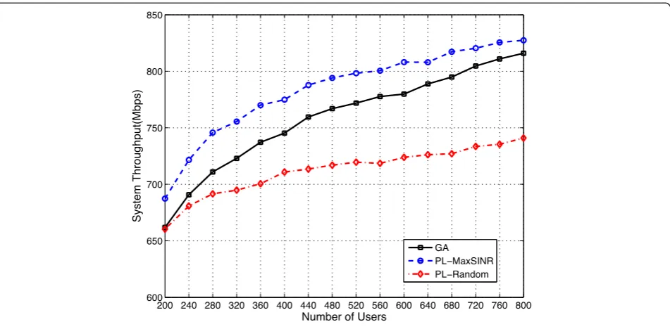
The system throughput performances of these three algorithms against the number of users were also simu-lated. In Fig. 6, we can observe that the PL-MaxSINR al-gorithm, which pursues maximal throughput, ranks first as expected. The GA-based scheme ranks second and also achieves relative high system throughput. This con-firms that the GA-based scheme can achieve a better balance between user satisfaction and system through-put. In other words, it can provide better resource utilization, while just slightly worse system throughput.
Since the computational complexity of the solution to NP-Hard problems is an important factor for evaluating its performance, the complexities of the proposed GA-based algorithm and comparison schemes will be ana-lyzed as follows.
The heuristics solution, GA, is implemented here for handling the optimization problem of the two-dimensional resource allocation, which is proved as a NP-Hard problem. The merits of the GA are finding the near-optimal solution with lower computational complexity and fast converging
speed. For the NP-Hard problem, the exhausted search (ES) is a way to solve the problem by searching for the opti-mal solution.
As assumed before, there are total N AEs and the bandwidth of each AE is divided into M subchannels, Fig. 4System utility of the user-centric UP construction
the computational complexity of the K user ES will be
K NK NaMK NsN aNs
, where Na denotes the maximal
AE number in a serving set andNsdenotes the maximal
subchannel number in a subchannel set. We can infer from the above equation that ES is too complex to be implemented in our evaluation scenario.
For the GA-based scheme, the computational com-plexity mainly comes from the fitness evaluation process, which can be measured with the number of SINR calcu-lations. For other comparison schemes that we consid-ered, namely the PL-Random and PL-MaxSINR, their computational complexities are measured with the num-ber of SINR calculations in the resource allocation and criteria measurement procedure.
The following Table 2 lists the computational complexity of four different schemes, where the complexity is calcu-lated for the worst case. In GA, Np and Ng denote the
population size and the iterations, respectively. As we can see, the complexity of PL-Random is the lowest. Using the order of magnitude provided in the system parameter (Table 1), it can be concluded that GA has an equal com-plexity to PL-MaxSINR but with superior performances as shown above. Thus, compared to the optimal ES, the com-plexity of the GA is much lower, while the performance is near-optimal.
(3) The UP adaptation with game theory-based power adjustment.
Based on the CP and UP construction results in the above steps, the user-centric UP will be further adapted by the proposed non-cooperative game model-based power adjustment. As assumed before, there are total K users randomly distributed in the system, includingK1GBR
ser-vice users andK2non-GBR service users. Letη= K1/K2
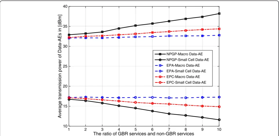
denote the ratio of users with GBR service to users with non-GBR service. The comparison algorithms include the equal transmission power allocation (EPA) derived in the second step with GA-based UP construction and another algorithm named as “efficient power control (EPC) scheme”[22]. The EPA scheme is compared as the per-formance baseline. The EPC scheme is proposed as the power control mechanism for the Small Cell HetNet sce-narios. The EPC scheme also employs the non-cooperative game model, but the utility and pricing function design are different than those used in our proposed scheme. The sys-tem EE performance and average transmission power of the Data-AEs at the Nash Equilibrium solution (abbreviate to “NPGP” scheme) versus the ratio η are evaluated re-spectively with Figs. 7 and 8.
As shown in the Fig. 7, we can observe that the aver-age achieved system EE performance of NPGP is better Fig. 6System throughput of the user-centric UP construction
Table 2Computational complexity
Scheme ES GA PL-MaxSINR PL-Random
Complexity OKNKNaMKNsNaNs OKNgNpNaNs OKMNsþKNaNs OðKNaNsÞ
than that for the EPA and EPC schemes. The system EE at the Nash Equilibrium solution of the proposed NPGP is much better than that of EPA at each value ofη. The utility function and pricing function design with the NPGP game model also show the gain of the EE per-formance over the EPC scheme.
Figure 8 compares serving set Data-AEs’average trans-mission power among the Nash Equilibrium solution of the NPGP, EPA, and EPC versus the user ratio η. As
observed from the simulations results, the serving set Small Cell Data-AEs’ average transmission powers at Nash Equilibrium are much lower than that of the EPA and EPC withηincreasing, which means that the trans-mission power of the Small Cell AEs are saved with the proposed NPGP scheme. For the average transmission power of Macro Data-AEs in the serving set, the NPGP at the Nash Equilibrium solution has larger transmission power requirements than that of the EPA and EPC The ratio of GBR services and non-GBR services
1 2 3 4 5 6 7 8 9 10
Av
er
ag
e
a
ch
ie
ve
d
E
E
in
[b
it/J]
105 106 107 108
NPGP EPA EPC
Fig. 7Average achieved system EE at the Nash Equilibrium
The ratio of GBR services and non-GBR services
1 2 3 4 5 6 7 8 9 10
Averag
e
transmi
ssi
o
n
p
ower
of
Data
-AEs
in
[dBm]
10 15 20 25 30 35 40
NPGP-Macro Data-AE NPGP-Small Cell Data-AE EPA-Macro Data-AE EPA-Small Cell Data-AE EPC-Macro Data-AE EPC-Small Cell Data-AE
scheme. This is due to the fact that the Macro Data-AE needs to cover the Macro cell edge users to guarantee their QoS requirements, especially with the increasing of GBR services. The users are randomly distributed in the whole coverage area, which means there are several GBR users located in the Macro coverage edge. The larger transmission power limitation lets the Macro Data-AE have the ability to handle the GBR requirements even at the edge of coverage. There is only about 7 % average in-crease of the Macro Data-AE transmission power com-pared with the NPGP scheme, which is still under the power limitation of the Macro Data-AE. Furthermore, since the number of Small Cell Data-AEs is much more than the Macro Data-AEs in the system, it is obvious that the proposed NPGP-based UP adaptation solution is helpful to save the transmission power and improve the system EE.
7 Conclusions
Based on the frameless network architecture, we propose a control plane/user plane adaptation strategy for system energy efficiency improvement. The constraints for the CP/UP separation-based adaptation are presented and the system EE performance optimization problem is de-signed as a three-step scheme. Firstly, the CP is con-structed with the Voronoi Diagram to achieve better system EE. Secondly, we constructed the user-centric UP for each specific user and considered user-centric serv-ing set construction by jointly allocatserv-ing resources. The AEs and subchannels are jointly allocated by the GA al-gorithm with equal power allocations for different QoS services, while the power adjustments are further han-dled by the third step with game theory solutions for the system EE optimization. The non-cooperative power ad-justment game model with pricing is given and the corresponding Nash Equilibrium is solved with the verifi-cations of its existence and uniqueness. Finally, the per-formance evaluations are conducted with the system-level simulations. According to the simulation results, the CP/ UP adaptation-based system EE performances are im-proved. Moreover, the user-centric UP construction scheme achieves a better user satisfaction level and access succeed user rate. Hence, considering the constraints on signaling and data transmission, the CP/UP adaptation is an innovative method for further improving the system energy efficiency.
Competing interests
The authors declare that they have no competing interests.
Acknowledgements
This paper is supported by the Natural and Science Foundation of China under Grant No. 61471068, Beijing Nova Programme No. Z131101000413030 and National High Technology Research and Development Program of China No. 2014AA01A701. The authors also thank the reviewers and editors for their thorough review and comments.
Author details 1
National Engineering Laboratory for Mobile Network Security, Beijing University of Posts and Telecommunications, Beijing 100876, China.2Division of Terminal Technology, China Mobile Research Institute, Beijing 100053, China.3Intellectual Property Department, Tendyron Corporation, Beijing 100083, China.
Received: 1 September 2014 Accepted: 1 June 2015
References
1. JG Andrews, Seven ways that HetNets are a cellular paradigm shift. Commun. Mag. IEEE51(3), 136–144 (2013)
2. L Hanzo, H Haas, S Imre, D O’Brien, M Rupp, L Gyongyosi, Wireless myths, realities, and futures: from 3G/4G to optical and quantum wireless. Proc. IEEE100, 1853–1888 (2012)
3. 3GPP, TR 36.839 v11.1.0, Mobility enhancements in heterogeneous networks (3GPP, Sophia-Antipolis, 2012)
4. 3GPP, TR 36.842 v0.4.1, Study on small cell enhancements for E-UTRA and E-UTRAN - higher layer aspects (3GPP, Sophia-Antipolis, 2013)
5. 3GPP, TR 36.814 v11.1.0, Further advancements for E-UTRA physical layer aspects (3GPP, Sophia-Antipolis, 2013)
6. China Mobile Research Institute, C-RAN, The road towards green RAN, White Paper, v3.0 (2013)
7. M Yang, Y Li, D Jin, OpenRAN: a software-defined RAN architecture via virtualization. ACM SIGCOMM43(4), 549–550 (2013)
8. X Jin, L E Li, L Vanbever, J Rexford, Softcell: Scalable and flexible cellular core network architecture. ACM conference on Emerging networking experiments and technologies, Santa Barbara, 2013.
9. X Xu, D Wang, X Tao, T Svensson, Resource pooling for frameless network architecture with adaptive resource allocation. Sci. China Inf. Sci56(12), 83–94 (2013)
10. X Xu, H Zhang, X Dai, Y Hou, X Tao, P Zhang, SDN based next generation mobile network with service slicing and trials. China Commun.11(2), 65–77 (2014) 11. A Goldsmith,Wireless Communications(Cambridge University press,
Cambridge, 2005)
12. D Wang, X Xu, X Tao,Joint Scheduling and Resource Allocation Based on Genetic Algorithm for Coordinated Multi-Point Transmission Using Adaptive
Modulation(IEEE PIMRC, Sydney, 2012)
13. C Liu, L Shi, B Liu,Utility-based Bandwidth Allocation for Triple-Play Services
(ECUMN, Toulouse, 2007)
14. Z Niu, L Wang, X Duan, Utility-based radio re-source optimization for multimedia DS-CDMA systems. ACTA ELECTRONICA SINICA.32(010), 1594–1599 (2004)
15. L Chen, W Chen, Utility based resource allocation in wireless networks. Journal of Beijing University of Posts and Telecommunications3(6), 58–63 (2010)
16. YS Soh, TQS Quek, M Kountouris, Energy efficient heterogeneous cellular networks. IEEE J Selected Areas Commun.31(5), 840–850 (2013) 17. CU Saraydar, NB Mandayam, DJ Goodman, Efficient power control via pricing
in wireless data networks. IEEE Trans. Commun.50(2), 291–303 (2002) 18. DM Topkis, Equilibrium points in nonzero Sum n-person submodular games.
SIAM J. Control Optimization17(6), 773–787 (1979)
19. DM Topkis,Supermodularity and Complementarity(Princeton Univ Press, Princeton, 1998)
20. M Andersin, Z Rosberg, J Zander, Gradual removals in cellular PCS with constrained power control and noise. Wirel. Netw2(1), 27–43 (1996) 21. 3GPP, TR25.996 v.11.0.0, Spatial channel model for multiple input multiple
output (MIMO) simulations (3GPP, Sophia-Antipolis, 2012)
![arxiv: v3 [math.fa] 8 Feb 2020](data:image/gif;base64,R0lGODlhAQABAIAAAP///wAAACH5BAEAAAAALAAAAAABAAEAAAICRAEAOw==)