ISSN(Online): 2319-8753 ISSN (Print): 2347-6710
I
nternational
J
ournal of
I
nnovative
R
esearch in
S
cience,
E
ngineering and
T
echnology
(An ISO 3297: 2007 Certified Organization)
Website: www.ijirset.com
Vol. 6, Issue 4, April 2017
Optimum Performance of Shear Wall Frame
Structure by Changing Location of Shear Wall
Gunj D. Rathod1, Shubham S. Hande2, Amol V. Gorle3
U.G. Student, Department of Civil Engineering, Jagadambha Engineering College, Maharashtra, India1
U.G. Student, Department of Civil Engineering, Jagadambha Engineering College, Maharashtra, India2
Assistant professor, Department of Civil Engineering, Jagadambha Engineering College, Maharashtra, India3
ABSTRACT: Human life is priceless, there is nothing more valuable than human life. Earthquake is one of the natural
disasters which cause huge loss of human life. The example of Bhuj earthquake is fresh before us which had occurred in 2001 in Gujarat which had result in loss of human life more than 13800 and more and even great finance loss. So from the history is getting that Earthquakes don’t kill people, but buildings kill people. So, now it is need of today’s era to built earthquake resistant structure & tries to save not only the life of people but also the economic losses. For resisting earthquake forces provided lateral load resisting system i.e. beam column, shear wall, diagrid systems etc. This paper is an attempt to establish best location of shear wall system to get optimum performance of structure. For that four models constructed in E-TABS 2015 software on the basis of changing location of shear wall. Here consider 20 storey model and required provisions for shear wall is to be applied. In all above system the weight is same and material is constant in lateral load resisting system. Here to make earthquake resistance structure, response spectrum method is to be used and all the data required for such type of method is to be taken from IS code i.e. IS 1893 (part 1): 2002 and for wind resistance, gust factor method is to be used and all the data required for this method is to be taken from IS code i.e. IS 875 (part 3): 1987. All this system compare on the basis of Storey displacement, Storey forces, Time period.
KEYWORDS:Storey displacement, Modal Time period, Shear wall, ETABS, Response spectrum.
I. INTRODUCTION
Now a days India moving toward become the developed country through economy, huminite for that infrastructure places an important role. Bhuj Earthquake, Killari (Latur) Earthquake, Chamoli Earthquake, Jabalpur Earthquake, Uttarkashi Earthquake etc. this types of earthquake cause loss of lives and damages to the infrastructure. This types of moment move India to lack behind from become Developed country. In the earthquake occurrence area Random rubble stone masonry structure, Cement concrete block construction, Earthen building have been observed mostly. It is important to construct the structure resistant to lateral loads i.e. especially wind load and earthquake load is to be considered. For that applying some provisions to the structure and main provision is shear wall constructing in the structure. Construction of shear wall in the structure is very tedious job and it requires high construction cost but it is cheaper than different lateral load resisting system i.e. Diagrid system, Outrigger system etc.
In lateral load only two loads act on the structure i.e. earthquake load and wind load. Seismic zone plays an important role in the earthquake resistant design of building structures because the zone factor changes according to the intensity of earthquake. In high rise structure wind load is to be considered for that required location of structure, height of structure etc.
Objective
To determine Story displacement, Modal time period, Story forces in both vertical and horizontal direction.
To observe performance of shear wall under seismic and wind loading.
ISSN(Online): 2319-8753 ISSN (Print): 2347-6710
I
nternational
J
ournal of
I
nnovative
R
esearch in
S
cience,
E
ngineering and
T
echnology
(An ISO 3297: 2007 Certified Organization)
Website: www.ijirset.com
Vol. 6, Issue 4, April 2017
II. LITERATURE SURVEY
These are some literature reviews while preparing this paper.
M. D. Kevadkar, P. B. Kodag, Lateral load analysis of R.C.C building [5]. In this paper, they used shear wall in R.C. structure and steel bracing in steel structure used to resist lateral load as earthquake, wind blast etc. In which the RCC Building is modeled and analyzed in two parts 1) Model without bracing and shear wall. 2) Model with different shear wall with different bracing system, the computer added analysis is done by using E-TABS. They have concluded that this concept can used to strengthen the structure. Steel bracing reduces flexure and shear demand on beams and column and transfer the lateral load through axial load mechanism. Capacity of steel braced structure is more as compare to the shear wall structure.
Thejaswini R. M. and Rashmi A. R, Comparative study and analysis of different lateral load resisting structural systems [6]. In this paper the analysis is done to understand the realistic performance of the building during earthquake and under the excessive wind pressure as well as to select structural system for a tall building to stay in good condition with effect of gravity, live load and external lateral load, moment, shear force and torque with acceptable strength and stiffness. For this research work they have modelled a geometrically irregular 14 storey RCC high rise building with different forms of structural system, such as rigid frame structure, core wall structure, and shear wall structure with different configurations of shear wall location, tube structure and outrigger structure. Results of the analysis reveal that the values of displacement were less in tube structure and outrigger structural system. The authors have also stated that in geometrically irregular structure; stability of structure will boost and the columns sway can be reduced by implementing L-shaped shear wall along the corners of the structure.
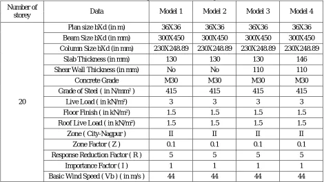
III.BUILDING CONFIGURATION
Table 1 Required data for Modelling
Number of
storey Data Model 1 Model 2 Model 3 Model 4
20
Plan size bXd (in m) 36X36 36X36 36X36 36X36
Beam Size bXd (in mm) 300X450 300X450 300X450 300X450
Column Size bXd (in mm) 230X248.89 230X248.89 230X248.89 230X248.89
Slab Thickness (in mm) 130 130 130 146
Shear Wall Thickness (in mm) No No 110 110
Concrete Grade M30 M30 M30 M30
Grade of Steel ( in N/mm² ) 415 415 415 415
Live Load ( in kN/m²) 3 3 3 3
Floor Finish ( in kN/m²) 1.5 1.5 1.5 1.5
Roof Live Load ( in kN/m²) 1.5 1.5 1.5 1.5
Zone ( City-Nagpur ) II II II II
Zone Factor ( Z ) 0.1 0.1 0.1 0.1
Response Reduction Factor ( R ) 5 5 5 5
Importance Factor ( I ) 1 1 1 1
ISSN(Online): 2319-8753 ISSN (Print): 2347-6710
I
nternational
J
ournal of
I
nnovative
R
esearch in
S
cience,
E
ngineering and
T
echnology
(An ISO 3297: 2007 Certified Organization)
Website: www.ijirset.com
Vol. 6, Issue 4, April 2017
IV.CLASSIFICATION OF MODEL BASED ON LOCATION OF SHEAR WALL
1. Plan of models
Fig.1 Plan of Models
These are the plans of models which shows different position of shear wall. All the models have same building configuration and same load act on it
2. Elevation of Models
ISSN(Online): 2319-8753 ISSN (Print): 2347-6710
I
nternational
J
ournal of
I
nnovative
R
esearch in
S
cience,
E
ngineering and
T
echnology
(An ISO 3297: 2007 Certified Organization)
Website: www.ijirset.com
Vol. 6, Issue 4, April 2017
3. 3D View of Models
Fig.3 3D View of Models
V. EXPERIMENTAL RESULTS
1. Storey Forces
Fig.4 Storey Forces in X-Direction
ISSN(Online): 2319-8753 ISSN (Print): 2347-6710
I
nternational
J
ournal of
I
nnovative
R
esearch in
S
cience,
E
ngineering and
T
echnology
(An ISO 3297: 2007 Certified Organization)
Website: www.ijirset.com
Vol. 6, Issue 4, April 2017
2. Wind Forces
Fig.6 Wind Forces in X and Y Direction
3. Modal Time period
Fig.7 Modal Time period
4. Storey Displacement
ISSN(Online): 2319-8753 ISSN (Print): 2347-6710
I
nternational
J
ournal of
I
nnovative
R
esearch in
S
cience,
E
ngineering and
T
echnology
(An ISO 3297: 2007 Certified Organization)
Website: www.ijirset.com
Vol. 6, Issue 4, April 2017
Fig.9 Storey Displacement in Y- Direction
Fig.10 Storey Displacement due to Wind forces in X and Y Direction
VI. CONCLUSION
On the basis of above result, it observes that the Model 4 carries maximum Storey forces. Modal time period and storey displacement is less than other models. So it shows that Stiffness is maximum in Model 4 as compared to other models. So it can be concluded that optimum performance of Model 4 is best as compared to other models.
REFERENCES
[1] Shruti Badami, M. R. Suresh, “A study on behaviour of structural system for tall building subjected to lateral loads”, International journal of Engineering Research & Technology (IJERT).
[2] Ajinkya P. Gadkari, “Review on behavior of outrigger structural system in high rise building”, International journal of Engineering Development of Research.
[3] Venkta S. Kumar, Surendra Babu,Usha Kranti, “Shear wall-A review”, International journal of innovative research in science.
[4] M. D. Kevadkar,P. B. Kodag, “Lateral load analysis of RCC building”, International journal of Modern Engineering Research (IJMER),Vol.3,Issue3,page no.1428-1434,May-June2013.
[5] Tanha B.Shah, “literature Survey on Analysis of Multi-storey building considering hybrid structure”, International journal of innovative research and development.
[6] Tejaswini R. M.,Rashmi A. R, “Analysis and comparison of different lateral load resisting structural forms”, International journal of engineering research and technology.
[7] Kiran Parmar, Mazhar Dhankot, “Comparative study between dual system for lateral load resistance in buildings of variable heights”, International Engineering Research journal of & Technology, page no. 303-306.
ISSN(Online): 2319-8753 ISSN (Print): 2347-6710
I
nternational
J
ournal of
I
nnovative
R
esearch in
S
cience,
E
ngineering and
T
echnology
(An ISO 3297: 2007 Certified Organization)
Website: www.ijirset.com
Vol. 6, Issue 4, April 2017
[9] Abhijeet Baikerikar, Kanchan Kanagali, “Study of lateral load resisting system of variable heights in all soil types of high seismic zone”, International journal of Engineering Research & technology, page no. 109-119.
[10] Akshay A. Khanorkar, S. V. Denge, S. P. Raut,“Belt truss as lateral load resisting structural system for tall building”, International journal of Engineering Research & Technology, page no. 658-662.
[11] Piyush Gupta, Dr. Neeraja, “Analysis of various RCC lateral force resisting system and their comparison using –ETABS”, International journal of latest trends in engineering and technology,page no. 175-182.
[12] Prathith Hedge, Dr.Aakshatha Shetty, “Seismic analysis of RC frames using lateral load resisting system”, International journal of technical research and applications,Volume:04, Issue:03, May-June 2016, page no. 197-200.
[13] Navin R. Amin, Jason J. C. Louie, “Design of multiple framed tube high rise steel structures in seismic region”, page no. 347-354.
[14] IS:1893 (Part 1): 2002, “Criteria for earthquake resistant design of structures, part 1-general provisions and buildings”, (fifth revision), Bureau of Indian Standards, New Delhi, India.