Optimization of the Process Parameters of
Electro Discharge Machining Process for En8
Grade
N Rajiv Kumar1, K Ramanathan2
Assistant Professor, Department of Mechanical Engineering, Sriguru Institute of Technology, Coimbatore,
Tamilnadu, India1
U.G. Scholar, Department of Mechanical Engineering, Sriguru Institute of Technology, Coimbatore, Tamilnadu, India2
ABSTRACT: The Electrode discharge machining process was carried out on EN8 grade tool steel and its performance
characteristics has been studied for optimizing the machining parameters of EDM process. The experiments were carried out for different machining parameters such as pulse on time, pulse off time, gap voltage and peak current using Taguchi’s L9 orthogonal array. The machining characteristics consisting of surface roughness, material removal rate (MRR) and electrode wear ratio (EWR) has been studied for optimizing the machining parameters.
KEYWORDS: EDM; MRR; EWR; surface roughness; Taguchi’s L9 orthogonal array; pulse duration; peak current
I. INTRODUCTION
Electro discharge machining is a non-conventional machining process which uses high frequency electric sparks for causing erosion in the work piece and thereby removes the work piece material. The fields like space research, nuclear industry, missile technologies requires machining of newly developed advanced materials like super alloys, ceramics and composites which are difficult to machine economically with the conventional machining techniques. But, non-conventional techniques like EDM can be used to machine those advanced materials more economically and effectively [1]. The EDM process is also being widely used for manufacturing dies and moulds in manufacturing industries and also for manufacturing various components in automobile and aerospace industries [4]. High pulse time and high current density should be applied to have a minimum electrode wear [2]. The pulse duration and discharge currents are the main factors that has a greater influence on the machining time and surface quality of the work pieces produced [3]. The material removal rate (MRR) and surface roughness are being influenced by pulse on time and discharge currents [4]. The performance characteristics such as material removal rate, electrode wear ratio and surface roughness can all together be improved by using modified taguchi method [7].
II. RELATED WORK
The Electro discharge machining process using copper as electrode can be optimized for EN8 to enhance its machining characteristics. The steps involved are summarized as follows.
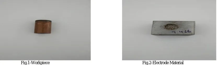
1. EN8 is chosen as the work-piece to be machined in EDM process. All the work-piece should be of same dimensions as in figure1. The cutting of work-piece is done by using wire cut EDM machine.
2. Copper is chosen as the electrode material. All the copper electrode should be of same dimension as in figure 2. The cutting of electrode is done using lathe machine
3. The parameters that are considered in this study are pulse on time, pulse off time, gap voltage and peak current. 4. Their experimental layout is created by using Taguchi’s L9 orthogonal array.
III. EXPERIMENT
SELECTION OF WORKPIECE:
The work piece used in this study is EN8 which is also known as 080M40. It is an unalloyed medium carbon steel with the composition as shown in the table below.
C % Si % Mn % Ni % Cr % Mo % S % P % Fe % 0.35 - 0.45 0.05 - 0.35 0.60 - 1.00
- - - 0.06Max 0.06Max Balance
Table 1-Composition of EN8 (Work-piece)
The maximum stress of this material is 700-850 N/mm2, minimum yield stress is 465 N/mm2, minimum elongation is 16% and harness is 201-255 BHN. It is widely used for hydraulic rams (chromed), key steel, medium torqued shafts, medium bending and compression loading applications. It also has a good corrosion resistance.
SELECTON OF ELECTRODE:
Copper is the electrode used in this study. The important properties of copper are high strength-to-weight ratio, resistance to corrosion by many chemicals, high thermal and electrical conductivity, non-toxicity, reflectivity, appearance, non-magnetic and ease of formability and of machinability.
Electrical resistivity (µΩ/cm) Electrical conductivity compared with silver (%) Thermal conductivity ( W/mK) Melting point (° C )
Specific heat ( cal/g ° C)
Specific gravity at
20 ° C (g/cm3 )
Coefficient of thermal expansion ( x 10 ° C-1)
1.96 92 268 – 389 1083 0.092 8.9 6.6
Table 2-Physical properties of Copper electrode
EXPERIMENTAL PLAN:
First of all, the electrode and the work-piece are cut according to the required dimension. The dimensions of electrode and work-piece should be same for all the experiments. The lathe machine is used to cut the electrode. For the work piece, the wire cut EDM machine is used for cutting all specimens in same dimension. The figure below shows the sample of work-piece and electrode used. The diameter of electrode is 10mm and the work-piece has a length of 110mm, breadth of 50mm and height of 65mm.
Fig.1-Workpiece Fig.2-Electrode Material
Symbols Parameters Units Level 1 Level 2 Level 3
A PULSE ON TIME (Ton)
µs 50 100 200
B PULSE OFF TIME (Toff)
µs 4 8 12
C GAP VOLTAGE (Vg)
V 100 120 130
D PEAK CURRENT (Ip)
A 35 37 40
Table 3-Machining parameters and their levels
L9 orthogonal array:
The Taguchi’s L9 orthogonal array is employed for doing experimentation. This L9 orthogonal array can be used to analyse the effect of four independent variable with each variable having three set values (level values). The experimental layout for the four machining parameters using the L9 orthogonal array is shown in Table 4. Experimental design using L9 orthogonal array is shown in table 5.
S.NO PULSE ON
TIME
PULSEOFF TIME
GAP VOLTAGE PEAK
CURRENT
1 1 1 1 1
2 1 2 2 2
3 1 3 3 3
4 2 1 2 3
5 2 2 3 1
6 2 3 1 2
7 3 1 3 2
8 3 2 1 3
9 3 3 2 1
Table 4-Layout of L9 orthogonal array
S.NO PULSE ON
TIME µs
PULSEOFF TIME
µs
GAP VOLTAGE V
PEAK CURRENT
A
1 50 4 100 35
2 50 8 120 37
3 50 12 130 40
4 100 4 120 40
5 100 8 130 35
6 100 12 100 37
7 200 4 130 37
8 200 8 100 40
9 200 12 120 35
Table 5-Experimental design using L9 orthogonal array
ELECTRO DISCHARGE MACHINING PROCESS:
completion of each machining process, the work piece was blown by compressed air using air gun to ensure no debris and dielectrics were present. The mass of the work-piece and electrode is measured before and after machining process for each of the nine experiments using Precisa balance machine of model 92SM – 202A DR. The machining parameters are set according to the Table 5 and the machining time for all the nine experiments is 3 minutes. Then machining process is carried out on the work-piece and the values are tabulated.
Fig.3-Sodick CNC EDM of model AQ55L Fig.4-Precisa balance machine(92SM – 202A DR)
The figure 3&4 shows the machines that has been used for conducting the experiments.
IV. RESULTS
The experiments were carried out according to the table 5 and the data that had been collected for each experiments includes mass of the work-piece before and after machining, mass of the electrode before and after machining, and surface roughness. These data are tabulated and are used to find the material removal rate (MRR) and electrode wear ratio (EWR).
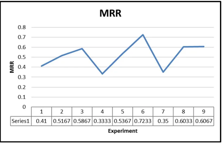
MATERIAL REMOVAL RATE (MRR):
The MRR is an important machining characteristics that determines the productivity in an industry. The MRR should be high to have better machining performance and to have high production rate. The MRR is calculated by using the following formulae,
MRR = (MRW/T) in g/min;
WRR = Work-piece removal rate in g; T = Machining time in minute;
S.NO Mass of the worpiece
before machining
g
Mass of the worpiece after
machining
g
Work-piece removal rate
WRR g
Machining time T minutes
Material removal rate
MRR g/minute
1 67.24 66.01 1.23 3 0.41 2 68.29 66.74 1.55 3 0.516667 3 64.33 62.57 1.76 3 0.586667 4 64.6 63.6 1 3 0.333333 5 70.91 69.3 1.61 3 0.536667 6 76.75 74.58 2.17 3 0.723333 7 67.02 65.97 1.05 3 0.35 8 69.4 67.59 1.81 3 0.603333 9 65.52 63.7 1.82 3 0.606667
Table 6-Material removal rate (MRR)
The table 6 shows the MRR value for all the nine experiments. And the graphical representation of the MRR is shown in the figure 5.
Fig.5-Material removal rate (MRR)
ELECTRODE WEAR RATIO:
Electrode wear imposes high costs on manufacturers to substitute the eroded complicated electrodes by new ones. In order to increase the machining efficiency, erosion of the electrode must be minimized in EDM process. Therefore, studying the electrode wear and related significant factors would be effective to enhance the machining productivity and process reliability. The electrode wear ratio (EWR) is defined by the ratio of the electrode wear weight (EWW) to the work piece removal weight (WRW) and usually expressed in percentage, that is
Where;
EWW = Electrode Wear Weight WRW = Work Piece Removal Weight
S.NO Mass of the
electrode before machining
g
Mass of the electrode after
machining
g
Electrode Wear weight EWW
g
Work-piece removal
weight WRW
g
Electrode wear ratio
EWR %
1 14.48 13.96 0.52 1.23 42.27642 2 14.73 14.32 0.41 1.55 26.45161 3 14.61 14.43 0.18 1.76 10.22727
4 14.71 14.41 0.3 1 30
5 14.48 14.31 0.17 1.61 10.55901 6 14.77 14.68 0.09 2.17 4.147465 7 14.6 14.47 0.13 1.05 12.38095 8 14.51 14.45 0.06 1.81 3.314917 9 14.56 14.52 0.04 1.82 2.197802
Table 7-Electrode wear ratio (EWR)
The table 7 shows the EWR value for all the nine experiments. And the graphical representation of the EWR is shown in the figure 6.
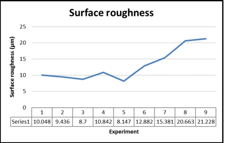
SURFACE ROUGHNESS:
The surface roughness of a machined material is also an important machining characteristics. The surface roughness is quantified by the deviations in the direction of the normal vector of a real surface from its ideal form. The surface is said to be rough for larger deviations and the surface is said to be smooth for smaller deviations. For better machining performance, the surface roughness value should be as low as possible.
S.NO PULSE ON
TIME µs
PULSEOFF TIME
µs
GAP VOLTAGE
V
PEAK CURRENT
A
ROUGHNESS VALUE
µm
1 50 4 100 35 10.048
2 50 8 120 37 9.436
3 50 12 130 40 8.700
4 100 4 120 40 10.842
5 100 8 130 35 8.147
6 100 12 100 37 12.882
7 200 4 130 37 15.381
8 200 8 100 40 20.663
9 200 12 120 35 21.228
Table 8-Surface roughness
The surface roughness value is found for all the experiments and the values are tabulated as in the table 8. The graphical representation of surface roughness is shown in the figure 7.
V. CONCLUSION
This study was carried out to optimize the EDM process on EN8 using copper as electrode. The conclusion of this study is summarized as follows,
1) The experiment 6 gives the most optimum machining characteristics with the MRR value of 0.72333 g/min, EWR value of 4.14747% and surface roughness value of 12.882µm.
2) The optimum machining parameters (experiment 6) are pulse on time is 100 µs, pulse off time is 12µs, gap voltage is 100V and peak current is 37A.
3) MRR increases with the increase in pulse on time and pulse off time. So, for higher MRR, the duration of pulse on time and pulse off time should be high.
4) EWR decreases with the increase in pulse on time and pulse off time. So, for lower EWR, the duration of pulse on time and pulse off time should be high.
5) Surface roughness increases with the increase in pulse on time and peak current. And surface roughness decreases with the increase in gap voltage. So, for lower surface roughness, gap voltage should be as high as possible and both pulse on time and peak current should be as low as possible.
REFERENCES
[1] Sengottuvel.P, Satishkumar.S, Dinakaran.D, “Optimization Of Multiple Characteristics Of EDM Parameters Based On Desirability Approach And Fuzzy Modeling”, International Conference On DESIGN AND MANUFACTURING, IConDM 2013, p. 1069 – 1078.
[2] I. Ayesta, B. Izquierdo, J.A. Sánchez, J.M. Ramos, S. Plaza, I. Pombo, N. Ortega, H. Bravo, R. Fradejas, I. Zamakona, “Influence of EDM parameters on slot machining in C1023 aeronautical alloy”, The Seventeenth CIRP Conference on Electro Physical and Chemical Machining (ISEM), p. 129 – 134.
[3] E. Uhlmann, D. C. Domingos, “Development and optimization of the die-sinking EDM-technology
for machining the nickel-based alloy MAR-M247 for turbine components”, The Seventeenth CIRP Conference on Electro Physical and Chemical Machining (ISEM), p. 180 – 185.
[4] Chinmaya P Mohanty, Siba Shankar Mahapatra, Manas Ranjan Singh, “An Experimental Investigation of Machinability of Inconel 718 in Electrical Discharge Machining”, 3rd International Conference on Materials Processing and Characterisation (ICMPC 2014), p. 605 – 611. [5] R. Roth, F. Kuster, K. Wegener, “Influence of oxidizing gas on the stability of dry electrical discharge machining process”, The Seventeenth
CIRP Conference on Electro Physical and Chemical Machining (ISEM), p. 338 – 343.
[6] S. Skoczypiec, K. Furyk, A. Ruszaj, “Computer simulation and experimental study of a sequential electrochemical - electrodischarge machining process.”, The Seventeenth CIRP Conference on Electro Physical and Chemical Machining (ISEM), p. 444 – 449.
[7] Rajiv kumar.N, Karthikeyan.S, Matheswaran.M.M, “MULTI-OBJECTIVE OPTIMIZATION OF SPARK EDM PROCESS PARAMETERS FOR INCONEL 800”, International Journal of Modern Trends in Engineering and Science.
[8] N.Rajiv Kumar, K.P.Shankar, P.Umar Ahamed, “Analysis of the influence of EDM process parameters on surface quality, MRR, EWR FOR EN31”, International Journal of Latest Engineering and Management Research (IJLEMR), Volume 1 - Issue 7, p.01-09.
[9] S Ahmad and M A Lajis, “Electrical discharge machining (EDM) of Inconel 718 by using copper electrode at higher peak current and pulse duration”, Materials Science and Engineering 50 (2013) 012062.
[10] Reman, Vineet Singla, “Comparison of Different Electrodes Used in EDM for En31 Work Piece”, International Journal of Enhanced Research in Science Technology & Engineering, Vol. 3 Issue 8, August-2014, p.192-200.