Multi-Mode Factor for Cantilevered Structures with Variable Mass and Stiffness
Dennis NiehoffProject Engineer, Savannah River, Savannah, GA ([email protected])
Orhan Gürbüz
Fellow and Senior Principal Engineer, Bechtel national, Inc., Huntington Beach, CA 92649 ([email protected])
ABSTRACT
In the design of nuclear safety-related structures, dynamic analyses are routinely carried out to develop in-structure response spectra (ISRS). The ISRS are then used for determining the seismic forces for the design of systems and components. For this purpose, either a dynamic analysis is carried out with the ISRS as the input or an equivalent static analysis is performed with accelerations obtained from the ISRS. In the latter case, there are two options available: the fundamental frequency of the subsystem can be calculated and the corresponding spectral acceleration is applied or simply the peak of the spectral acceleration is selected. In either case a question arises as to the contribution of the higher modes to the total response. NUREG 0800 (Section 3.7.2) requires that a factor of 1.5 be applied to the peak of spectra, although lesser values may be used with justification. Similarly, ASCE 4-98 also requires the use of 1.5 times the peak spectral acceleration.
The basis of the multi-mode factor of 1.5 appears to be the paper by Stevenson and Lapay which was the recommended multi-mode factor for uniformly loaded multi-span beams. Lower values were recommended for beams with concentrated loads or single span beams. A later study by Czarnecki on uniform cantilevers showed that the multi-mode factor is closer to unity. Nevertheless, the practice of using a multi-mode factor of 1.5 for both cantilever as well as single and multiple span beams with concentrated or uniform loads has continued to date.
The purpose of this study is to analytically determine a more appropriate multi-mode factor for cantilevers with variable stiffness and mass.
INTRODUCTION
In nuclear safety related structures, primary structures are first analyzed to determine the in structure response spectra (ISRS) at key points. In general, these primary structures are also analyzed using time-histories or response spectra to determine the member seismic forces for design. Standards used for the analysis of nuclear structures, systems, and components (SSC) allow the use of an equivalent static load method. When the equivalent static methods are used, both NUREG 0-800 [1] and ASCE 4 [2] suggest determination of the equivalent-static loads as the product of the masses of the systems (structure, equipment, and supported commodities) multiplied by an acceleration equal to 1.5 times the peak acceleration of the applicable response spectrum. The factor 1.5 represents the effect of higher modes and has been termed “equivalent-static load factor (ESLF)” or “multi-mode factor” or “amplification factor” by various investigators. In this paper these terms are used interchangeably.
The seminal study on the equivalent static method of analysis [3] concluded that factors ranging from 1.0 to 1.5 are appropriate to account for the higher mode effects. Parametric studies were carried out on cantilevers as well as simply supported beams (both single and multi-spans) to determine a conservative amplification factor. The commodity considered in these studies was piping. The value of 1.0 was recommended for a concentrated load in single or multiple spans. At the other extreme, the value of 1.5 was found to be appropriate for uniformly loaded multiple span beams.
The URS/Blume [4] study considered cantilevers with uniform mass and stiffness. Four different types of cantilevers, (1) rigid, (2) bending mode shape, (3) straight line mode shape, and (4) parabolic mode shape, were considered. Results showed that for a first mode approximation, a factor of 1.0 or less for shear and 1.04 or less for moment was appropriate.
This study furthers the URS/Blume study by considering beam-stick models of cantilevers with five or ten nodes and with variable mass and stiffness. Variations included linearly increasing or decreasing mass and stiffness, concentration of mass near the base or near the free end (inverted pendulum) and with mass concentrated at mid-height of the structure. These variations were intended to cover the spectrum of cantilever structures and components one could reasonably expect. Analyses were performed using an EXCEL spreadsheet, to compute the eigenvalues, mode shapes, and participation factors. Seismic response was then calculated using constant accelerations to isolate the multi-mode effects. The modal mass was also calculated to develop insight into the mass associated with each mode.
The results for base shear show that the multi-mode factor is equal to or less than 1.0 in all cases. In the case of the moment, the factor depends on the vertical distribution of the mass and stiffness. It is shown that the dynamic factor is primarily a function of the characteristic mode shapes and not the combination of modes. For the worst case assumption of all modes excited at the peak spectral response value, the maximum dynamic increase factor is about 1.2 for base moment. Based on these findings, it is proposed to revise the provisions of ASCE 4 so that more realistic design forces can be obtained for design.
CASES STUDIED
Cantilever structures, including bottom-supported components that might be encountered in nuclear facilities, may have variable stiffness and/or mass along its height. Thus, a parametric study was deemed essential to determine multi-mode factors that would be applicable to a wide range of cantilever structures or components. Based on the evaluation of cantilever beams of various types, it was noted that the “shear beam” resulted in the largest base overturning moment. Hence, this evaluation was based on various distributions of mass and stiffness of a cantilevered shear beam.
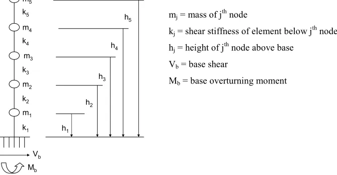
The basic model consisted of a 5 node cantilevered beam model as shown in Figure 1. Both the masses and stiffnesses were varied along the height of the model in an effort to envelop the possible distributions that might be encountered for based-mounted equipment in a critical facility. The mass was assumed to vary linearly form top to bottom and to either bulge or pinch at the mid height. In addition, models with concentrated masses at the bottom and at the top (an inverted pendulum) were also studied. To insure that the mass and stiffness variations included a practical range, the masses were varied up to a factor of five and the stiffnesses were varied up to a factor of four. Furthermore, the basic model of uniform mass and stiffness properties was refined as a ten node model to study the effect of model refinement. Initially 11 mass/stiffness distributions were analyzed having the properties as shown in Table 1.
V b M
b m
5
m 4
m 3
m 2
m 1 k
5
k 4
k 3
k 2
k1 h
1 h
2 h
3 h
4 h
5 mj = mass of j
th
node
kj = shear stiffness of element below j th
node hj = height of jth node above base
Vb = base shear
Mb = base overturning moment
Figure 1. Basic Model Used in Analyses and the Associated Nomenclature
Table 1. Cantilever Beams Included the Parametric Study
Relative Masses Relative Stiffnesses Case
No. Ma
ss
S
tif
fn
e
ss
m1 m2 m3 m4 m5 k1 k2 k3 k4 k5
1.
1 1 1 1 1 1 1 1 1 1
2.
1 2 3 4 5 1 1 1 1 1
3.
1 2 3 2 1 1 1 1 1 1
4.
5 4 3 2 1 1 1 1 1 1
5.
3 2 1 2 3 1 1 1 1 1
6.
9.3
(70%) 1 1 1 1 1 1 1 1 1
7.
1 1 1 1 (70%)9.3 1 1 1 1 1
8.
1 1 1 1 1 2 2 1 1 1
9.
1 1 1 1 1 2 2 2 1 1
10.
1 1 1 1 1 2 2 2 2 1
11.
1 1 1 1 1 0.25 1 1 1 1
12.
10.5
(72.5%) 1 1 1 1 1 1 1 1 1
Each model was analyzed dynamically to determine the base shear and overturning moment. Since all five modes are considered in the calculations, the dynamic analyses results (modal responses) are precise. For modal combinations, both the absolute sum and the square-root-of-the-sum-of-the-squares (SRSS) were considered. For dynamic response determination, a spectrum with constant acceleration was assumed. Using a constant acceleration is equivalent to assuming the same peak acceleration for all frequencies of the system. This is a conservative approximation since the actual spectra consist of a peak (usually between 1 to 10 Hz in the horizontal direction), followed by a decrease in accelerations until the rigid range is reached. Even after broadening according to ASCE 4, the peak of a typical spectrum is narrow and not all the frequencies of a system would fall on the peak.
For the equivalent static case, which is considered the baseline, the base shear is calculated by multiplying the total mass with the same constant acceleration and the overturning moment is total mass times the acceleration times the distance to the mass center. The ESLF is then calculated as the ratios of base shear and overturning moments obtained from dynamic and static analyses.
After the initial cases were run, the mass/stiffness configuration with a large mass near the base was determined to result in the maximum equivalent dynamic factor for base reactions. By progressive changes in the mass assumed at the base, the highest factor was obtained.
The study reported in this paper deals only with the horizontal responses of cantilevered structures and components. In the vertical direction these structures are typically rigid and the question of an ESLF does not arise.
METHOD OF APPROACH
The equations of motion for a lumped mass cantilevered system can be written as [M] {d2x/dt2} + [C] {dx/dt} + [K] {x} = {m} d2z/dt2
where {x}, {dx/dt}, {d2x/dt2} are the displacement, velocity, and acceleration vectors d2z/dt2 is the ground acceleration
[M] is the mass matrix [C] is the damping matrix [K] is the stiffness matrix
For the case of free undamped vibration, a general solution to the differential equations of motion can be written as {x} = {Φ} eiωt
{d2x/dt2} = -ω2 {Φ} eiωt
Substituting for x in the undamped free vibration equation of motion gives -ω2 [M] {Φ} eiωt + [K] {Φ} eiωt = 0
The nontrivial solution will then take the form ([K] – ω2 [M]) {Φ} = 0 or
([K]-1[M] – 1/ω2) {Φ} = 0 (which is the form of the characteristic or eigenvalue equation) where 1/ω2 are the eigenvalues of [K]-1[M]
{Φ} are the eigenvectors or mode shapes
Substituting the generalized coordinates ({x} = {Φ} u) into the equations of motion equation allows the solution to be obtained by independent single degree of freedom representations and then combining the results:
[M]Φ(d2u/dt2) + [C]Φ(du/dt) + [K]Φ(u) = {m}(d2z/dt2) Pre multiplying by ΦT (the transpose of the Φ matrix)
ΦT[M]Φ(d2u/dt2) + ΦT[C]Φ(du/dt) + ΦT[K]Φ(u) = ΦT{m}(d2z/dt2) Dividing by ΦT [M] Φ gives
(d2u/dt2) + (ΦT[C]Φ/ΦT[M]Φ)(du/dt) + (ΦT[K]Φ/ΦT[M]Φ)(u) = (ΦT{m}/ΦT[M]Φ)(d2z/dt2)
The factor multiplying the base acceleration on the right side of the equation is referred to as the participation factor, Γ Γ = ΦT{m}/ΦT[M]Φ
Utilizing the available response spectra associated with the base of the structure or component modeled as a cantilever, the node response in each mode can be calculated from the relationship
d2x/dt2 =Γ Φ Sa
where d2x/dt2 is the nodal acceleration in the mode being evaluated Γ is the mode participation factor
Φ is the eigenvector of characteristic shape for the mode (mode shape) Sa is the spectral acceleration at the mode frequency
Using the relationship of force equals the mass multiplied by acceleration, the force at each node for the particular mode under consideration is given by
F = m Γ Φ Sa
To isolate the effect of multimode participation and provide the bounding results, the spectral acceleration was assumed as constant and equal to the maximum value over the entire frequency range. The base shear can then be calculated in each mode as the sum of the individual node forces (f), including the algebraic sign. The base overturning moment was calculated in a similar manner by multiplying the node force by the height of node above the base.
Two methods of combining the individual modal responses of base shear and overturning moment were considered, 1) square root of the sum of the squares (SRSS) and 2) absolute sum.
To further shed light on the results, the modal mass (ΦT {m} Γ) and its percentage of total mass were calculated. Also the effective modal center of gravity, calculated as the mode base overturning moment divided by the mode base shear. This modal center of gravity was compared to the center of gravity of the mass of the cantilever lumped mass model and expressed as a modal multiplier. The Equivalent Static Base Shear Factor is calculated as the ratio of the combined base shear for all of the modes divided by the total of all the node masses multiplied by Sa. The Equivalent Static Base Moment Factor is
calculated, in a similar way, as the ratio of the combined base moment for all of the modes divided by the sum of the node masses multiplied by their corresponding height and by Sa
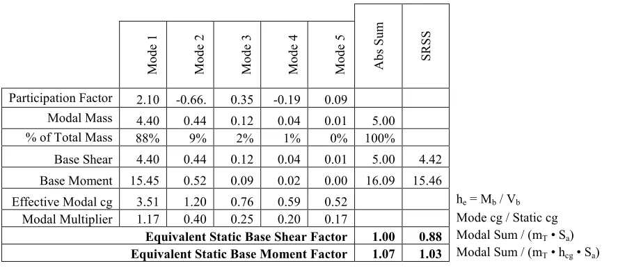
For this investigation a series of EXCEL spreadsheets were developed utilizing a five (5) degree of freedom cantilever model. The responses due to each mode were combined by both absolute sum and the square root of the sum of the squares methods. Table 2 shows a summary of the results obtained for a uniform mass and stiffness cantilever beam.
Table 2. Modal Analysis Results with Constant Spectral Acceleration
M o d e 1 M o d e 2 M o d e 3 M o d e 4 M o d e 5 A b s S u m S R S S
Participation Factor 2.10 -0.66. 0.35 -0.19 0.09 Modal Mass 4.40 0.44 0.12 0.04 0.01 5.00
% of Total Mass 88% 9% 2% 1% 0% 100%
Base Shear 4.40 0.44 0.12 0.04 0.01 5.00 4.42 Base Moment 15.45 0.52 0.09 0.02 0.00 16.09 15.46
Effective Modal cg 3.51 1.20 0.76 0.59 0.52 he = Mb / Vb
Modal Multiplier 1.17 0.40 0.25 0.20 0.17 Mode cg / Static cg Equivalent Static Base Shear Factor 1.00 0.88 Modal Sum / (mT • Sa)
Equivalent Static Base Moment Factor 1.07 1.03 Modal Sum / (mT • hcg • Sa)
RESULTS
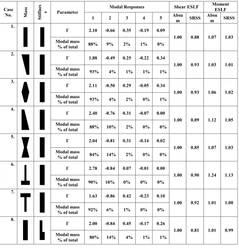
The results of parametric studies show that the ESLF for base shear is always 1.0 if the absolute sum option is used. This is reasonable since the base shear is equal to modal mass times the spectral acceleration summed over all the modes. In this study a constant spectral acceleration was used; therefore, the result always adds to unity. If the SRSS method is used, then the base shear ESLF will be less than unity, simply because SRSS of several numbers which add up to one will be less than one. Both ESLFs for base shear are shown in Table 3.
Table 3. Modal Responses and Shear and Moment Amplification Factors
Modal Responses Shear ESLF Moment
ESLF Case
No. Ma
ss
S
tif
fn
e
s
s Parameter
1 2 3 4 5 Absu
m SRSS Absu
m SRSS
Г 2.10 -0.66 0.35 -0.19 0.09 1.
Modal mass
% of total 88% 9% 2% 1% 0%
1.00 0.88 1.07 1.03
Г 1.88 -0.49 0.25 -0.22 0.34 2.
Modal mass
% of total 93% 4% 1% 1% 1%
1.00 0.93 1.03 1.01
Г 2.11 -0.50 0.29 -0.05 0.34 3.
Modal mass
% of total 93% 4% 2% 0% 1%
1.00 0.93 1.06 1.02
Г 2.40 -0.76 0.31 -0.07 0.00 4.
Modal mass
% of total 88% 10% 2% 0% 0%
1.00 0.89 1.12 1.05
Г 2.04 -0.81 0.31 -0.14 0.02 5.
Modal mass
% of total 84% 14% 2% 0% 0%
1.00 0.85 1.07 1.03
Г 2.78 -0.84 0.07 -0.01 0.00 6.
Modal mass
% of total 90% 10% 0% 0% 0%
1.00 0.90 1.24 1.13
Г 1.63 -0.86 0.42 -0.23 0.10 7.
Modal mass
% of total 92% 6% 1% 0% 0%
1.00 0.92 1.01 1.00
Г 2.00 -0.84 0.45 -0.17 0.26 8.
Modal mass
% of total 80% 14% 4% 1% 1%
1.00 0.81 1.01 0.99
Г 2.03 -0.79 0.32 -0.33 0.16 9.
Modal mass
% of total 83% 13% 2% 2% 1%
1.00 0.84 1.02 1.00
Г 2.08 -0.65 0.42 -0.25 0.11 10.
Modal mass
% of total 87% 8% 4% 1% 0%
1.00 0.87 1.05 1.03
Г 2.21 -0.32 0.10 -0.04 0.02 11.
Modal mass
% of total 98% 2% 0% 0% 0%
1.00 0.98 1.09 1.05
Г 2.81 -0.83 0.06 -0.01 0.00 12.
Modal mass
% of total 91% 9% 0% 0% 0%
1.00 0.92 1.25 1.13
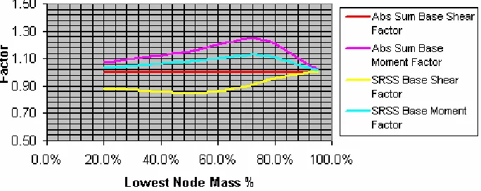
In the case of the overturning moment, the ESLF is generally greater than one. Again, the absolute sum procedure results in higher factors than the SRSS method. Review of the results indicate that the multi-mode factor is higher for the structures whose mass is reduced with height. The highest factor was given by case 6. A number of additional cases were added to the study, iterating on the mass assigned to the lowest node in an effort to identify the maximum moment factor that could be expected. This iteration resulted in a maximum ESLF when 72.5% of the mass was assigned to the lowest node and is shown as case 12 in the two tables above. A graph of the results of this investigation is provided in Figure 2. The maximum factor is obtained when a large mass exists at the base and the mass at the higher elevations are lower. This may be termed “whipping effect” of the higher stories; the lesser masses above the base are driven by the base mass and causes the increased ESLF. The maximum ESLF thus determined is 1.2. Again, the ESLFs for the overturning moments are included in Table 3.
Figure 2, Base Factor as a Function of Percentage of Mass Near the Base
SUMMARY AND CONCLUSIONS
Provisions have been made in a number of standards used for the analysis of safety related components for a simplified method of determining seismic base shear and moment. With the recent advent in design philosophy of insuring ductile anchorage, the former practice of specifying very conservative loads to guard against non ductile failure is not necessary and potentially excessively costly. With this as a basis, it is appropriate that the simplified and, therefore conservative, methodologies used in the past be reconsidered. This study has evaluated a subset, but a significantly large subset, of safety related cantilevered substructures or components that require anchorage in nuclear facilities. Cantilevered structures and components have been analyzed for a wide range of variable masses and stiffnesses to determine appropriate
equivalent static load factors (ESLF) for seismic loads. The analyses included an equivalent-static analysis where the seismic loads were approximated by multiplying the mass of the structure by acceleration equal to the peak of the response spectrum. The cantilever structure or component was also analyzed by the response spectrum method. By comparing the base shear and overturning moment results from these analyses, equivalent static load factors were determined.
This study has confirmed that the use of a ESLF of 1.5 in conjunction with the peak spectral acceleration is extremely conservative for cantilever structures and components. In general it is understood that the SRSS method of combination of individual modal response is appropriate for the lower frequency modes with absolute sum more appropriate for the higher frequency modes. As can be seen by a review of the modal mass associated with the cantilevered configurations considered in this study the vast majority of response is associated with the first two modes. Therefore, the factor derived by SRSS combination is the more appropriate one to be used. The study has led to the following conclusions:
1. The ESLF for base shear should be calculated using a factor of 1.0 for all cantilever structures and components. 2. For the overturning moment, a ESLF of 1.2 is adequate for all cantilever structures and components.
It should be recognized that the study is based on constant spectral accelerations. Real in-structure response spectra (ISRS), will have peaks over a narrow range of frequency and thus the modal accelerations outside the peak range will be lower. Consequently, the conclusions reached above are conservative, since the total dynamic response for any cantilever structure or component subjected to a realistic ISRS, will be lower than the values that will be obtained following the recommendations of this paper.
Lastly, analysis using a refined model of the basic cantilever (10 nodes) has shown that the results obtained with the five-mass model resulted in no significant change in the calculated factors and, therefore, no additional refined analyses are necessary to confirm the recommendations of this paper.
REFERENCES
1. NUREG 0800 (1986), Review of Safety Analysis Reports for Nuclear Power Plants, Rev. 2
2. American Society of Civil Engineers. (1998), “Seismic Analysis of Safety-Related Nuclear Structures,” Reston, Virginia.
3. Stevenson, J. D. and W. S. Lapay (1974), “Amplification Factors to be used in Simplified Seismic Dynamic Analysis of Piping System,” Proceedings, American Society of Mechanical Engineers, 1974
4. Czarnecki, R. M., et al, (1991). “Justification for a Static Coefficient of 1.0,” in Seismic Verification of Nuclear Plant Equipment Anchorage, EPRI NP-5228-SL, Revision 1, Volume 1.