ISSN(Online): 2319-8753 ISSN (Print): 2347-6710
I
nternational
J
ournal of
I
nnovative
R
esearch in
S
cience,
E
ngineering and
T
echnology
(A High Impact Factor & UGC Approved Journal) Website: www.ijirset.com
Vol. 6, Issue 8, August 2017
Implementation of a Reliable Anti-Collision
Technique for RFID Using 1-To-4 RFRJ
Coding
K.Poojit Avinash1, R.Gurunadha2 M.Tech Student, JNTUK-UCEV, AP, India1
Assistant Professor, Dept. of ECE, JNTUK-UCEV, AP, India2
ABSTRACT: While transmitting secret data over Internet or by any other means our whole concern is to make it secure before transmission so that it should not be disclosed to pirates. In this paper, a novel coding based on the RANDOM FLIPPING AND RANDOM JAMMING (RFRJ), has been proposed for Secure Communication of Secret Information. In this proposed approach the secret information is transformed and then the shares of the transformed information are generated. These shares are then transmitted individually. RCEAT ARCHITECTURE is used, which consists of the preRCEAT and postRCEAT methods for the construction of information shares & reconstruction of secret information from the information shares resulting the scheme with very low computational complexity and highly secured. Experimental results show that this scheme is simple and effective.
The PreRCEAT subsystem is to detect any error in the incoming messages. Then the identification bit (ID) of the no error packet will be fed to the next subsystem.
The PostRCEAT subsystem is to identify the tag by using the proposed Fast-search Lookup Table. The proposed system is designed using Verilog HDL. Finally the RCEAT architecture is synthesized using xillins 14.5.
KEYWORDS: RFID, Pseudo Random Number, Secret Sharing, Secret Communication, RFRJ, RCEAT, PreRCEAT, PostRCEAT
I. INTRODUCTION
ISSN(Online): 2319-8753 ISSN (Print): 2347-6710
I
nternational
J
ournal of
I
nnovative
R
esearch in
S
cience,
E
ngineering and
T
echnology
(A High Impact Factor & UGC Approved Journal) Website: www.ijirset.com
Vol. 6, Issue 8, August 2017
Further to boom the extent of safety, before generation of the stocks, the authors have transformed enormously mystery image based on a mystery pseudo random collection and this transformation procedure additionally has a completely low computational complexity. Thus standard computational complexity remains very low and secret photograph becomes distinctly secured even with out the use of any traditional cryptography or steganography schemes.
Cryptographic hash capabilities that are typically nonlinear capabilities have been broadly used in lots of cryptographic structures. These hash capabilities have many facts safety programs, appreciably in digital signatures, message authentication codes (MACs), and other varieties of authentication. They also can be used as ordinary hash functions, to index information in hash tables, for fingerprinting, to come across replica information or uniquely perceive files, and as checksums to come across unintentional information corruption.
II.PRELIMINARIES
Secret Sharing:
Secret Sharing refers to a way for dispensing a secret among a group of members. Each of whom is allocated a percentage of the name of the game. The mystery may be reconstructed best whilst a sufficient range of shares are blended collectively: Individual stocks are of no need on their very own.
Distributed RFID Systems
In the traditional RFID system, an RF reader has two components, a transmitter (i.e., query transmission/energizingtags) and a listener (i.e., listening to a tag’s reply) as shownin Fig. 1a, where a diamond represents the transmission function of a reader, a circle represents the listening function of a reader, and a rectangle represents a tag. The communication range of the backward channel is much shorterthan that of the forward channel, and thus readers must bedeployed based on the short-range backward channel to access all tags in the region as shown in Fig.2.1a. A recentstudy proposes Distributed RF Sensing model thatemploys two kinds of devices (a single RF transmitter and anumber of RF listeners) for each function of a reader as shown in Fig 4.1b. The model contributes to cost reduction of RFID system deployment For example, in Fig.4.1b, the traditional RFID system requires nine transmitters and nine listeners, while the distributed RFID system requires one transmitter and nine listeners.
Fig.2.1 Distributed RFID systems.
ISSN(Online): 2319-8753 ISSN (Print): 2347-6710
I
nternational
J
ournal of
I
nnovative
R
esearch in
S
cience,
E
ngineering and
T
echnology
(A High Impact Factor & UGC Approved Journal) Website: www.ijirset.com
Vol. 6, Issue 8, August 2017
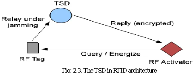
TSD architecture
Fig. 2.3. The TSD in RFID architecture
An RF reader is divided into two components,an RF activator and atrusted shield device (TSD). In our new architecture, an RF activator queries a tag with a long-rangesignal (i.e., the forward channel) and energizes the tag. A TSD receives a tag’s reply with a short-range signal (i.e., thebackward channel), and it sends the reply to the activatorvia an encrypted channel, which we define asthe relay channel. In typical RFID applications, a reader forwards tags data to the back-end server. For simplicity, in this paper weconsider the RF activator as the final destination of a tag’s data by assuming the activator forwards collected data tothe back-end server. A TSD works as an RF listener and it is capable of bit level jamming during reception of a tag’sreply. Therefore, our new RFID system architecture consists of three components: an RF activator, a TSD, and RF tags.In this paper, we introduce a new coding scheme, namelyrandom flipping random jamming, for the backward channel protection. A tag will send encoded data (i.e., pseudoIDs) to a TSD under the jamming environment. This prevents adversaries from passive attacks, i.e., the random guessing attacks, correlation attacks, and eavesdropping.As we will show later, the RFRJ coding scheme ensures that adversaries cannot decode the original tag’s ID from incomplete data due to jamming while the TSD successfully recovers the data from imperfect information.A TSD is conceptually similar to the trusted masking device and a medical device shield implemented, but different in the following functions. On overhearing a query from an activator to a tag, aTSD jams a bit in a codeword. As mentioned in the assumption, bit level jamming is possible. If an unauthorized reader tries to access a tag, a TSD jams against all bits of codewords so that the unauthorized reader cannot read the content of the transmitted data. A similar function is implemented, where a shield device jams the whole communication on detecting unauthorized accesses. This canbe done by letting an authorized activator communicate with a TSD before a singulation process.Unlike the trusted masking device and medicalshield, a TSD intermediates only the backward channel.
III. RFRJ (RANDOM FLIPPING RANDOM JAMMING) ARCHITECTURE
ISSN(Online): 2319-8753 ISSN (Print): 2347-6710
I
nternational
J
ournal of
I
nnovative
R
esearch in
S
cience,
E
ngineering and
T
echnology
(A High Impact Factor & UGC Approved Journal) Website: www.ijirset.com
Vol. 6, Issue 8, August 2017
TABLE-3.1 Definition of the notations.
Symbols Definition
R The RF Activator r
S The TSD s
T The RF tag t
B The bit b
B The source bits {b1, b2, ….}
C The codeword c
C A domain of codewords C={c0 , c1, …..}
lc The length of a codeword |c|
lb The length of source bits |B|
I The index of a bit in a codeword
E(.) The function E:{0,1}lb ˿ {0,1}lc D(.) The function D:{0,1}lc ˿ {0,1}lb
H(b, bʹ) The Hamming distance between b and bʹ
H(b, bʹ , i) The Hamming distance between b and bʹ after removing the Ith bit of b and bʹ
Pj The probability that a jammed bits is flipped
Private Tag Access Protocol
The proposed private tag access protocol works as follows. Suppose an RF activator rplans to read an RF tagt without disclosing the tag’s ID to an eavesdropper. In this section, we first consider the length of the encoding unit lb to
be 1. Our idea can be applied to arbitrary values of lb and lc, where lb<lc. On receiving a request, the tag text ends bit
into an lc-bit codeword, where lc 4 must hold. When the tag transmits data over the backward channel, it randomly
selects a bit in a codeword and intentionally flips it. Note that this process is done before the tag sends out the codeword,so the data sent by the tag always contains a one-bit error. On the other hand, the TSD, which is an RF listener with jamming capability,jams a single bit in the codeword. The jamming causes the selected bit to flip. Let pj (0
pj 1) be the probability that the bit jammed by the TSD is flipped. We denote is and it as the indexes of the
selected bits by the TSD and the tag, respectively. The TSD randomly selects anybit in the first half of the lcbits codeword, i.e.,1 Is [1/2lc], while a tag randomly selects a bit in thesecond half of the codeword, i.e., [1/2lc]+1 It
ISSN(Online): 2319-8753 ISSN (Print): 2347-6710
I
nternational
J
ournal of
I
nnovative
R
esearch in
S
cience,
E
ngineering and
T
echnology
(A High Impact Factor & UGC Approved Journal) Website: www.ijirset.com
Vol. 6, Issue 8, August 2017
Fig.3. 2. The system model and basic idea
The Single Bit RFRJ Coding Scheme
The RFRJ coding scheme with the parameter lb =1 and lc =4. Note that lc =3 does not work and lc =4 is the most efficient in terms of communication cost, whichwill be shown later. Let b be a source bit and c be a codeword. The encoding function E(.):
{
0
,
1
}
{
0
,
1
}
4is defined by E(b)=c0 if b=0 and E(b)=c1 if b=1.The encoding function E(.) must ensure thatthe Hamming distance betweenc 0 and c1, denoted by H(c0;c1),is four. There are 16 such (c0;c1) pairs that can be used for private tag access. We call them valid 4-bit codeword pairs.Definition 1 (Valid 4-bit codeword pairs).
Whenlc =4,a codeword pair (c0;c1), corresponding to a source bit pair (0;1), is said to be valid when the Hamming distance betweenc 0and c1is four, i.e.
(0000,1111), (0001,1110), (0010,0101), (0100,1011), (1000,0111), (0011,1100), (0110,1001), (0101,1010), (C1,C0).
The 1-to-4 RFRJ Coding Scheme
We have illustrated how the RFRJ coding scheme encodes asingle source bit to a 4-bit codeword. In general, an RF taghas data with arbitrary length or a constant length ID (e.g.,96-bit defined in EPC Class1 Gen2 ). In this section, we elaborate on the complete 1-to-4 RFRJ coding scheme.In real RFID applications, a tag is likely to transmit thesame data, such as its ID, to a TSD several times. Should an eavesdropper continuously listen, it can recover the content of the tag response by the help of the previous interrogations (the correlation attack). To avoid the attack, we incorporate dependency by using different valid codeword pairs to each source bit.Let bk be the kth source bit that a tag
intends to encode.To encode bk, our coding scheme employs the previous source bits,bk-1, bk-2, bk-3, and bk-4. To be
specific, we use the coding table in Table 3.3, where bk=0 if k<=0.For example, the source bits with length our,1010,
willbe encoded into four codewords with each having 4 bits,i.e.,1111 0011 1110 1001.The decoding process is basically the same, but uses different codeword pairs for each source bit. The corresponding codeword for the bkth
ISSN(Online): 2319-8753 ISSN (Print): 2347-6710
I
nternational
J
ournal of
I
nnovative
R
esearch in
S
cience,
E
ngineering and
T
echnology
(A High Impact Factor & UGC Approved Journal) Website: www.ijirset.com
Vol. 6, Issue 8, August 2017
TABLE-3.3 Coding Rule for the 1-to-4 RFRJ Coding Scheme
bk-4bk-3bk-2bk-1
bk=0
c
bk=1
c|
0000 0000 1111
0001 0011 1100
0010 0001 1110
0100 0101 1010
0101 1001 0110
0110 1000 0111
0111 1011 0100
1000 1111 0000
1001 1100 0011
1010 1110 0001
1011 0010 1101
1100 1010 0101
1101 0110 1001
1110 0111 1000
1111 0100 1011
SECURITYANALYSIS
In this section, we provide security analysis for the proposed coding scheme. Every source bit is assumed to be 0or 1 with the same probability 0.5.
The 1-to-4 Coding Security
Let X be a random variable that represents the number of flipped bits in a codeword. The Itth bit selected by a
tag is always flipped with the probability 1, since this is done before the data is transmitted. On the other hand, theist bit selected by a reader is flipped with the probability pj,since the jamming does not guarantee that a target bit isflipped.
In RFRJ, 1 or 2 bits in a codeword could be flipped depending on pj. The probability that the events X=1and X=2 occur
is obtained by
X
Pj
P
1
1
(3.1)
X
Pi
P
2
(3.2)Since X is either 1or2,P[X=1]+P[X=2]=1.Inour 1-to-4 RFRJ coding scheme, an eavesdropper cannot decodewhen 2 bits are flipped. Thus, the eavesdropper cannot decode the source bit with the probability pj. This rule is only applied to
the first source bit, but not to the kth bit for k>1 because it is encoded with a dependency.Let Xk be a random variable
that represents the number of flipped bits in the codeword corresponding to the kth source bit. Again Xk could be 1 or 2.
Since a valid codeword pair used for the kth source bit is defined by the previous sourcebits, an eavesdropper must decode the [k1]th source bit to successfully decode the kth source bit. Thus, the probability that the eavesdropper can decode the kth source bit is P[Xk=1|Xk1=1] with the base P[X0=1]=1. Although the selection of a valid codeword pair is
dependent, Xk=1,2 and Xk1=1,2 are independent events.
K j K K K Kp
X
P
X
P
X
P
X
X
P
)
1
(
]
1
[
]
1
[
].
1
[
1
|
1
1 1
(3.3)
ISSN(Online): 2319-8753 ISSN (Print): 2347-6710
I
nternational
J
ournal of
I
nnovative
R
esearch in
S
cience,
E
ngineering and
T
echnology
(A High Impact Factor & UGC Approved Journal) Website: www.ijirset.com
Vol. 6, Issue 8, August 2017
4.5 Random Guessing Attacks
When the eavesdropper cannot decode, they may guess the source bit to be either 0 or 1 with even probability (i.e., the random guessing attacks). In this subsection, we consider the security of our coding scheme against an eavesdropper with random guessing capability. When a bit flipping by jamming fails, the eavesdropper decodes with the probability 1. Otherwise, it can successfully decode with the probability 0.5 by random guessing. Let b| be the bit decoded bythe eavesdropper. Thus, the probability that the eavesdropper successfully decodes the source bitbis given by:
].
2
[
2
1
]
1
[
]
[
b
b
P
X
P
X
P
(3.4)Let bk and bk1be the kth source bit and a bit decoded by the eavesdropper, respectively. We can obtain the probability
that the random guessing succeeds at the kth source bitas follows:
K j K K K K K K K K K K K
p
X
P
X
P
b
b
P
X
P
X
P
b
b
X
P
b
b
X
P
b
b
P
)
2
1
1
(
])
2
[
2
1
]
1
[
(
]
[
])..
2
[
2
1
]
1
[
(
]
|
2
[
2
1
]
|
1
[
]
[
1 1 1 1 1 1
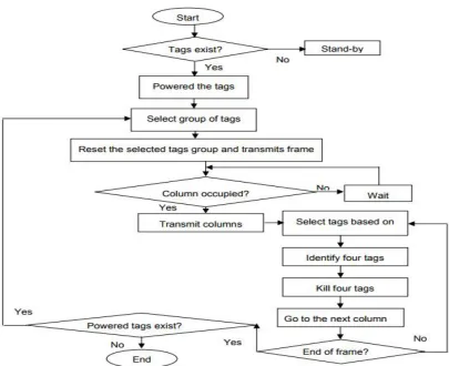
(3.5)IV.ANTI-COLLISION TECHNIQUE FOR RFID UHF TAG
We are implementing Reliable and Cost Effective Anti-collision technique (RCEAT).In our RCEAT the body consists of slots and each slot (column) is split into 4 minislots (rows). Therefore in each slot, 4 tags are allowed for contending the minislots. The RCEAT will discover these four tags the use of the proposed Lookup desk. The strong point of this proposed method is reducing the tag identity time in the Binary Tree. The present tags are divided into 4 in every Read cycle to lessen the desired iterations and for that reason quicker the tag identity. This proposed technique does no longer require the tag to recollect the commands from the reader for the duration of the identification technique. Thus the tag is treated as an address wearing device best and reminiscence-less tag may be designed which calls for very low strength. In RCEAT, bidirectional communications are concerned, from the reader to the tag (Downlink) and from the tag to the reader (Uplink). When the reader detects there are tags exist in its interrogation sector, it's going to strength these tags. Then the reader sends the Select-institution command primarily based on the tag Prefix or Object Class (OC). The selected tags institution will flow to the Ready country. Next the Reader transmits Reset alerts and its body. After that the body is transmitted back to the reader, column by means of column beginning with the first column. This compensates the time required for transmitting the packet to the reader. Therefore for each Read cycle, there are constantly available packets on the reader watching for identity.
ISSN(Online): 2319-8753 ISSN (Print): 2347-6710
I
nternational
J
ournal of
I
nnovative
R
esearch in
S
cience,
E
ngineering and
T
echnology
(A High Impact Factor & UGC Approved Journal) Website: www.ijirset.com
Vol. 6, Issue 8, August 2017
Fig.4.1 Individual tags linked with the frame.
ISSN(Online): 2319-8753 ISSN (Print): 2347-6710
I
nternational
J
ournal of
I
nnovative
R
esearch in
S
cience,
E
ngineering and
T
echnology
(A High Impact Factor & UGC Approved Journal) Website: www.ijirset.com
Vol. 6, Issue 8, August 2017
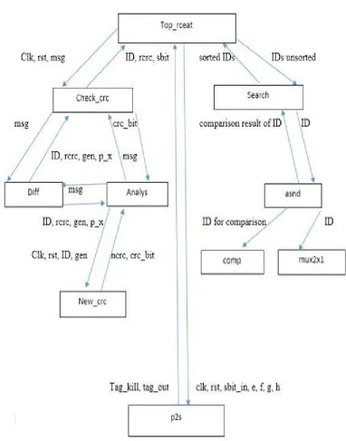
Implementation
ISSN(Online): 2319-8753 ISSN (Print): 2347-6710
I
nternational
J
ournal of
I
nnovative
R
esearch in
S
cience,
E
ngineering and
T
echnology
(A High Impact Factor & UGC Approved Journal) Website: www.ijirset.com
Vol. 6, Issue 8, August 2017
V.RESULTS
Results of RFRJ coding:
Fig 5.1 simulation results of RFRJ coding
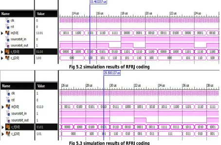
In the above fig 5.1 shows the simulation results of RFRJ coding. It consists of clk,rst,in[3:0],sourcebit_in,sourcebit_out,c_f[3:0],c_j[2:0]. Here in[3:0] indicates the input message which is to be transmitted. The sourcebit_in indicates that which codeword has to be generated when 0 or 1 is given. The sourcebit_out indicates which bit is flipped in the input message after the generaton of codeword. C_f[3:0] indicates the codeword after flipping the bit. C_j[2:0] indiactes the output after jamming the first bit.
Fig 5.2 simulation results of RFRJ coding
ISSN(Online): 2319-8753 ISSN (Print): 2347-6710
I
nternational
J
ournal of
I
nnovative
R
esearch in
S
cience,
E
ngineering and
T
echnology
(A High Impact Factor & UGC Approved Journal) Website: www.ijirset.com
Vol. 6, Issue 8, August 2017
Results of RCEAT:
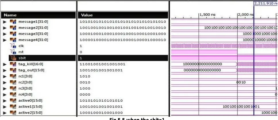
Fig 5.4 when the sbit=0
In the above fig 5.4 we can see the simulation results of the RCEAT. The input includes four 32-bit messages:
ISSN(Online): 2319-8753 ISSN (Print): 2347-6710
I
nternational
J
ournal of
I
nnovative
R
esearch in
S
cience,
E
ngineering and
T
echnology
(A High Impact Factor & UGC Approved Journal) Website: www.ijirset.com
Vol. 6, Issue 8, August 2017
If the tag_kill=1, then it means that the incoming message from the p2s module does have an error in it. The status bit sbit=1 indicates that the crc and the new_crc are not equal. Hence, there is an error in the incoming messages.
VI. CONCLUSION
The primary goal of this project is to present an efficient preventive collision technique that has a small area, is cost efficient, and has low power consumption. The preventive collision method shown here consists of two subsystems. The first subsystem is PreRCEAT that uses the cyclic redundancy check approach to find if the incoming packets have any error. The second subsystem, PostRCEAT, identifies the packets that do not contain any errors and give the serial output with the use of the parallel to serial approach. The algorithm for the preventive collision technique is synthesized using Xilinx ISE.
The device utilization summary shows that the number of slice flip-flops used is only 4% of the total available flip flops, and the four input LUTs used are only 4% of the total available LUTs. These outcomes demonstrate that the proposed architecture requires a small cell area and uses fewer gates. The time analysis results show that the minimum time needed for input is 21.849ns, and the maximum output time required is 7.244ns. As a result, the implementation and operating costs will be minimized.
VII. FUTURE SCOPE
The active architecture can be implemented on hardware to overcome problems in real life scenarios such as in metro stations and bus transportation. In these situations, a number of passengers with unique ID cards will be able to check-in simultaneously on a single available RFID, thus saving time during the check-in process. Other improvements can be obtained through the use of high-end tools such as Cadence Virtuoso, to calculate the exact area (in nm2) required by the proposed architecture.
REFERENCES
[1] Y. Li and X. Ding, “Protecting RFID communications in supply chains,” inProc. 2nd ACM Symp. Inf., Comput. Commun. Security, 2007, pp. 234–241.
[2] H. K. H. Chow, K. L. Choy, W. B. Lee, and K. C. Lau, “Design of a RFID case-based resource management system for warehouse operations,”Expert Syst. Appl., vol. 30, no. 4, pp. 561–576, Feb. 2006.
[3] A. Juels,“RFID security and privacy: A research survey,” IEEE J. Sel. Areas Commun., vol. 24, no. 2, pp. 381–394, 2006.
[4] W. Choi, M. Yoon, and B.-h. Roh, “Backward channel protection based on randomized tree-walking algorithm and its analysis for securing RFID tag information and privacy,”IEICE Trans., vol. 91-B, no. 1, pp. 172–182, 2008.
[5] T.-L. Lim, T. Li, and S.-L. Yeo, “Randomized bit encoding for stronger backward channel protection in RFID systems,” in Proc. IEEE 6th Annu. Int. Conf. Pervasive Comput. Commun., 2008, pp. 40–49.
[6] K. Sakai, W.-S. Ku, R. Zimmermann, and M.-T. Sun, “Dynamic bit encoding for privacy protection against correlation attacks in RFID backward channel,”IEEE Trans. Comput., vol. 62, no. 1, pp. 112–123, Jan. 2013.
[7] L. Sang, “Designing physical primitives for secure communication in wireless sensor networks,” Ph.D. dissertation, Department of Computer Science and Engineering, The Ohio State University, 2010.
[8] M. Jain, J. L. Choi, T. M. Kim, D. Bharadia, S. Seth, K. Srinivasan, P. Levis, S. Katti, and P. Sinha, “Practical, real-time, full duplex wireless,” inProc. 17th Annu. Int. Conf. Mobile Comput. Netw., 2011, pp. 301–312.
[9] A. D. Wyner,“The wire-tap channel,” Bell Syst Tech. J., vol. 54,no. 8, pp. 1355–1387, 1975.
[10] S. Gollakota, H. Hassanieh, B. Ransford, D. Katabi, and K. Fu, “They can hear your heartbeats: Non-invasive security for implantable medical devices,” inProc. ACM SIGCOMM Conf., 2011, pp. 2–13.
[11] H. Delfs and H. Knebl,Introduction to Cryptography: Principles and applications, 2nd ed. New York, NY, USA: Springer, 2007.
[12] Barcodes Inc. (2014, Feb.). Choosing the Right RFID Technology. [Online]. Available: https: //www.barcodesinc.com/info/buying-guides/rfid.htm.
[13] S. Smiley (2016, Mar. 4). UHF RFID Passive vs. Active. [Online]. Available:http://blog.atlas rfidstore.com/active-rfid-vs-passive-rfid#disqus_thread.
[14] C. M. Roberts, “Radio frequency identification (RFID),” Computers & Security, vol. 25, no.1, pp. 18-26, 2006. [15] J. Myung, W. Lee, and J. Srivastava, “Adaptive binary splitting for efficient RFID
ISSN(Online): 2319-8753 ISSN (Print): 2347-6710
I
nternational
J
ournal of
I
nnovative
R
esearch in
S
cience,
E
ngineering and
T
echnology
(A High Impact Factor & UGC Approved Journal) Website: www.ijirset.com
Vol. 6, Issue 8, August 2017
[16] P. Pupunwiwat, “Tag anti-collision resolution for improved quality of RFID data streams,” Ph.D. dissertation, School of Informat. Commun. Tech., Griffith University, Brisbane, Australia, 2011.
[17] C. Law, K. Lee, and K. Y. Siu, “Efficient memoryless protocol for tag Identification,”
in Proc. 4th International Workshop on Discrete Algorithms and Methods for Mobile Computing and Communications, Aug 2000, vol. 7, pp. 75-84.
[18] J. Ryu, H. Lee, Y. Seok, T. Kwon, and Y. Choi, “A hybrid Query Tree protocol for tag collision arbitration in RFID systems,” in Proc. IEEE Int. Conf. Communications (ICC), 2007, vol. 7 pp. 5981-5986.
[19] L. Liu, and S. Lai, “ALOHA-based anti-collision algorithms used in RFID system,”
in Proc. International Conference on Wireless Communications, Networking and MobileComputing, September 2006, pp. 1-4.
[20] J. Sampe, K. P. Zakaria, F. H. Hashim, and M. Othman, “Reliable and cost effective anti collision technique for RFID UHF tag,” in Proc. 4th International Conference on IEEEModeling, Simulation and Applied Optimization, April 2011, pp. 1-5.
[20] C. Borrelli (2001, Mar.). IEEE 802.3 Cyclic Redundancy Check. [Online]. Available: http: //www. xilinx.com /support /documentation /application_notes /xapp209. pdf.
[21] Verilog Inc. (2012). Verilog Resources. [Online]. Available: http://www.verilog.com