Computer Aided Manufacturing of Titanium
(Grade 5) Alloy Part
Kolhe Pravin R.*1, Lande Shantanu S.*2, Bahalkar Sarang S.*3, Bhanushali Himanshu S.*4, Patil Amit S.*5 Department of Mechanical Engineering, MET’S IOE, Bhujbal Knowledge City, Nashik, Maharashtra, India*12345
ABSTRACT: Ti-6Al-4V is the most popular material in Automobile, Aerospace and Biomedical Engineering due to its inherent properties like high strength at elevated temperature, grate corrosion resistance, dimensional stability at various environment etc. It quite difficult to machining because low modules of elasticity, Hardening during machining etc. This paper gives experiment investigation about cutting tool stress on titanium alloy grade 5 at various cooling strategy with measuring surface quality in application of CAM strategy.
KEYWORDS: Lubrication Strategy, Surface Finish, Surface integrity, Ti-6Al-4V alloy, CAM Strategies.
I. INTRODUCTION
Titanium and its alloys used extensively in aerospace of their excellent combination of high specific strength to weight ratio, which is maintained at elevated temperature, their fracture resistance characteristics and their exceptional resistance to corrosion [1]. The Ti-6Al-4V (α-β) offer high toughness, superb corrosion & creep -resistance, bio-capability [2]. It shows useful performance at temperatures up to about 600oc & 60% lighter than general steel. Titanium is very chemically reactive and therefore, has a tendency to weld to the cutting tool during machining, thus leading to chipping and premature tool failure [3].
Despite the increased usages and production of titanium alloys, they are expensive when compared to many other metals because of complexity of the extraction process, difficulty of melting and problems that “Machinability of titanium and its alloys” would always be problematic. & matter about techniques are employed to transform this metal into chips” The poor Machinability of titanium and its alloys have lead many large companies (E.g. Rolls-Royce, GE, HAL, India) to invest large sums of money in the developing techniques to minimize machining cost. Reasonable production rates & excellent surface quality can be achieved with non-conventional machining method if the unique characteristics of the metal of its alloys are taken into account.We work on Ti-6Al-4V machining by using Unigraphics 8.00 CAM Software & Widea tooling to the optimum satisfied level of Ti- machining with a study of cooling techniques, CAM Strategy and cutting tool stress. This helps to introduce new way of machining of challengeable material like Ti alloys.
According to Nambia Muthukrishnan application of coolant tends to reduce tool wear and gives a good surface finish compared with dry machining and tool life is improved by 30% .Adhesive wear is observed at the flank portion of the insert on both dry and wet machining. Diffusion wear is more in dry machining [6]. As per Adriano Fagali de Souza Milling is the most important machining process in this industry. Even using updated technologies such as High Speed Milling, which improves the machined surface quality, the hand finishing is still required and it brings some drawbacks such as costs, time and geometrical errors. Today, any CAM software offers some different tool path strategies to milling free form geometries. However, the users must have the know-how to choose the strategies according to geometry complexity, cutting tool geometry and its contact on the machined surface. Choosing an optimum strategy is a rather difficult task to do on the shop floor. The path strategy influences real machining time, polishing time and costs. The results show that the right choice of the tool path can save 88% of the time and 40% of the costs for finishing the mold evaluated, if compared to the less appropriate option [7].
Patil Amit S. has study the various machining problem discussed by different researchers and their probable solution, which helps to reduce tool wear, high surface finish with effective lubrication strategy by reducing machining complexity. The conclusion presented is Lubrication system influences tool life, surface finish and metallurgy of work piece. Cryogenic lubrication with high pressure through spindle gives a segmentation of chip and avoid thermal gradient of cutting tool tip, high pressure easily flown out the chips from cutting area as a result greater surface finish and tool life. Surface finish is directly depends upon machining conditions. Good surface finish obtained at minimum depth of cut, maximum R.P.M., with low cutting speed in wet machining. Dry machining should be avoided for saving tool life and surface texture [8].
II. CAM STRATEGY
According to Ramos et al. the adequate choice of a tool path to milling a specific geometry can propitiate a reduction of the production costs and improve the surface roughness. [9]. Besides, the tool path can influence the real machining time due to the amount of acceleration and deceleration involved, and direction alteration of the movements on the machine [10]. Any commercial CAM software today offers several possibilities of the strategies of distributing the tool path in the domain of the designed part. The commonly used tool path distribution strategies are [11-12].
The following strategies are used in UG NX 8.00 CAM for Milling.
Strategy No 1: Floor wall and Rest Milling-
Floor Wall - It is basically 2D dimensional machining strategies generally using for flat machining it consists of follow cut pattern at 13mm step over at constant radial depth. Tool path are parallel to each other.
Rest Milling - It is used for removing the material live by the previous method of milling at 3D profile. Fig no.1 shows rest milling tool path in follow cut pattern with 4mm step over. In this way the combination of the above strategy utilizes in pilot experimentation
Strategy No 2: Cavity milling-
It is a 3D milling Strategy for finishing extruded core portion or variable geometrical complexity cavity parts. In this experiment cavity mill strategy applies to non-steep portion of cavity shown in fig no 1. Tool path lines in flow cut pattern at 10 mm step over are applying for the machine
Strategy No 3: Contour Area–
Strategy No 4: Stream line –
This Strategy uses flow and cross geometrix and software created tool path flow the combination of this geometrix along with directrix this Strategy recommends for complex shape at control the flow and direction of the smooth control pattern here we used 10 mm step over with flow cut pattern under restricted boundary shown in fig no 1. This strategy is strictly three dimensional geometrix.
Strategy No 5: Cavity –Trochoidal Milling + Contour area non Steep-
It is a basically cavity milling Strategy with trochoidal cut pattern at 10 mm step over. Trochoidal milling efficient way to produce 2D or 3D dimensional slot at the bottom surface in this Strategy cutting tool path constant interpolation movement in the direction of providing directrix fig no 1. But this method not suitable for radial curve surfaces at the z-level, it creates a trade mark at z-level vertical wall to remove this we make combination with counter area non steep. We are applying this Strategy with boundary drive method at a constant radial depth of cut in an outward pattern direction (Tool cut the material and movies outward in a radial direction from cutting zone at the end of cutting tool path) Here there is no dwell in feeding. The cutting tool path is connected to the each other as shown in fig no.1. We are using 10 mm steep over throughout this Strategy.
Fig. 1: Cavity Trochoidal, Contour, Steam, Rest Milling Strategies
III. LUBRICATION STRATEGIES
Lubrication strategies are important at the time of machining on Ti-6Al-4V hard material. Coolant is used for the reduction in heat produced between tool and work piece at the time of machining and it is an important factor for the reduce tool wear and gives a good surface finish. Lubrication and cooling strategies for titanium machining operations are areas where the cutting process can be improved. The low thermal conductivity of Ti6Al4V causes a concentration of the heat build-up in the cutting zone [9]. At high tool temperatures, typically above 550 ºC, the heat transfer mechanism between the cooling fluid and the tool surface changes to two phase high-speed flow For optimizing the result we used various lubrication strategies are Dry, 5% coolant, 10% coolant, 15% coolant and Liquid Nitrogen (LN2).
3.1. Dry lubrication strategy - The jet of air fired through an appropriate spindle, or nozzle, creates a fine atomized layer of air-oil mixture that, on reaching the cutting surface, enables efficient lubrication of the machining process. At the time of dry lubrication strategies heat and friction between tool and material (Ti-6Al-4V) is highly generated and tool wear is more it reduced tool life. This strategy hasn’t given a good surface finish. Fig no.2 shows a dry machining on Ti-6Al-4V material.
3.2. 5% lubrication strategy-
Fig. 2: Dry, 10%, Liquid Nitrogen lubrication strategies
3.4. 15% lubrication strategy -
In this strategy the density of oil in water increased by 15%. This strategy gives a good surface finish compared to previous strategies. Heat generates between tool and Ti-6Al-4V material is low and tool wear is less and it increased tool life. It reduced machining time and increased production rate.
3.5. Liquid Nitrogen (LN2) Strategy -
In this strategy we used liquid nitrogen as a coolant whose temperature is -194 0C. Liquid nitrogen is a colorless clear liquid with a density of 0.807 g/ml. Liquid Nitrogen also called as Cryogenic Machining. Cryogenic machining has several advantages over conventional coolants. LN2 is allowed to evaporate near the cutting edge of insulated tools, it
promotes the dissipation of heat, which otherwise would soften tools and accelerate wear.
Some benefits of LN2 cooling are as follows:
Sustainable manufacturing (cleaner, safer and environmentally friendly), Increased material removal rate,
Increased tool life and surface quality/integrity as compared to other cooling media.
IV. DOE FOR CAM STRATEGIES
Design of experiment is used for minimizing the number of experiments for finding out optimum output of providing input during this experiment we used 6 factor and their five different levels for observing the effect on surface quality with respect to generated stress on cutting tool. This DOE helps to find out the relation between stress and surface finish. The following table gives details about DOE.
Table 1: DOE for CAM Strategies
Tri al No.
RPM Vc
m/ min
Feed (mm)
DO C
Coo lant
Tool C A M
1 318 20 76.43 0.1 Dry THR 1 2 557.32 20 76.43 0.2 5% THM 2 3 318.47 20 76.43 0.3 10
%
HK200 0
3
4 318.47 20 76.43 0.4 15 %
PA120 4
5 318.47 20 76.43 0.5 LN2 TN450 5
6 398.09 25 87.58 0.2 10 %
7 398.09 25 87.58 0.3 15 %
TN450 1
8 398.09 25 87.58 0.4 LN2 THR 2
9 605.10 25 87.58 0.5 Dry THM 3 10 398.09 25 87.58 0.1 5% HK200
0 4
11 636.94 30 95.54 0.3 LN2 THM 4
12 477.71 30 95.54 0.4 Dry HK200 0
5
13 477.71 30 95.54 0.5 5% PA120 1 14 477.71 30 95.54 0.1 10
%
TN450 2
15 477.71 30 95.54 0.2 15 %
THR 3
16 557.32 35 100.32 0.4 5% TN450 3 17 557.32 35 100.32 0.5 10
%
THR 4
18 668.79 35 100.32 0.1 15 %
THM 5
19 557.32 35 100.32 0.2 LN2 HK200
0 1
20 557.32 35 100.32 0.3 Dry PA120 2 21 636.94 40 101.91 0.5 15
%
HK200 0
2
22 636.94 40 101.91 0.1 LN2 PA120 3
23 636.94 40 101.91 0.2 Dry TN450 4 24 636.94 40 101.91 0.3 5% THR 5 25 716.56 40 101.91 0.4 10
%
THM 1
V. EXPERIMENTAL SETUP AND PROCEDURE
For the experimental verification of Roughness value, we are use following free-form model shown in Fig.3.
All cases investigated were machined by 3 Axes Vertical Milling Center - MAKINO S56. The analysis of surface roughness on the basis of cusp height by using -Mahr surface tester.
Procedure- The proposed work investigates the efficiency of the different tool path strategy for finishing milling of complex geometries, usually faced in the mold industries. To do so, a mold containing a representative work piece was designed and manufactured for this project. The mold part having 5 cavities designed symmetrically in Fig.3. Due to its symmetrical complexity, this geometry propitiates a possible way to investigate the manufacturing process of a plastic product. The 5 cavities were roughened in the same manner, by 3 axis milling, leaving a uniform amount of material of 0.2 mm, to be removed by the finishing on milling, which was the focus of this study. Each of the 5 cavities was finished by a different tool path strategy. The CAM software UG NX 8 from SIMENSE was used to calculate the tool path under the tolerance zone of 0.01 mm.
VI. STRESS Vs. SURFACE ROUGHNESS (Ra) CURVE
Calculation-
Average chip thickness (hm):
………(mm)
Where, Dc = Cutter diameter (mm) ae = Width of cut (mm)
kr = Entering angle of cutting tool = 90°
Cutting Force (kc):
………. (N/mm2) Where, Kc1 = Cutting force for 1 mm chip thickness (N/mm2),
kc1 = 1450 (N/mm2)………. For Titanium alloys
mc = Exponent
= 0.23………….For Titanium alloys hm = Average chip thickness (mm)
= Effective rake angle
………( )
N/mm2
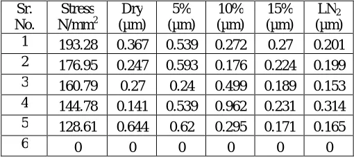
Table 2: Stress and Surface roughness at various cooling media
Sr. No.
Stress N/mm2
Dry (µm)
5% (µm)
10% (µm)
15% (µm)
LN2
(µm) 1 193.28 0.367 0.539 0.272 0.27 0.201 2 176.95 0.247 0.593 0.176 0.224 0.199 3 160.79 0.27 0.24 0.499 0.189 0.153 4 144.78 0.141 0.539 0.962 0.231 0.314 5 128.61 0.644 0.62 0.295 0.171 0.165
Above graph plotted Surface roughness (µm) Vs. Stress (N/mm2) shows following remarkable point:
1. In the presence of Dry air as a cooling media, then stress at cutting insert is high and it produces a poor surface finish.
2. In the presence of 5% emulsion in the coolant, then stress at cutting insert is high, but it produces a good surface finish.
3. In the presence of 10% emulsion in the coolant, stress at cutting insert is high. The pick point in the 10% curve shows the poorest surface roughness due to tool brake at this point.
4. In the presence of 15% emulsion in the coolant, stress at cutting insert is relatively low and but it produces a good surface finish as compared to first three cooling media.
5. In the presence of liquid nitrogen as cooling media, then stress at cutting insert is same as that but it produces an excellent surface finish as compared to other cooling media. In the graph low pick point shows a good surface roughness at the presence of liquid nitrogen as a coolant.
From above discussed point we conclude that “When stress at cutting insert is increases, then surface quality is decreases.”
VII. CONCLUSION
The presented experimental evaluation of CAM strategies with various lubrication strategies gives following valuable decision
1. The surface roughness value decreases with increases the percentage of emulsion fluid.
2. Stress on cutting tool is minimum then the Ra value is decreases but co-ordinally depends upon CAM strategy and metal removing parameters.
3. Cryogenic machining gives better machining effect with Titanium alloy grade 5 with respect to surface quality, cutting stress.
4. Vc (mm/Min) most dominate metal cutting parameter on surface quality in presence of cooling effect.
5. The Counter area milling strategy gives the best surface quality in effect of cooling techniques.
6. Coolant is a most dominate factor for decreasing cutting stresses at cutting edge portion of cutting tool as a result better surface finish.
REFERANCES
[1] A.R. Machado,J Wallbank. “Machining of titanium and its alloys-a review,” Journal of Engineering Man. Proc. Inatn. Mech. Engrs.Vol.204. [2] Durul Ulutan, Tugrul Ozel, “Machining induced surface integrity in titanium and nickel alloys: A review,” International Journal of Machine Tools & Manufacture, 2011, vol. 51, pp. 250–280.
[3] L. Zhou, J. Shimizu, A,Muroya and H. Eda. “Material Removal Mechanism beyond Plastic Wave Propagation Rate,” Precision Engineering, 2003, Vol. 27, No. 2, pp. 109-116. doi:10.1016/S0141-6359(02)00124-1
[4] C.T. Olofson, F.W. Boulger, J.A. Gurklis “Machining And Grinding of Titanium And Its Alloy,” Nasa Technical Memorandum X-53312, 1965, pp. 5-26.
[6]. Nambia Muthukrishnan, Paulo Davim, “Influence of Coolant In Machinability of Titanium Alloy” Journal of Surface Engineered Materials and Advanced Technology, 2011, 1, 9-14
[7] Adriano Fagali de Souza,Adriane Machado, Sueli Fischer Beckert, Anselmo Eduardo Diniz “Evaluating the roughness according to the tool path strategy when milling free form surfaces for mold application” 6th CIRP International Conference on High Performance Cutting, HPC 2014, Procedia CIRP 14 ( 2014 ) 188 – 193.
[8] Patil Amit S., Ingle Sushil V., More Yogesh S., Nathe Manik S. “Machining Challenges in Ti-6Al-4V.-A Review,” International Journal of Innovations in Engineering and Technology (IJIET) Volume 5 Issue 4 August 2015 ISSN: 2319 – 1058.
[9] Ramos M, Relvas C, Simoes JA. The Influence of Finish Milling Strategies on Texture, Roughness and Dimensional Deviation on the Machining of Complex Surfaces. Journal of Materials Processing Technology; 2003, 136.
[10] Monreal M, Rodriguez, CA. Influence of Tool Path Strategy on Cycle Time of High-Speed Milling. Computer-aided Design; 200335.
[11] Choi YK. Tool Path Generation and 3D Tolerance Analysis for Free-Form Surfaces. Submitted To Texas A&M University In Partial Fulfillment of The Requirements For The Degree of Doctor of Philosophy; 2004.