ISSN(Online): 2319-8753 ISSN (Print): 2347-6710
I
nternational
J
ournal of
I
nnovative
R
esearch in
S
cience,
E
ngineering and
T
echnology
(A High Impact Factor, Monthly, Peer Reviewed Journal)
Visit: www.ijirset.com
Vol. 6, Issue 10, October 2017
FLC Based Standalone Wind Energy
Conversion System for DC Base Telecom
Loads
Dasanam Shireesha1,B.Anusha2, Maloth Chandra Sekhar Naik3
Assistant Professor, Dept of EEE, CMRCET, Hyderabad, India1
M.Tech Scholar, Dept of EEE, CMRCET, Hyderabad, India2
M.Tech Scholar, IASC, Bangalore, India3
ABSTRACT: The main demand for renewable energy resources is increase in the price and limited availability of conventional energy resources. Available alternative sources of wind energy are neat and clean but due to the intermittent nature it can need back up. In order to ascertain continuous supply of potency felicitous storage technology is utilized as backup. In this paper, the sustainability of a 4-kW hybrid of wind and battery system is investigated for meeting the requisites of a 3-kW stand-alone dc load representing a base telecom station. A charge controller of battery bank charging and discharging depends on Fuzzy logic controller predicated maximum power point tracking and battery state of charge. The mechanical safety and electrical safety of wind energy conversion system is achieved by using pitch control technique. Both the control schemes are integrated and the efficacy is validated by testing it with various load and wind profiles in MATLAB/SIMULINK.
KEYWORDS: Maximum Power Point Tracking (MPPT), Pitch Control, State Of Charge (SOC), Wind Energy Conversion System (WECS).
I. INTRODUCTION
ISSN(Online): 2319-8753 ISSN (Print): 2347-6710
I
nternational
J
ournal of
I
nnovative
R
esearch in
S
cience,
E
ngineering and
T
echnology
(A High Impact Factor, Monthly, Peer Reviewed Journal)
Visit: www.ijirset.com
Vol. 6, Issue 10, October 2017
II. HYBRID WIND-BATTERY SYSTEM FOR AN ISOLATED DCLOAD
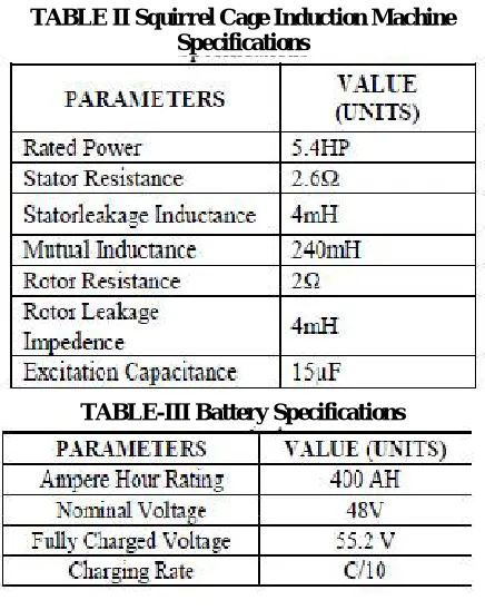
The hybrid wind-battery system consists of 4-KW WECS and 400 Ah , C/10 lead acid battery bank. The system is considered for a 3-KW stand-alone dc load. The layout of the entire system is shown in fig.1.The specifications of the WT, Self Exited induction Generator (SEIG), and battery bank are tabulated in the Appendix.The components of wind energy system is 4.2-kW, horizontal axis wind turbine, gear box with a gear ratio of 1:8 and a 5.4 hp SEIG as the wind Turbine Generator(WTG). Since the load is a stand-alone dc load the stator terminals of the SEIG are connected to a capacitor bank for self-excitation. The ac output is rectified by three-phase uncontrolled diode rectifier. However, there is a need for a battery backup to meet the load demand during the period of unavailability of
sufficient wind power. This hybrid wind-battery system requires suitable control logic for interfacing with the load .The uncontrolled dc output of the rectifier is applied to the charge controller circuit of the battery. The charge controller is a dc–dc buck converter which determines the charging and discharging rate of the battery. The battery bank connected to the system can be act as source at the discharging mode of battery as well as while charging mode it can be act as load. However, apart from of this the battery ensures that the load terminal voltage is regulated.
ISSN(Online): 2319-8753 ISSN (Print): 2347-6710
I
nternational
J
ournal of
I
nnovative
R
esearch in
S
cience,
E
ngineering and
T
echnology
(A High Impact Factor, Monthly, Peer Reviewed Journal)
Visit: www.ijirset.com
Vol. 6, Issue 10, October 2017
III. CONTROL STRATEGY FOR STANDALONE HYBRIDWIND-BATTERY SYSTEM
The wind flow is not available constantly. That’s why we are using the control strategies in wind energy conversion system for getting the desired output in stand-alone control system. In this system AC-DC,DC-DC because of eliminated the voltage flickers and harmonics. The control scheme for a
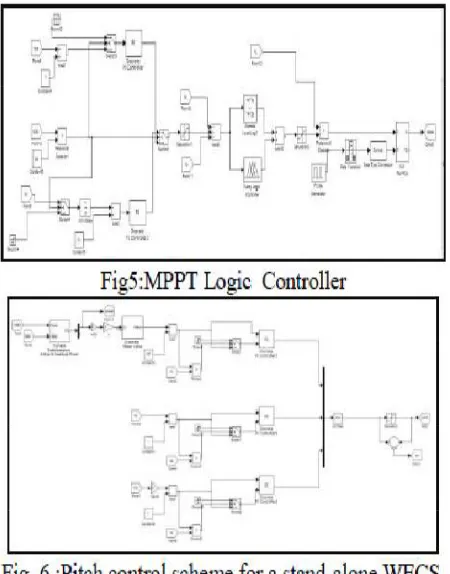
Fig.3: hybrid wind energy conversion system for dc base telecom station
stand-alone hybrid wind battery system includes the charge controller circuit for battery banks and pitch control logic to ensure WT operation within the rated value.
A. Charge Controller for the Battery Bank:
In MATLAB simulation we are using the 400 Ah, C/10 battery bank using a dc–dc buck converter. However, the current required for charging the battery bank depends on the battery State Of Charge. A typical battery generally charges at a constant current (CC), i.e., C/10 rate mode till battery SOC reaches a certain level (90%–98%). This is referred to as CC mode of battery charging. The CC mode charges the battery as fast as possible. Beyond this SOC, the battery is charged at a constant voltage (CV) which is denoted as CV mode of battery charging in order to maintain the battery terminal voltage.
B. Control Strategy:
The implementation of the charge control logic as shown in Fig. 2 is carried out by three nested control loops. The outer most control loop operates the turbine following MPPT logic with battery SOC limit it is clearly shown in fig3 and fig5. To implement the MPPT logic, the actual tip speed ratio (TSR) of turbine is compared with the optimum value The error is tuned by a PI controller to generate the battery current demand as long as the battery SOC is below the CC mode limit. Beyond this point, the SOC control logic tries to maintain constant battery charging voltage. This in turn reduces the battery current demand and thus prevents the battery bank from overcharging. The buck converter
inductor current command is generated in battery current (Ib) with respect to the inductor current(IL). The immediate
ISSN(Online): 2319-8753 ISSN (Print): 2347-6710
I
nternational
J
ournal of
I
nnovative
R
esearch in
S
cience,
E
ngineering and
T
echnology
(A High Impact Factor, Monthly, Peer Reviewed Journal)
Visit: www.ijirset.com
Vol. 6, Issue 10, October 2017
Fig. 4.Circuit representation of buck converter output. The transfer function can be computed from Fig. 4 and isgiven by
As shown in Fig. 4, the battery is assumed to be a CV source with a small internal resistance (rb). The Effective Series
Resistances(ESR) of the capacitor (rc) and the inductor (rL) are also considered. The ESR of the capacitor and the
inductor are taken to be 1mΩ each. The batteryinternal resistance is 10 mΩ.
ISSN(Online): 2319-8753 ISSN (Print): 2347-6710
I
nternational
J
ournal of
I
nnovative
R
esearch in
S
cience,
E
ngineering and
T
echnology
(A High Impact Factor, Monthly, Peer Reviewed Journal)
Visit: www.ijirset.com
Vol. 6, Issue 10, October 2017
system the frequency of this zero is 50 times lower than the crossover frequency. To improve the phase margin of the battery charging current control loop a lead compensator is connected in flow with the PI controller as shown in Fig. 2 The zero and pole of the lead compensator are designed to have a positive phase margin and to limit the crossover frequency to about 14% of the switching frequency. In order to check the over loading of turbine (and its consequent stalling) the lead compensator output is first passed through an adjustable current limiter. The lower limit is fixed to zero and the upper limit is changed according to the maximum power available at a given wind speed. it is shown in fig.5. The output of this limiter is used as the reference for the current controller in the dc–dc converter. Finally, in the inner most loop the actual inductor current is made to track the reference using peak current mode control. The compensated output of the intermediate loop is compared with the instantaneous inductor current of the buck converter. The output of the comparator is applied to an SR flip flop to generate the gate pulses for the dc–dc buck converter. The frequency of the clock pulses is 2 kHz. The frequency of the gate pulse is equal to the clock pulse frequency. The generating the clock pulses in this method is known as the current programmed control technique. Inductor current exceed the rated current at that time it can be passed through the buck converter for reducing the current. This happens because with increase in blade pitch the lift coefficient reduces which results in decreasing the value of CP. So, the pitch control mechanism controls the power output by reducing the power coefficient at higher wind speeds. Below the rated wind speed the blade pitch is maintained at zero degree to obtain maximum power. The pitch controller increases the blade pitch as the WT parameters exceed the rated value.
IV. MODES OF BATTERY CHARGING
In CC mode of Battery charging and CV mode of Battery charging already discussed in III.
Pitch Control Scheme:
The pitch control scheme is shown in Fig. 6 As seen the P.U value of each input is compared with 1 to calculate the error The errors are adjusted by PI controller. The “MAX” block chooses the maximum output from each PI controller which is then passed on to a limiter to generate the pitch command for the WT. The actual pitch command is compared with the limited value. The lower limit of the pitch command is set at zero. There arises an error when the actual pitch command goes above or below the specified limit. This is multiplied with the error obtained from each of the comparator. The product is compared with zero to determine the switching logic for integrator. This technique is carried out to avoid integrator saturation. The pitch controller changes the pitch command owing to variation in turbine rotation speed, power, and output voltage of rectifier, which ensures safe operation of the WECS.
V. FUZZY CONTROLLER
Fuzzy logic uses fuzzy set theory, in which a variable is member of one or more sets, with a specified degree of membership. Fuzzy logic allow us to emulate the human reasoning process in computers, quantify imprecise information, make decision based on vague and in complete data, yet by applying a “defuzzification” process,arrive at definite conclusions.
The FLC mainly consists of three blocks
Fuzzification Inference Defuzzification
RULES:
ISSN(Online): 2319-8753 ISSN (Print): 2347-6710
I
nternational
J
ournal of
I
nnovative
R
esearch in
S
cience,
E
ngineering and
T
echnology
(A High Impact Factor, Monthly, Peer Reviewed Journal)
Visit: www.ijirset.com
Vol. 6, Issue 10, October 2017
E = Error
CE = Change in Error
NB = Negative Big
NS = Negative small
ZE = Zero Error
PS = Positive Small
PB = Positive Big
VI. RESULTS AND DISCUSSIONS
The system is connected to a load profile varying in steps from 0 to 4 kw. The WT factors like shaft speed, TSR, blade pitch and output power are analyzed with variation in wind speed conditions. The current profile of the converter, load, and the battery are also supervised with the wind profile. To ensure continuous power flow, load demand is given more priority over battery charging. The WT and battery parameters are observed for the following wind profiles.
1. Gradual rise and fall in wind speed.-fig-7 2. Step variation in wind speed.-fig-8 3. Arbitrary variation in wind speed.-fig-9
ISSN(Online): 2319-8753 ISSN (Print): 2347-6710
I
nternational
J
ournal of
I
nnovative
R
esearch in
S
cience,
E
ngineering and
T
echnology
(A High Impact Factor, Monthly, Peer Reviewed Journal)
Visit: www.ijirset.com
Vol. 6, Issue 10, October 2017
ISSN(Online): 2319-8753 ISSN (Print): 2347-6710
I
nternational
J
ournal of
I
nnovative
R
esearch in
S
cience,
E
ngineering and
T
echnology
(A High Impact Factor, Monthly, Peer Reviewed Journal)
Visit: www.ijirset.com
ISSN(Online): 2319-8753 ISSN (Print): 2347-6710
I
nternational
J
ournal of
I
nnovative
R
esearch in
S
cience,
E
ngineering and
T
echnology
(A High Impact Factor, Monthly, Peer Reviewed Journal)
Visit: www.ijirset.com
Vol. 6, Issue 10, October 2017
Fig. 9. (a) WT and (b) battery parameters under the influence of step variation of wind speed.
VI. CONCLUSION
In this paper, a hybrid wind-battery system is selected to supply the desired load power. To moderate the random characteristics of wind flow the WECS is interfaced with the load by suitable controllers. The control logic put into practice in the hybrid set up includes the charge control of battery bank using MPPT and pitch control of the WT for assuring electrical and mechanical safety. The pitch control logic guarantee that the rectifier voltage does not lead to an overvoltage situation. The hybrid wind-battery system along with its control logic is employed in MATLAB/ SIMULINK and is tested with various wind profiles.
Appendix:
ISSN(Online): 2319-8753 ISSN (Print): 2347-6710
I
nternational
J
ournal of
I
nnovative
R
esearch in
S
cience,
E
ngineering and
T
echnology
(A High Impact Factor, Monthly, Peer Reviewed Journal)
Visit: www.ijirset.com
Vol. 6, Issue 10, October 2017
TABLE II Squirrel Cage Induction Machine Specifications
TABLE-III Battery Specifications
REFERENCES
[1]. A. D. Sahin, “Progress and recent trends in wind energy,” Progress in Energy Combustion Sci., vol. 30, no. 5, pp. 501–543, 2004. [2]. R. D. Richardson and G. M. Mcnerney, “Wind energy systems,” Proc. IEEE, vol. 81, no. 3, pp. 378–389, Mar. 1993.
[3]. R. Saidur, M. R. Islam, N. A. Rahim, and K. H. Solangi, “A review on global wind energy policy,” Renewable Sustainable Energy Rev., vol. 14,no. 7, pp. 1744–1762, Sep. 2010.
[4]. N. S. Hasan, M. Y. Hassan, M. S. Majid, and H. A. Rahman, “Review ofstorage schemes forwind energy systems,” Renewable Sustainable EnergyRev., vol. 21, pp. 237–247, May 2013.
[5]. A. M. D. Broe, S. Drouilhet, and V. Gevorgian, “A peak power tracker forsmall wind turbines in battery charging applications,” IEEE Trans. Energy convers., v vol. 14, no. 4, pp. 1630–1635, Dec.
1999.
[6]. R. Kot, M. Rolak, and M. Malinowski, “Comparison of maximum peakpower tracking algorithms for a small wind turbine,” Math.Comput.Simul., vol. 91, pp. 29–40, 2013.
[7]. M. Narayana, G. A. Putrus, M. Jovanovic, P. S. Leung, and S. McDonald,“Generic maximum power point tracking controller for small-scale windturbines,” Renewable Energy, vol. 44, pp. 72–79, Aug. 2012.
[8]. K. Y. Lo, Y. M. Chen, and Y. R. Chang, “MPPT battery charger for standalonewind power system,” IEEE Trans. Power Electron., vol. 26, no. 6,pp. 1631–1638, Jun. 2011.