PRESENTATION OF THE EVOLUTION OF THE RCC-M CODE IN THE 2016 & 2017 EDITIONS
Stéphane Marie1, Manuela Triay1, Eric Meister2, Etienne Bianquinch1, Emmanuel Chantelat3, Denis Pinier2, Francois Bogaert1, Philippe Malouines1
1
AREVA-NP, 92084 Paris la Défense, France 2
EDF SEPTEN, 69628 Villeurbanne, France 3
EDF CEIDRE, 93200 Saint-Denis, France
ABSTRACT
Important improvements are introduced in the last two editions of the AFCEN RCC-M code. Several technical working groups finalized or are finalizing their actions and provide to the RCC-M subcommittee significant technical proposals:
- New rules to assess the environmental effects in fatigue analyses for austenitic materials have been introduced as Rules in Probationary Phase (RPP);
- For welding, the specification of the ISO 3834 and the new ISO standard for operators and welders qualification has been introduced;
- A new appendix has been devoted to non-linear calculations, covering the finite elements calculation performance to the related criterion for the different failure mode assessed in the design rules;
- After several years of preparation, a new volume devoted to the functional qualification of active mechanical components, in consistency which the rules of the AFCEN RCC-E code for the electrical parts, has been introduced for pumps and valves;
- An update of the appendix has been on the bolted junctions.
This paper provides an overview of these technical changes and highlights their consequences for the users of the code.
1 INTRODUCTION
The AFCEN RCC-M code is devoted to the design and the fabrication of class 1, 2 and 3 nuclear pressurized equipment. Numerous working groups have been launched since four years to update the code.
Regarding evolutions to comply with French regulations, AFCEN decided in 2013 to launch several thematic working group, in order to answer the in close interface with the French Safety Authority. One major goal was to revise the appendixes ZZ and ZY in order to meet high expectation of the French Safety Authority to fulfill the essential safety requirements of the French Order of 12 December 2005 [1] related to nuclear pressure equipment (ESPN) and the Directive 97/23/EC [2] related to the pressure equipment (DEP). The result is updated appendixes ZZ and ZY of RCC-M code and additional professional guides to explain how to implement the above regulation. A first major evolution of these appendixes was introduced in the 2016 edition of the code. A final set of modification is planned for the 2018 edition, taking into account the change of the regulation with the European Directive 2014/68/UE for the PED and the new ESPN Order of December 30 2015.
In parallel of this first activity related to the French regulatory context, important technical evolutions of the RCC-M code have been introduced in the 2016 and 2017 editions of the code, or are still under preparation:
- For welding, the specification of the ISO 3834 and the new ISO standard for operators and welders qualification have been introduced;
- A new appendix devoted to non-linear calculations, covering the finite elements calculation performance to the related criterion for the different failure mode assessed in the design rules; - After several years of preparation, a new volume devoted to the functional qualification of active
mechanical components, in consistency which the rules of the AFCEN RCC-E code for the electrical parts, has been introduced for pumps and valves;
- An update of the appendix on the bolted junctions.
This paper focuses on these technical evolutions which aimed to answer to the needs of the code users. Concerning the specific developments linked to the French regulatory context, refer to references [15] and [16].
2 2016 EDITION MAIN IMPROVEMENTS
A complete list of the modification of this edition can be found in the paper [15]. Environmental effects in fatigue
Two Rules in Probationary Phase (RPP) were introduced in the edition 2016 [6] to modify the fatigue design curve for austenitic stainless steels and Nickel base alloys, as well as to integrate environmental effects in the fatigue evaluation for austenitic stainless steel components. They integrate the most recent experimental findings in environmental assisted fatigue by mixing:
- The significant experimental effort led in Japan and the USA, which has culminated with the publication of the NUREG/CR-6909 [4] ;
- A methodology to bridge the gap between the OPEX in fatigue and the NUREG/CR-6909, as identified in the EPRI report [5].
The first RPP deals with a modification of the fatigue design curve applied for both austenitic stainless steels and nickel base alloys. This new curve is technically supported by the elements already presented in Reference [3]. The details of the fatigue design curves for these materials in the 2016 RCC-M Code are illustrated in Figure 1. The one in RCC-M Appendix Z-I corresponds to the historical one, which is very similar to the former ASME Code one (ASME code version before 2007). The one in the RPP#2 of the RCC-M (RPP: Rules in Probationary Phase) is only dedicated to the application of the RPP#3 devoted to Environmental assisted Fatigue
The second RPP gives instructions on how to include environmental effects in Stress Report calculations for austenitic stainless steel components only. As already reported in Reference [3], it notably introduces to a new quantity, the so-called Fen-integrated factor. This quantity can be physically understood as the level of PWR environmental effects already covered by the fatigue design curve of the new RPP#2. As a result, both RPP are intricately linked. The RPP#3 on EAF methodology has to be used necessarily with this new fatigue design curve and not with another one. This can be explained by the fact that the Fen-integrated, which expresses the level of PWR environmental effects covered by the curve, is calculated statistically based on a given curve. More details on how the Fen-integrated is derived are given in [3].
These two modifications were prepared by a EDF, AREVA and CEA technical working group [3] and submitted to AFCEN Working-Group Design of the RCC-M. It was then decided to constitute a dedicated technical Working-Group on Environmental Fatigue to assess these modifications with the participation of independent experts.
proposals. Nevertheless, its positive acceptance was conditional provided a number of technical modifications were brought to the proposals which were taken into account.
Figure 1 – 2016 RCC-M Code fatigue design curves for austenitic stainless steels and Ni base alloys - Graphical data
2.1 Welding
Several important evolutions concerning welding activities concern the 2016 Edition:
- The essential requirements of standard NF EN ISO 3834-2 [7] was introduced in the code. The aim is not to require conformity to this standard, but taking into account that the manufacturer having already conformity to the standard, to request to the manufacturer a limited number of actions to deploy, in view of satisfying code requirement on welding quality management system. This situation is comparable to the one of a manufacturer already satisfying codes requirements for welding, which have also a minimum additional requirements to consider to meet essential requirements of NF EN ISO 3834-2 [7]. An important one is the Welding Co-ordination introduced in the RCC-M code.
- Introduction of the new ISO standards for the welders (ISO 9606-1 [8]) and operators (ISO 14732 [9]) qualification.
2.2 Examination
Introduction of Alternative techniques to radiography were introduced in the 2016 edition of the RCC-M code. It is based on the introduction advanced UT (phased arrays and TOFD). The instruction file to modify the code covers the methods for advanced UT and also gives criteria for showing equivalent capability of the examination. After tests and analysis, the code bases its acceptation of alternative methods on evidence generated case by case, which must demonstrate complete equivalence, and must be accepted by the customer.
3 2017 EDITION
A complete list of the modification of this edition can be found in the paper [16].
3.1 Non linear calculations
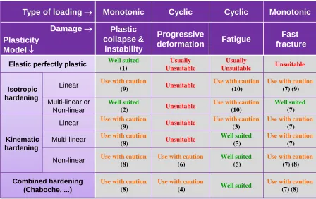
Figure 2 : allowed types of calculation for the different damages in appendix Z C.
(1) Model used essentially for limit analysis.
(2) Identification on lower bound monotonic curves of material.
(3)Results could be not conservative.
(4) Satisfactory results but often very conservatives. (5) Identification on reduced cyclic curves except if the strain range is low: in this case, use mean monotonic curves.
(6) Results can be conservatives when high deformation appears.
(7) Use of "G-theta" method: monotonic loading (no local unload), radial.
(8) Unnecessarily complex model according to the studied damage; caution with the range of identification of parameters.
(9) Suited for specific materials presenting an approximately linear strain hardening. Not adapted to low plastic deformations.
(10) To implement in the case of analysis using stabilized cyclic curve (Z C 3420).
Figure 3 : Models recommendations.
A specific working group was organized in 2014 with experts from APAVE, AREVA NP, AREVA TA, Bureau Veritas, CETIM, DCNS, EDF, ONET Nuclear, SOGETI and Westinghouse. The working group prepared a first version of the appendix to cover all damages except ratcheting for the edition 2017. The
Method
Limit analysis
Double slope method
Elastoplastic analysis Cyclic analysis Damage Excessive deformation (plastic collapse) Plastic instability Fast fracture Progressive deformation (ratchetting) Fatigue
Type of loading Monotonic Cyclic Cyclic Monotonic
Damage Plasticity Model Plastic collapse & instability Progressive deformation Fatigue Fast fracture
Elastic perfectly plastic Well suited
(1) Usually Unsuitable Usually Unsuitable Unsuitable Isotropic hardening
Linear Use with caution
(9) Unsuitable
Use with caution
(10)
Use with caution
(7) (9)
Multi-linear or Non-linear
Well suited
(2) Unsuitable
Use with caution
(10)
Well suited
(7)
Kinematic hardening
Linear Use with caution
(9) Unsuitable
Use with caution
(3)
Use with caution
(7)
Multi-linear Use with caution
(8) Unsuitable
Well suited
(5)
Use with caution
(7)
Non-linear Use with caution
(8)
Use with caution
(6)
Well suited
(5)
Use with caution
(7) (8)
Combined hardening (Chaboche, ...)
Use with caution
(8)
Use with caution
(4) Well suited
Use with caution
appendix will be completed and modified in the 2018 edition to introduce recommendations to deal with ratcheting. Damages covered in the 2017 edition are:
- Excessive deformation (plastic collapse), - Plastic instability,
- Fatigue with two options: direct elastic-plastic analysis to determine the total strain or Ke evaluation,
- Fast fracture.
Elastic and elastic-plastic instability (buckling) are not covered.
This appendix is applicable to class 1 and class 2 components (vessels and piping), class 1 and class 2 supports and reactor internals.
Different types of calculation are covered: limit analysis, elastic-plastic calculations and cyclic analysis. Figure 2 identifies the allowed types of calculation for the different damages.
The appendix provides recommendations of use of the different types of plasticity models for the different damages, as illustrated in Figure 3. Also, recommendations on the suitable material properties to be used are provided, with in particular a link with the data proposed in the RCC-MRx and RSE-M codes. Furthermore, implementations in finite element method and assessments of numerical results are detailed.
3.2 Qualification of active mechanical equipment
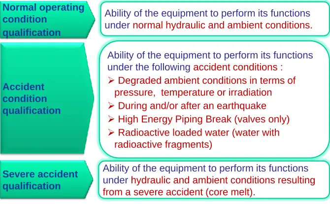
In consistency with AFCEN RCC-E code for electrical components which proposes a Qualification procedure, AFCEN board decided to introduce in the RCC-M code a specific subsection Q on the qualification of mechanical equipment that have accident condition qualification requirements (Figure 4 summarizes the covered conditions).
Figure 4 : Conditions covered by the subsection Q.
A working group was created in 2014 to prepared the proposition, with different members : - Pump suppliers : KSB, SPX CLYDE UNION, FLOWSERVE;
- Valves suppliers : VELAN, VANATOME, EMERSON, KSB; - Test laboratories : SOPEMEA, CETIM;
- AREVA NP; - EDF.
Normal operating condition
qualification
Ability of the equipment to perform its functions under normal hydraulic and ambient conditions.
Accident condition qualification
Ability of the equipment to perform its functions under the followingaccident conditions :
Degraded ambient conditions in terms of pressure, temperature or irradiation
During and/or after an earthquake
High Energy Piping Break (valves only)
Radioactive loaded water (water with radioactive fragments)
Severe accident qualification
The scope of the document implemented in 2017 edition is limited to pumps driven by electric motor and valves (Isolating valves, Control valves, Check valves, Safety relief valves). It is based on :
- French qualification processes currently used for French NPP (plants in operation and EPR in Flamanville 3), based on EDF and AREVA NP experience feedback in the qualification of valves and pumps.
- RCC-E 2012 Subsection B (electrical equipment qualification) which provides general requirements, general rules for the qualification procedure, definitions...
This document is consistent with international standards and codes: ASME QME-1, IEC 60780, IEC 60980.Figure 5 lists the different Qualification strategies proposed in the subsection Q. As this subsection is new, it has been introduced in the 2017 edition as a Rule in Probationary Phase (RPP).
Figure 5 : Qualification strategies proposed in the subsection Q.
4 ON-GOING DEVELOPMENTS FOR FUTURE EDITIONS
4.1 Comparison with European harmonized standards
Since 2013, AFCEN has launched a detailed comparison between RCC-M code and harmonized European standards for the design and the fabrication of vessels (EN 13445 [10]) and piping (EN 13480 [11]). For design rules, this principle of this comparison was based on the performance of relevant cases to identify potential update of the RCC-M code when considered as necessary. In particular, an important activity started in 2015 on the fatigue rules. Details on this activity are given in reference [12]. Concerning the other design rules, the comparison is finished for class 1 components and has not led to major changes in the RCC-M code. The activity is still on going for class2 and class 3 vessels and piping, and for valves of all classes.
This comparison work also led to some minor updates of the fabrication rules of the RCC-M code edition 2016.
Alternative solution, based on the harmonized EN standards, for the design of class 3 vessels and piping of the existing rules of the RCC-M volume D is under preparation. The goal is to specify in the code additional requirements of these standards to reach an equivalent level a quality to address and handle the same safety issues than the existing volume D.
Programme of teststo be carried out on one or more items of “model” equipment
Qualification by test
Qualification by analysis
Qualification by experience
Mixed method
By similarity : use of reference equipment qualified by test to qualify another item of equipment of similar design.
By calculation : intended to demonstrate, using calculation methods or codes, that the loadings endured are admissible in terms of operability.
Operating experience of similar equipment installed in an existing installation with operating conditions similar to those of the proposed equipment.
4.2 Non linear calculations
The AFCEN working Group on non-linear calculation is still active to develop specific recommendations to assess plastic shakedown and ratchetting. The work focuses on :
- The definition of relevant recommendation on the plasticity law choice (in particular Chaboche, Armstrong-Frederick models and Ohno-Wang), on their identification (needed material data, parameter definition) and their application ;
- The definition of suitable ratcheting criterion (for example, local total strain limit).
The goal is to implement this work in the 2018 edition of the RCC-M code.
4.3 Seismic loading in piping design
A new appendix Z N is under preparation for the design of piping under seismic loading condition. This appendix is based on the appendix A1 of the RCC-MRx code, with some consideration for PWR. A dedicated AFCEN working group has been launched in 2016 to evaluate the proposal prepared by AREVA NP.
The first part of the appendix presents the principles to follow for the design of equipment under seismic conditions, in particular concerning the definition of the functional requirement and of the loading combination rules.
The second part of the appendix deals with the definition of the dynamic response of equipment to seismic conditions considered at the design level. It takes into account:
- The seismic floor displacements from the dynamic analyses of civil works;
- The general principles to define equipment model under seismic conditions;
- Different methodologies to determine the seismic response of equipment;
- And the particularities of the seismic calculation of piping systems.
It is aimed to introduce this new appendix in the edition 2018 of the RCC-M code.
4.3.1
Revision of rules for bolted junctions
AFCEN RCC-M design working group has launched an action for the revision of the Annex ZV and F7000 respectively concerning the design and installation of the bolted flange connections.
The draft revision of the appendix Z V proposes two analytical methods to assess the design of bolted connections and a guide for the numerical calculation of a connection:
- The first analytical method is based on the Taylor Forge method. It allows the consideration of tightening variations due to thermal effects.
- The second analytical method is based on the EN 1591-1 standard [13]. As this method is not suitable for metal-to-metal contact, this part of the appendix provides in particular the conditions where the EN 591-1 standard can be applied. For none metal-to-metal contact, this second method is appropriate when :
o the tightness is a major concern, o the considered flange is flexible, o thermal cycles are important,
o the temperature difference between the bolting and the elements to connect is over 50°C, o the thermal expansion coefficient difference between the bolting and the elements to
Also, a revision on the RCC-M code in the F7000 subsection will be proposed to provide a general strategy of gasket testing protocols. A new specific gasket characterization procedure for the determination of the relevant mechanical and sealing parameters required in the calculation following the new proposed RCC-M Annex ZV is detailed. A systematic analysis procedure is introduced to determine the required force to reach the metal-to-metal contact between the compression flanges (for grooved gaskets) or between the compression flange and the gasket limiter ring. This procedure is detailed in [14].
5 CONCLUSIONS
This paper presents the activities of the AFCEN RCC-M subcommittee to update the code with new appendices and subsection to answer to the code users’ needs (as for example non linear calculations or seismic loading in piping design) or to take into account new technical issues of the nuclear industry like the environmental effect in fatigue analyses. These evolutions are prepared by dedicated working groups involving AFCEN expert members but also external experts, and need, for some of them, several years of technical preparation. In particular, the goal is to propose to the code users the best feedback of the nuclear industry practices, but also to consider other industrial practices.
6 REFERENCES
[1]
French Order of 12 December 2005 related to nuclear pressure equipment (ESPN). J.O. N° 19 of
22 January 2006, Paris, France.
[2]
Directive 97/23/EC of the European Parliament and of the Council of 29 May 1997 on the
approximation of the laws of the Member States concerning pressure equipment, Brussels,
Belgium.
[3] Métais, T. et al., 2015, “Overview of French proposal of updated austenitic SS fatigue curves and of a methodology to account for EAF.” PVP2015-45158, ASME 2015 Pressure Vessels and Piping Conference, ASME, USA.
[4] NUREG/CR-6909, Rev. 1, “Effect of LWR Coolant Environments on the Fatigue Life of Reactor Materials,” Draft for comments, 2014
[5] D. R. Tice, D. Green and A. Toft, “Environmentally Assisted Fatigue Gap Analysis and Roadmap for Future Research – Gap Analysis Report”, EPRI 1023012, December 2011
[6] S. Courtin, T. Metais, M. Triay, E. Meister, S. Marie, “Modification of the 2016 edition of the RCC-M code to account for environnementally assisted fatigue”, PVP conférence 2016, Vancouver (CAN), Paper 63127.