Scholarship@Western
Scholarship@Western
Electronic Thesis and Dissertation Repository
8-20-2015 12:00 AM
Experimental Analysis of Parameters Influencing the Bone Burring
Experimental Analysis of Parameters Influencing the Bone Burring
Process
Process
Jonathan KusinsThe University of Western Ontario
Supervisor Dr. Louis Ferreira
The University of Western Ontario Joint Supervisor Dr. Remus Tutunea-Fatan
The University of Western Ontario
Graduate Program in Mechanical and Materials Engineering
A thesis submitted in partial fulfillment of the requirements for the degree in Master of Engineering Science
© Jonathan Kusins 2015
Follow this and additional works at: https://ir.lib.uwo.ca/etd
Part of the Biomechanical Engineering Commons
Recommended Citation Recommended Citation
Kusins, Jonathan, "Experimental Analysis of Parameters Influencing the Bone Burring Process" (2015). Electronic Thesis and Dissertation Repository. 3089.
https://ir.lib.uwo.ca/etd/3089
This Dissertation/Thesis is brought to you for free and open access by Scholarship@Western. It has been accepted for inclusion in Electronic Thesis and Dissertation Repository by an authorized administrator of
(Thesis format: Monograph)
by
Jonathan R. Kusins
Graduate Program in Mechanical and Materials Engineering
A thesis submitted in partial fulfillment of the requirements for the degree of
Master of Engineering Science
The School of Graduate and Postdoctoral Studies The University of Western Ontario
London, Ontario, Canada
ii
The experimental quantification of the bone removal characteristics associated with bone
burring represents a desirable outcome mainly for the selection of optimal parameters. An
experimental apparatus was developed that allowed for concurrent measurement of three
outputs associated with the bone removal process (cutting force, vibration, and
temperature) as a function of various burring-specific parameters. Initial process trends
were established on a uniform sawbone analog through use of a fully balanced
multivariate statistical analysis. A smaller set of optimal and suboptimal parameters were
further validated using a porcine femur. From the parameters tested, an optimal tool
configuration, to avoid high temperature and high vibration, was found to be a 6 mm
sphere burr at a rotational speed of 15,000 rpm, feed rate of 2 mm/s and a path overlap of
50%. This set of parameters also provided flexibility in tool depth/orientation angle
relative to the bone without sacrificing optimal process outcomes.
Keywords
bone burring, bone resurfacing, bone removal parameters, experimental apparatus,
iii
Chapter 1: Jonathan Kusins - sole author
Chapter 2: Jonathan Kusins - study design, data collection, wrote manuscript
Louis Ferreira - study design, reviewed manuscript
Remus Tutunea-Fatan - study design, reviewed manuscript
Chapter 3: Jonathan Kusins - study design, data collection, statistical analysis,
wrote manuscript
Louis Ferreira - study design, reviewed manuscript
Remus Tutunea-Fatan - study design, reviewed manuscript
Chapter 4: Jonathan Kusins - study design, statistical analysis, wrote
manuscript
Louis Ferreira - study design, reviewed manuscript
Remus Tutunea-Fatan - study design, reviewed manuscript
Chapter 5: Jonathan Kusins - study design, data collection, statistical analysis,
wrote manuscript
Louis Ferreira - study design, reviewed manuscript
Remus Tutunea-Fatan - study design, reviewed manuscript
iv
First and foremost, I would like to thank both of my supervisors, Dr. Louis Ferreira, and
Dr. Remus Tutunea-Fatan. The guidance, encouragement, and support that both of you
have provided throughout my graduate studies has been extremely appreciated. Louis,
thank you for providing me with an opportunity to study at the HULC; something that I
will come to miss. Remus, your willingness to always discuss various issues at hand was
appreciated and your drive for weekly meetings definitely kept me on the ball throughout
this project. Thank you both for your mentorship throughout.
I would also like to extend my thanks to the entire HULC team. Thank you for providing
me with an enjoyable working environment, inside and outside of the lab. I am honored
to be part of the TankFM team and grateful for all the listeners/students that made it
possible.
Finally, I would like to express my thanks to my family. Thank you Mal and Caleb for
helping me along in this process and if not for either of you, I may of never considered
graduate studies in the first place. Mom and Dad, thank you for your unwavering support
throughout and for providing me with a getaway cottage that was desperately needed at
v
Abstract ... ii
Co-Authorship Statement... iii
Acknowledgments... iv
List of Tables ... x
List of Figures ... xii
List of Equations ... xv
List of Appendices ... xvi
Chapter 1 - Introduction ... 1
1.1 Structure and Mechanical Properties of Bone ... 1
1.1.1 Bone Necrosis ... 3
1.2 Bone Resurfacing ... 3
1.2.1 Manual Resurfacing Procedures ... 5
1.2.2 Robotic Methods ... 8
1.2.3 Bone Removal Tools... 11
1.3 High Speed Bone Burring Characteristics ... 13
1.3.1 Process Parameters... 13
1.3.2 Outcome Measurements... 18
1.4 State-of-the-Art in Quantifying the Bone Burring Process... 21
1.5 Rationale ... 24
1.6 Objectives and Hypotheses ... 26
1.7 Thesis Overview ... 28
Chapter 2 - Development of Experimental Apparatus for Investigation of Bone Burring ... 30
vi
2.2.1 Burring Tool Holder ... 33
2.2.2 Workpiece Positioning ... 35
2.3 Measurement of Dependent Variables ... 37
2.3.1 Data Acquisition System... 37
2.3.2 Cutting Force Measurement ... 38
2.3.3 Vibration Measurement ... 40
2.3.4 Temperature Measurement ... 42
2.4 Sample Experiment ... 44
2.4.1 Signal Post Processing ... 48
2.4.2 Sample Experiment Results ... 56
2.5 Chapter Summary ... 56
Chapter 3 - Experimental Analysis of the Effect of Process Parameters on Selected Outcome Measurements ... 58
3.1 Selection of Process Parameters ... 58
3.1.1 Feed Rate Normalization ... 63
3.2 Statistical Analysis ... 66
3.3 Effects of Process Parameters on Outcome Measurements ... 67
3.3.1 Cutting Force ... 67
3.3.2 Vibration ... 68
3.3.3 Temperature ... 68
3.4 Chapter Summary ... 78
Chapter 4 - Process Parameter Selection for Clinical Implementation ... 80
4.1 Reduction of Parameters ... 80
4.1.1 Criteria for Reduction of Parameters ... 81
vii
4.3 Local Minimums for Temperature and Vibration ... 86
4.3.1 Heuristic Filtering Results ... 86
4.3.2 Vibration ... 86
4.3.3 Temperature ... 86
4.4 Local Maximums of Temperature and Vibration ... 89
4.4.1 Heuristic Filtering Result ... 89
4.4.2 Vibration ... 89
4.4.3 Temperature ... 89
4.5 Absolute Maximums of Temperature ... 92
4.5.1 Heuristic Filtering Results ... 92
4.5.2 Vibration ... 92
4.5.3 Temperature ... 92
4.6 Absolute Maximums of Vibration ... 94
4.6.1 Heuristic Filtering Results ... 94
4.6.2 Vibration ... 94
4.6.3 Temperature ... 94
4.7 Chapter Summary ... 97
Chapter 5 - Experimental Validation of Process Parameters on Porcine Cadaver Model ... 100
5.1 Parameter Selection ... 100
5.2 Specimen and Data Preparation ... 103
5.2.1 Specimen Selection ... 103
5.2.2 Specimen Preparation ... 104
5.2.3 Bone Removal Burring Testing and Data Preparation ... 104
viii
5.4 Effects of Process Parameters on Outcome Measurements - Optimal Set ... 110
5.4.1 Cutting Force ... 110
5.4.2 Vibration ... 111
5.4.3 Temperature ... 111
5.5 Effects of Process Parameters on Outcome Measurements - Suboptimal Set .... 111
5.5.1 Cutting Force ... 116
5.5.2 Vibration ... 116
5.5.3 Temperature ... 116
5.6 Chapter Summary ... 119
Chapter 6 - General Discussion and Conclusions ... 122
6.1 Summary and General Discussion ... 122
6.2 Strengths and Limitations ... 126
6.3 Future Work ... 127
6.4 Conclusion ... 128
References ... 129
Appendix A: Developed Experimental Apparatus Component Drawings ... 135
Appendix B: Supplementary Specification Sheets ... 146
Appendix C: Supplementary Testing Files ... 149
Appendix D: Statistical Analysis Guide ... 160
Appendix E: Burring Trials and Associated Force Results from Results Presented in Chapter 4 ... 163
Appendix F: Burring Trials and Associated Force Results from Results Presented in Chapter 5 ... 169
x
Table 3.1: Selected levels of process parameters... 62
Table 3.2: Summary of MANOVA results ... 69
Table 3.3: Summary of ANOVA results - Fx ... 69
Table 3.4: Summary of ANOVA results - Fy ... 69
Table 3.5: Summary of ANOVA results - Fz ... 70
Table 3.6: Summary of ANOVA results - vibration ... 70
Table 3.7: Summary of ANOVA results - temperature ... 70
Table 4.1: Summary of statistical analysis for process parameters that resulted in local minimums of temperature and vibration ... 87
Table 4.2: Summary of statistical analysis for process parameters that resulted in local maximums of temperature and vibration ... 90
Table 4.3: Summary of statistical analysis for process parameters that resulted in absolute maximums of temperature ... 93
Table 4.4: Summary of statistical analysis for process parameters that resulted in absolute maximums of vibration ... 95
Table 5.1: Optimal combination of process parameters ... 102
Table 5.2: Suboptimal combination of process parameters ... 103
Table 5.3: Descriptive statistics of outcome measurements - optimal set ... 112
xi
Table 5.6: Summary of statistical analysis for process parameters that resulted in local
maximums of temperature and vibration ... 118
Table E.1: Reduced sample set #1: local minimums of temperature and vibration ... 163
Table E.2: Reduced sample set #2: local maximums of temperature and vibration ... 164
Table E.3: Reduced sample set #3: absolute maximum for temperature ... 165
Table E.4: Reduced sample set #4: absolute maximum for vibration ... 167
Table F.1: Optimal combination set of process parameters ... 169
xii
Figure 1.1: Structural makeup of bone ... 4
Figure 1.2: Bone removal process ... 6
Figure 1.3: Mastoid process location on the skull ... 7
Figure 1.4: Automated robotic surgery ... 10
Figure 1.5: Orthopaedic reamer ... 11
Figure 1.6: High speed rotary burring tool ... 12
Figure 1.7: Midas Rex Legend rotary burring tool ... 15
Figure 1.8: Design parameters used for bone burring (depth of cut + overlap)... 16
Figure 1.9: Design parameters used for bone burring (inclination angle + tilt angle) ... 17
Figure 2.1: Tool holder with adjustable orientation ... 34
Figure 2.2: Workpiece positioning system with adjustable horizontal position ... 36
Figure 2.3: Data acquisition system ... 37
Figure 2.4: ATI 3-axis load cell placement ... 39
Figure 2.5: Uni-axial Endevco accelerometer placement ... 41
Figure 2.6: Infrared pyrometer placement ... 43
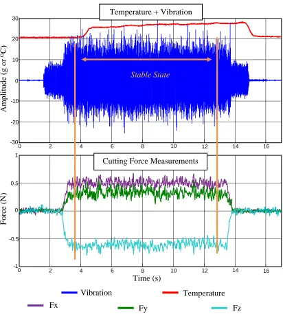
Figure 2.7: Simultaneous measurements of dependent variables ... 46
Figure 2.8: Fast Fourier transform of steady state vibration data ... 47
xiii
Figure 2.11: Steady state measurement of cutting force (Z-direction) ... 53
Figure 2.12: Steady state measurement of vibration ... 54
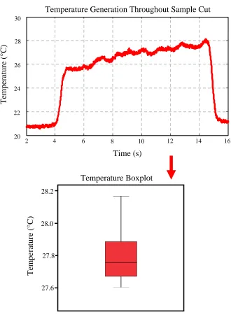
Figure 2.13: Temperature measurement obtained from sample cut ... 55
Figure 3.1: Quantifying cooling of the workpiece during a burring trail ... 64
Figure 3.2: Temperature normalized to the center of the burring tool ... 65
Figure 3.3: Main effects of process parameters on cutting force (Fx, Fy, and Fz) ... 71
Figure 3.4: Main effects of process parameters on temperature and vibration ... 72
Figure 3.5: Maximum and minimum measurements for cutting force - Fx... 73
Figure 3.6: Maximum and minimum measurements for cutting force - Fy... 74
Figure 3.7: Maximum and minimum measurements for cutting force - Fz ... 75
Figure 3.8: Maximum and minimum measurements for vibration ... 76
Figure 3.9: Maximum and minimum measurements for temperature ... 77
Figure 4.1: Measurements from experimental matrix... 84
Figure 4.2: Heuristic filtering process ... 85
Figure 4.3: Temperature measurements of the sphere and cylinder tools at varying inclination and tilt angles ... 88
Figure 4.4: Local minimums and maximums of temperature and vibration measurements ... 91
Figure 4.5: Absolute maximums of temperature and vibration ... 96
xiv
Figure 5.3: Feed rate normalization for porcine bone ... 109
Figure 5.4: Temperature and vibration measurements of sawbone vs. porcine - optimal parameter set ... 113
Figure 5.5: Sensitivity of tool type to changes in inclination angles ... 115
Figure 5.6: Temperature and vibration measurements of sawbone vs. porcine -suboptimal parameter set ... 117
Figure C.1: Noise characterization of accelerometer ... 150
Figure C.2: Noise characterization of pyrometer ... 150
Figure C.3: Noise measurements of 3 DOF load cell ... 151
Figure C.4: Force measurements of original designed workpiece clamp ... 153
Figure C.5: Force measurements with adjustable clamp ... 154
Figure C.6: Sample outputs from load cell verification tests (0, 2N) ... 155
Figure C.7: Sample outputs from load cell verification tests (4N, 6 N) ... 156
Figure C.8: Alignment of pyrometer ... 159
Figure G.1: Developed process to synthesize sounds associated with bone burring ... 172
Figure G.2: Authentic and synthesized sound at 45,000 rpm ... 177
Figure G.3: Authentic and synthesized sound at 15,000 rpm ... 178
xv
Equation 2.1: SNR calculation ... 48
Equation G.1: Principle frequency synthesis ... 174
Equation G.2: Second harmonic frequency synthesis... 174
Equation G.3: Third harmonic frequency synthesis ... 174
Equation G.4: Frequency to time domain translation ... 174
xvi
Appendix A: Developed Experimental Apparatus Component Drawings ... 135
Appendix B: Supplementary Specification Sheets ... 146
Appendix C: Supplementary Testing Files ... 149
Appendix D: Statistical Analysis Guide ... 160
Appendix E: Burring Trials and Associated Force Results from Results Presented in Chapter 4 ... 163
Appendix F: Burring Trials and Associated Force Results from Results Presented in Chapter 5 ... 169
Chapter 1
-
Introduction
1
OVERVIEW: Bone removal is required in multiple surgical resurfacing
procedures. A common method to resurface bone involves using a high
speed rotary tool for bone removal purposes. This chapter will describe the
structure and mechanical properties of bone, and the clinical procedures
that require the removal of bone. In addition, both manual and automated
processes which have been adapted currently in the clinic are discussed.
Current state-of-the-art studies involving optimizing process parameters
associated with the burring procedure are summarized. Associated
statistical methods related to the current project are explained. The chapter
ends with rationale, objectives and hypothesis associated with the current
body of work.
1.1
Structure and Mechanical Properties of Bone
Bone is a stiff skeletal material that provides the supportive framework to the body. The
major functions of bone include: support of soft tissues, provision of levers for muscles,
and protection of internal organs. Bone is a heterogeneous mix of materials and cells that
can be further divided into organic and inorganic components. The organic portion of
bone consists of the cells that build (primarily osteoblasts) or degrade (primarily
osteoclasts) bone, collagen, bone matrix proteins, and blood vessels that supply nutrients.
The inorganic component of bone, which is produced by bone cells, consists primarily of
characterize the mechanical properties of bone and is quantified using a measurement of
bone mineral density (BMD) [1, 2]. Unique interactions between the organic and
inorganic components of bone, lead in regular bone turnover; an important feature of
bone that allows for natural self–repair to injury, or remodeling in response to mechanical
stimuli [3, 4]. Therefore, it is important to conceptualize bone as a living substance
within the body, one that reacts to external stimuli and contains its own network of blood
vessels and cells.
Bone is divided into two fairly distinct structural organizations: cortical (compact) bone
and cancellous (spongy) bone. The difference between the structural types is
distinguishable to the naked eye due to several distinct differences between structures [5].
Cortical bone is a solid rigid material. A cortical layer makes up the outer shell of the
bone and is much denser and stiffer than cancellous bone [1]. Cancellous bone is porous
throughout and is less uniform than cortical bone [6, 7]. The mechanical properties of the
bone are highly variable and are mainly due to the variation in the apparent density which
differ by anatomical location as well as various factors such as age, overuse and
pharmaceutical interventions [8-11].
The gross morphology of human bones can be distinguished into four classifications:
long bones (femur, tibia, ulna and radius), short bones (wrist and ankle bones), tabular or
flat bones (skull and scapula), and irregular shaped bones (located within the skull and
parts of the pelvis). Long bones are usually thick walled, hollow tubes (filled with bone
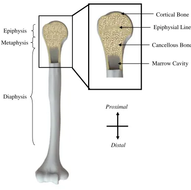
marrow), and have expanded ends. The regions of the long bone are classified as the
metaphysis (between epiphysis and diaphysis) (Figure 1.1). The epiphysis is the
elongated ends of the long bone and have a thin cortical shell that encloses the cancellous
bone. The diaphysis of the bone is primarily composed of a thick cortical shell (cortex)
that surrounds the medullar canal filled with bone marrow.
1.1.1
Bone Necrosis
As bone is a living organism, exposure to high temperature, even for a short period of
time, could result in permanent thermal damage (osteonecrosis). Previous studies have
attempted to quantify the severity of osteonecrosis dependent on the temperature that the
bone is exposed to and the duration of time that may cause damage to the bone [12-15].
Previous studies give indication that there is a distribution of temperature levels for
specified time durations that can possibly lead to osteonecrosis. Lundskog et al. found
histochemical evidence of thermal damage when the bone was heated to 50 ᴼC for 30
seconds [12]. Eriksson et al. indicated that bone tissue is sensitive to temperatures in the
range of 47-53 ᴼC for the duration of 1 minute [13, 14]. Specific to an orthopaedic cutting
process, Krause et al. used a threshold of 50 ᴼC to determine osteonecrosis [15].
Collectively, these studies indicate the importance of avoiding exposing bone tissue to
elevated temperatures as it may result in hindered bone remodeling post operation.
1.2
Bone Resurfacing
Bone removal or resurfacing is required in various surgical treatments. The surgical
procedures and tools involved vary by surgical intervention. In context with the overall
theme of this work, procedures that involve or have the potential to involve high speed
Cortical Bone
Cancellous Bone
Marrow Cavity Epiphysial Line
Proximal
Distal Epiphysis
Metaphysis
Diaphysis
The structural components of a long bone, humerus shown above, are illustrated in
the diagram above. The long bone is divided into three sections including the:
epiphysis, metaphysis, and diaphysis. The bone itself is composed of two main distinct
structural organizations: cortical and cancellous bone.
1.2.1
Manual Resurfacing Procedures
1.2.1.1
Orthopaedics
Joint replacement/resurfacing is a surgical procedure used with the goal of alleviating
pain and restoring function to a damaged joint (hip, knee, shoulder). Although there
exists many clinical conditions that may require joint replacements for treatment, the
majority of these conditions can be grouped into the broad categories of arthritic
conditions and fractures [16-18]. In the majority of arthritic conditions, the joint surface
becomes damaged as a result of chronic inflammation (as in the case of rheumatoid
arthritis) or chronic wear and tear (as in the case of osteoarthritis). If left untreated,
progressive joint immobilization and loss of function will ensue. Currently, several types
of joint replacements are used clinically which include: total joint (whole joint is
replaced), hemiarthroplasty (one side of the joint is replaced) and joint resurfacing (only
the articular surface is replaced).
The surgical procedure for a joint replacement calls for a synthetic material to replace the
damaged articular cartilage and/or joint. To insert the joint replacement into a patient, a
volume of the bone must first be removed to provide a cavity for insertion. The
machining and removal of the bone can be performed by multiple means and may
individually or collectively involve: drilling, reaming, or milling to prepare the cavity.
These surgical procedures are traditionally performed manually by a surgeon. After the
cavity is prepared, the joint replacement is inserted and fixed in placed. Fixation of the
joint replacement can be performed by several methods which include: screw, cement, or
press-fit. Regardless of the fixation technique, a cavity must be formed for the bone to
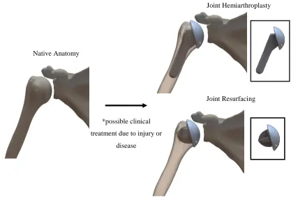
Joint resurfacing arthroplasty offers an appropriate application for use of a high speed
rotary tool as it may require the bone cavity to be precisely shaped. The procedure is
considered to be a bone-conserving alternative to total joint replacement as the joint
resurfacing replacements are closely shaped to the patients anatomy with shorter stems
used for fixation [19, 20] (Figure 1.2). The resurfacing procedure may require a complex
bone cavity with high geometrical accuracy to attain secure fixation and may only be
achievable using a small diameter (approximately 4 mm) rotary burring tool.
Native Anatomy
Joint Resurfacing
*possible clinical treatment due to injury or
disease
Figure 1.2: Bone removal process
Various types of implants are used in orthopaedics as shown above. To fixate the
implant into a patient; bone must first be removed to form a cavity to allow for
insertion. A possible implementation for a high speed rotary tool would be the process
of bone removal to form a cavity which may require intricate geometries that can be
achievable using only a small diameter burring bit.
1.2.1.2
Neurotology
Neurotology is a branch of medicine that deals with treating disorders of the ear. Otologic
surgeries are performed on the temporal bone which is located on the sides of the skull
and house the structures vital to hearing (Figure 1.3). The temporal bone is divisible into
four parts: the squamous, mastoid, petrous, and tympanic portions. Relevant to the
present project is a specific surgery known as a mastoidectomy.
A mastoidectomy is surgical procedure that requires the removal of temporal bone within
the mastoid region, using a high speed rotary tool. A mastoidectomy is performed to
expose the cells within the mastoid structure, which may be required due to
cholesteatoma (cyst), or mastoiditis (infection) [21]. The procedure is especially relevant
as the surgical practice currently involves the use of a high speed rotary tool for bone
removal within the temporal bone region.
Temporal Bone
Mastoid Process
Figure 1.3: Mastoid process location on the skull
A mastoidectomy is a surgical procedure that involves removing the outer surface of
temporal bone on the skull. A high speed rotary tool is currently used clinically to
1.2.2
Robotic Methods
Automated robotic bone burring first appeared with commercial success in surgical
procedures which involved joint replacement and resurfacing. Automated robotic burring
takes advantage of the rigidity of the bone and high accuracy of the registration
techniques developed. The registration techniques allow for pre-operative planning of the
automated tool path trajectory comparable to that of computer numerical control (CNC)
machining. There are many advantages of employing robotic systems including:
increased accuracy and precision that lead to improvements in surgical outcomes
compared to the manual procedure [22-24]. Within the orthopaedic field, three developed
systems are the Robodoc, MAKO™ platform, and Acrobot.
The Robodoc (Integrated Surgical Supplied Ltd., Sacramento, CA) surgical system was
the first orthopaedic surgical robot approved by the Food and Drug Association (FDA)
[25]. Clinical use of the automated burring robot, Robodoc, was implemented in 1992 for
femoral canal preparation in total hip arthroplasty [26]. Results showed, through patient
and cadaveric studies, that the Robodoc was able to match results compared to the
manual technique as well as provide better stability and fit in placement of the femoral
component in total hip arthroplasty [23, 24, 27]. Additionally, the Robodoc removed less
bone within the same procedure compared to the manual techniques [28].
The MAKO® surgical robot (MAKO Surgical Corp., Fort Lauderdale, FL) is a passive
robot which assists the surgeon in partial knee and total hip replacement by providing
haptic feedback (Figure 1.4). The MAKO® surgical robot limits machining errors during
removing bone [29]. The MAKO® platform has been found to significantly increase the
accuracy and precision involved in total hip arthroplasty in cadaveric studies [30].
The Acrobot is an active constraint control robot that has had clinical success in knee and
hip replacement surgery. The Acrobot features a control system; which implements tool
tracking to aid the surgeon in live surgery [31]. The Acrobot has also shown to be
effective in in-vitro and in-vivo studies to aid the surgeon in providing feedback of the
tool for total knee replacement surgeries [32].
Additionally, several robotic systems have been developed in an in-vitro setting to prove
the feasibility of implementing robotic system for mastoidectomy [33, 34]. Danilchenko
et al. successively burred a cavity in the mastoid on three separate specimens using a
industrial robot equipped with a high speed rotary tool as an end effector [33]. Federspil
et al. also had success with experimental burring of two human skulls using an industrial
robot and a high speed rotary tool [34].
The emergence of robotic systems provides an opportunity to implement feedback loops
which monitor burring data and adjust control parameters accordingly. A full
understanding of the characteristics associated with bone burring would prove beneficial
The MAKOplasty® surgical robot is a passive robotic system that assists the surgeon by providing haptic feedback to the surgeon during partial knee resurfacing.
Additional information, such as location of the tool, is provided by the MAKO® system
that would otherwise would not be available in a traditional manual surgical
operation.
Figure 1.4: Automated robotic surgery1
1
Modified from MAKOplasty® Surgical Robot [Internet].MAKO® Surgical Corp., Fort Lauderdale, FL; cited [June 26, 2015]. Available from: http://www.makoplasty.com/.
1.2.3
Bone Removal Tools
1.2.3.1
Reaming (Low Speed)
Low speed rotational cutting tools, also known as reamers, are used in a variety of
orthopaedic surgeries which involve nail insertion into long bones (primarily the tibia)
and resurfacing of the bone for joint replacement. An orthopaedic reamer, used for joint
replacement, has an end bit of approximately 30 mm in diameter and is used to produce
axisymmetric cavities for joint replacement. The reamer design depends primarily on the
manufacturing company. Typical reamer design for joint replacement is often comprised
of reamer blades, varying blade orientations, and altering the gap between the blades. The
rotary speed of the reamer is typically between 250 to 500 revolutions per minute (rpm).
Current research studies exploring bone removal using the reamer show high
temperatures involved during the surgical procedure that could potentially lead to
necrosis [35, 36]. Additionally, previous in-vitro studies have found that the design of the
reamer (number of blades, spindle speed) can result in varying the temperatures involved
[37, 38].
An orthopaedic reamer/drill with reamer attachment is pictured above. The reamer bit
shown is 30 mm in diameter and spins at rotary speed of 250 rpm.
1.2.3.2
Burring (High Speed)
High speed rotary tools, used primarily for burring of the bone, are used in various
surgical settings; including orthopaedic and neurotologic applications. The burring tool is
designed to be a hand held tool which spins at high rotational speeds during the bone
removal process (10,000 to 80,000 rpm). The burring end bit is typically in the range of 2
to 10 mm which allows for more intricate operations to be performed by the burring tool
compared to the larger reaming tool. The common high speed burring tool is composed
of a motor (handpiece), burring bit, as well as an 'attachment' to cover the shaft of the
burr. The design of the tool and bits available depend on the manufacturer. Popular
manufactures include Medtronic (Medtronic Inc, Minneapolis, MN) and Anspach (The
Anspach Effort, Inc., Palm Beach Gardens, FL). The Medtronic's Midas Rex Legend
Stylus system rotates at spindle speeds between 200 to 75,000 rpm and is controlled via
an integrated closed loop controller. The Anspach Emax 2 Plus is an alternative burring
tool which spins at speeds between 10,000 to 80,000 rpm. Previous in-vitro studies have
attempted to quantify the temperatures and cutting forces involved within the burring
process [39-42].
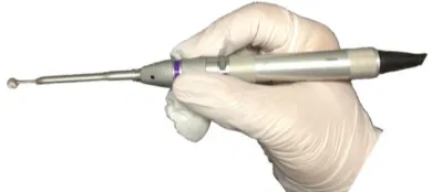
Figure 1.6: High speed rotary burring tool
The Midas Rex Legend rotary burring tool is pictured above. The burring bit is
typically small in diameter (2 to 10 mm) and can spin at speeds of up to 75,000
1.3
High Speed Bone Burring Characteristics
To maximize the efficiency of the bone burring process, care must be taken into the
choice of process parameters (rotary speed, type of cutter, depth of cut) to reduce the
dynamic effects and temperature rises associated with high speed burring. The selection
of process parameters has been shown to have an effect on the outcome measurements,
such as temperature generation and cutting force [39-42].
1.3.1
Process Parameters
The main process parameters used in previous studies that involve a high speed rotary
tool for bone burring include [34, 39-41, 43-46]:
Shape of burring bit
Diameter of burring bit (mm)
Rotational speed of the tool (rpm)
Depth of cut (mm)
Feed rate (mm/s)
Cutting track overlap (%)
Inclination angle (°)
Tilt angle (°)
The shape of the burring bit varies on the manufacturer. There are two main types of
burring bits; fluted and diamond coated. Fluted bits are used to remove larger volume of
bone as they have cutting flutes running up the bit. Different shapes of fluted burring bits
exist and include: sphere, cylinder, acorn, match and oval (Figure 1.7). Diamond coated
to abrade the bone. The diameter of the bits range from 1 to 10 mm. The rotational speed
of the tool is the speed of the burr measured in revolutions per minute (rpm). Typical
speeds of a high speed rotary tool are in the ranges of 10,000 to 80,000 rpm.
The depth of cut (mm) is defined as the thickness of material that is removed with one
pass of the burring tool (Figure 1.8). The feed rate (mm/s) of the tool is the linear
advancement rate of the tool itself. The burring process of bone, commonly employs very
shallow depths of cut (<1 mm) with feed rates in the range of 1 to 10 mm/s [44].
Additionally, cutting track overlap (%) is defined as the overlap of burring paths between
successive paths of the burring tool (Figure 1.8).
Inclination and tilt angles (°) make up the orientation of the tool with respect to the
workpiece. The inclination and tilt angle are defined in Figure 1.9. The angle of the tool
is of particular importance in the context of surgical procedures due to the limited milling
cavities that may be unavoidable. The direction of the cut with respect to the previous
burring path (conventional and climb milling) is also of importance when designing a
tool path trajectory. Down milling is typically desired as the tool leaves the workpiece
with zero force compared to up milling which leaves the workpiece with force on the bit.
The process parameters mentioned above collectively represent those that can be varied
in the design of a tool path trajectory. The most effective combinations of parameters,
that minimize temperature, forces and vibrations, as well as providing a realistic
Figure 1.7: Midas Rex Legend rotary burring tool
Motor (Handpiece) Burring Attachment
Burring Bit
Cylindrical Burring Bit Spherical Burring Bit
A CAD rendering of the Midas Rex Legend rotary burring tool is shown above. The
burring tool consists of three main components: motor, attachment, and a burring
bit. The bits are long and slender (2.35 mm shank diameter) and come in various
sizes dependent on the manufacturer. Two common bits are the cylindrical and
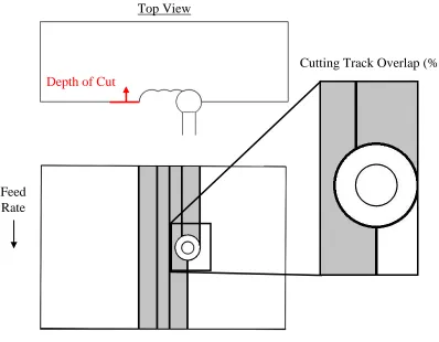
Depth of Cut
Top View
Cutting Track Overlap (%)
Figure 1.8: Design parameters used for bone burring (depth of cut + overlap)
Characteristic parameters (overlap and depth of cut) associated with the bone burring
process are illustrated above. Depth of cut (mm) is defined as the thickness of the
material that is removed during a burring run. Overlap is the % of overlap between
successive cutting tracks (shown in the inset is 50% overlap). Feed
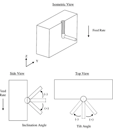
Isometric View
Feed Rate
Z
Y
Side View Top View
(-)
(+)
(+) (-)
Inclination Angle Tilt Angle
Figure 1.9: Design parameters used for bone burring (inclination angle + tilt angle)
Characteristic parameters (inclination and tilt angle) associated with the bone
burring process are illustrated above. Shown in the isometric view is the tool oriented
at a normal to the workpiece face. Inclination angle is the rotation of the tool about
the Y axis. Tilt angle refers to rotation of the tool about the Z axis. Feed
1.3.2
Outcome Measurements
Various outcome measurements are used to evaluate the process parameters in terms of
safety and accuracy of the burring process. To quantify the process outcomes, various
transducers are instrumented to monitor the burring process. Relevant methods to
instrument and quantify the associated outcome measurements are discussed in the
following subsections.
1.3.2.1
Cutting Force
Cutting force is the total force exerted in three planes by the burring tool in order to
remove material from the workpiece. Cutting force is important in the context of the
burring process as it can be used in the design of robotic systems to optimize accuracy
and safety of the procedure [41, 46]. Experimental methods, involving bone burring, have
been performed using strain measurements to quantify the cutting force between the
workpiece and tool [41, 43, 46].
Dillon et al. selected a force sensing device (ATI Six-Axis Sensor System) which was
mounted between the robotic arm and burring tool [41]. Federspil et al. selected a force
and torque sensor (JR-3 Inc., Woodland, CA) which had a range of 63 N and was placed
between the robot arm and burr [43]. Sugita et al. also selected a 6 DOF force sensor
installed in the spindle with rated values of 400N, 800N, and 40 Nm [46]. An additional
method to measure the cutting force during a burring procedure was performed by
Plaskos et al. which used a piezoelectric dynamometer. The dynamometer was placed
To quantify cutting force and allow for comparison between process parameters, Dillon
et al. and Plaskos et al. averaged the cutting forces from the entry to exit points of the
burring trial [41, 45]. Federspil et al. and Sugita et al. did not compute an average cutting
force, as the authors reported only a single run to validate their developed automated
systems [43, 46].
1.3.2.2
Vibration
The vibration generated due to the burring procedure has a direct influence on the
accuracy and surface finish of the cut. Additionally, vibration generated may introduce
noise into the system that may be undesirable for other transducers monitoring the
burring process.
To knowledge, no previous experimental study has directly measured the vibration of the
tool during a bone burring process. Indirect attempts have been made by Denis et al. by
measuring the surface flatness, which is a product of the dynamic effects of the tool [39].
Federspil et al. also measured the vibrations of a skull during robotic burring using a
piezoelectric crystal that was mounted to the workpiece [34]. Vibrations of a dental
handpiece have been previously studied, primarily in the context of hand-arm vibration
exposure to dentists using high speed rotary dental tools [47, 48]. Rytkonen et al.
mounted a piezoelectric charge accelerometer (B&K 4393) to the handpiece using a
fabricated adapter and subsequently glued the adapter to the handpiece [48]. Additional
research has also been devoted to quantifying harmful effects resulting from hand-arm
piezoelectric accelerometers to the tool to report the total vibration over a certain
bandwidth of frequencies for a duration of time [49-51].
To quantify the vibration of a single burring trial, Federspil et al. reported the
measurements quantified by an accelerometer mounted on the workpiece over the entire
trial (magnitudes less than 1.5 g) [34]. As only one trial was performed within the
mentioned experimental trial, no protocol to allow for comparison of the accelerometer
measurements was taken. In other applications for quantifying the dynamic effects of
hand held tools, and allow for comparisons to be quantified, a weighted vibration is
generally calculated dependent on a bandwidth of frequencies that is important to the
author [48-51].
1.3.2.3
Temperature
In a conventional machining process, a bulk of the energy consumed is converted into
heat [52]. If high temperatures were to occur during a bone resurfacing procedure,
specifically bone burring, thermal damage (osteonecrosis) could occur. If osteonecrosis
occurs, the bone would lose its ability to remodel and repair itself post surgery. This loss
of remodeling has been linked to loosening in joint replacements which in turn may
require a subsequent revision surgery [53]. Therefore, it is vital to quantify process
parameters that may lead to osteonecrosis in order to avoid them.
Experimental methods have been developed to measure temperature generation during
the bone removal process. Temperature systems can be broken into two distinct methods:
contact and non-contact. The contact method commonly involves a thermocouple or
contact method of quantifying temperature of the workpiece has been implemented
primarily in quantifying the temperature of the bone during a drilling process [54-56].
More relevant to bone burring, common measurement systems used to quantify
temperature has been a non-contact method of an infrared pyrometer [39, 40]. Shin et al.
selected an IKS-T14-06 model from Infrapoint® with accuracy of 1 ᴼC and trailed the
burring process by 10 and 20 mm; whereas, Denis et al. selected a Raytek ThermalertTX
pyrometer with accuracy of 1.5 ᴼC. Infrared cameras have also been adapted to measure
temperature in in-vivo joint resurfacing procedures [35, 36].
To quantify temperature and allow for comparison between multiple burring trials, the
average temperature of a burring trail was calculated from the start to exit points of the
process [39, 40].
1.4
State-of-the-Art in Quantifying the Bone Burring Process
Previous studies have aimed to characterize the process parameters involved in the bone
burring process [34, 39-41, 43-46]. These studies have investigated the effects of varying
the process parameters on temperature generation and cutting force applied in both
manual and robotic bone removal procedures. The clinical relevance of the studies vary
dependent on the field but are primarily performed in the orthopaedic and neurotological
fields with a main goal of finding an optimal combination of parameters to minimize or
maximize the outcome measurement [34, 39-41, 43-46].
Shin et al. and Denis et al. examined the effects of varying the process parameters and
used temperature as an outcome measurement [39, 40]. Both studies used an infrared
Denis et al. investigated the influence of feed per tooth and milling speed using a high
speed milling machine [39]. It was found that increasing the feed per tooth and
decreasing the milling speed altered the temperature experienced by the bone. The
burring parameters were varied between various feed rates and rotational speeds of the
tool between 10,000 to 40,000 rpm. Denis et al. recommended that in order to limit rises
in temperature, the feed rate per tooth should be increased and the milling speed should
be decreased [39].
A similar study was performed by Shin et al. which investigated temperature rise using a
spherical burr [40]. Feed rates were adjusted at levels of 2, 3.2, 5.5, and 9.8 mm/s. The
depth of cut was adjusted from 0.3, 0.5, and 1 mm and the burring was performed in a
range of 30,000 to 50,000 rpm. Shin et al. concluded that increasing feed rate and
decreasing the depth of cut was desirable to reduce thermal damage during bone burring
[40].
Previous studies have also varied the process parameters and examined the effects they
have on the applied cutting force. Plaskos et al. aimed to quantify the cutting forces
involved in a high speed burring process with very shallow depths of cut [45]. The
authors demonstrated that the cutting forces are significantly different in high speed
machining processes compared to a traditional means of machining using lower speeds
[45].
Dillon et al. investigated the effects of choosing certain combinations of parameters for
use in a robotic mastoidectomy [41]. The authors' combination of parameters included
cutting velocities, and bone types (temporal bone and the mastoid). The burring process
was conducted using an autonomous robot and used human temporal bone specimens.
The authors concluded that certain combination of parameters were more efficient than
others and high linear cutting velocities should be combined with shallow depths of cut
for optimal performance. The authors also suggested the possibility of using different
parameters within different regions of bone [41].
Arbabtafti et al. performed experimental measurements in order to validate a haptic
feedback system they developed. The effects of feed rate, spindle speed, and drill angle
were examined with respect to their effects on resulting burring forces. Feed rates in the
range of 1.4 to 3 mm/s, spindle speeds between 15,000 to 31,000 rpm and drill angles of
22 to 63ᴼ were chosen as the process parameters. Arbabtafti et al. reported that increasing
feed rate and decreasing rotational speed resulted in an increase of burring force.
In addition to the studies that varied certain process parameters to view the effects, other
authors have attempted to quantify the burring process dependent on their application,
primarily for feedback controllers for automated burring. Sugita et al. developed a
force-feedback control loop to monitor forces during burring and to select an optimal feed rate
to reduce temperature generation and surgical procedure time [46]. Federspil et al.
demonstrated the feasibility of automating the burring process on temporal bone. The
authors through separate studies, detail a burring path strategy and evaluated it using
various feedback controllers [34, 43]. The study reports the first development of an
1.5
Rationale
Experimental quantification of the bone removal characteristics associated with bone
burring represents a desirable outcome for an array of surgical applications, manual or
automated, and also in the design of the burring tools themselves. Optimizing the burring
process, via the selection of process parameters offers the potential to improve the
success rate of clinical procedures by limiting osteonecrosis, which may occur with
selection of suboptimal parameters [39, 40, 46]. Subsequently, as robotic technology
continues to emerge, the ability to control process parameters becomes less challenging.
Previous authors have identified the importance of experimentally quantifying the bone
removal characteristics associated with bone removal [34, 39-41, 43-46]. However, as the
burring process itself offers a large array of process parameters (depth of cut, cutting
overlap, rotational speed, feed rate, angle of tool, type and diameter of tool) and a vast
amount of levels within each process parameter, a full factorial analysis involving a bulk
of the process parameters has not been undertaken. Previous authors were required to fix
certain process parameters to levels within the machining process, which in turn limits
the amount of combinations that were tested. For example, Shin et al. fixed the burring
process parameters by selecting a 9.1 mm sphere burr oriented at a normal to the
workpiece face and a fully immersed burring path [40]. The experimental analysis
conducted by Shin et al. included various feed rates and depths of cut and the authors
recommended a suitable combination of parameters to avoid thermal damage to the bone
[40]. However, the combinations of parameters suggested are exclusive to the fixed
An additional method to reduce the sample size of the experimental protocol is to
perform a fractional factorial experimental design. A fractional factorial design reduces
the amount of observations or machining trials typically required by selecting certain
process parameters and evaluating the effects within the selected subsections [41].
Although the fractional factorial design proves effective at providing trends within the
main effects, no indications into the interactions are provided. A full factorial
experimental design is advantageous as all testing conditions or combinations of process
parameters are analyzed and does not alias any effects which may be found in the
fractional factorial analysis. Therefore, by performing a full factorial statistical analysis,
no combination of parameters are missed which may lead to optimal or suboptimal bone
burring outcomes.
Not only is the selection of process parameters important, it is equally significant to
quantify their efficiency in the form of an appropriate outcome measurement. Although
previous authors have contributed to quantifying the temperature generation and cutting
force associated with the bone burring process; an experimental study to quantify the
dynamic effects of the tool has yet to be undertaken. The selection of the outcome
measurement (i.e., temperature generation, forces experienced, and dynamic effects) is
essential as it provides the rationale in selection of process parameters that are to be
optimal or suboptimal. With selection of only one outcome measurement, a thorough
understanding from multiple aspects of the outcome measurements and the tradeoffs that
ensue may not be fully understood. Previous studies commonly select only one outcome
measurement, typically force or temperature, and proceeded to deem certain process
use of only one outcome measurement for rationale in selection of process parameters
may prove consequential as the selection may be optimal for one outcome measurement
but not another.
Although previous authors have contributed to experimentally quantifying the
characteristics of bone burring, a gap still remains with respect to understanding how the
process parameters interact with one another. Specifically, the tradeoffs in selection of
process parameters and their efficiency quantified using multiple outcome measurements.
Furthermore, previous studies have not quantified the dynamic effects of the tool during a
bone burring procedure.
Advancements made by a full factorial experimental protocol that involves varying the
process parameters and evaluating the outcome measurements of force, temperature and
vibration, can lead to a fuller understanding of the burring process. The understanding of
these tradeoffs can subsequently be applied to multiple applications of interest including:
knowledge for clinical implementation, tool path trajectory planning, controllers for
automated bone burring systems, design of surgical simulators, and design of the tools
involved.
1.6
Objectives and Hypotheses
The overall goal of this research was to quantify the characteristics of bone burring (i.e.,
temperature generation, forces experienced, and dynamic effects) for clinical
implementation. In pursuit of a thorough understanding of the effects of the process
parameters in the bone burring operation, three specific objectives were explored as part
Objective 1: To develop and design an experimental apparatus with capability to
simultaneously quantify cutting force, temperature, and vibration. As well, the
experimental apparatus must offer a means to precisely control the various process
parameters associated with the burring process. The experimental apparatus must also
produce burring trials with high repeatability coupled with a high signal-to-noise ratio,
comparable to that of previously published experimental studies.
Hypothesis 1: It was hypothesized that an experimental apparatus can be designed to
control and manipulate the process parameters involved in a bone burring procedure, and
measure the subsequent cutting force, temperature, and vibration of the system. The
experimental apparatus must provide a repeatability (± 1 standard deviation) of: Fx, Fy,
and Fz < 0.3 N, temperature < 2.5 ᴼC, vibration < 0.5 g-rms, and signal-to-noise > 5 dB.
Objective 2: To perform a full factorial analysis to quantify the main effects and
interdependencies of the process parameters involved in bone burring. The developed
experimental apparatus designed in objective 1 will be used to vary the process
parameters and quantify the outcome measurements using a sawbone analog as a
workpiece. An appropriate statistical analysis will be performed on the outcome
measurements and the results of the statistical analysis should give indication to a small
set of combination parameters that are deemed to be optimal and suboptimal.
Hypothesis 2: It was hypothesized that varying certain process parameters would result
in statistically significant differences in the outcome measurements of cutting force,
temperature, and vibration. Based on previous findings, it was expected that process
temperature and vibration [40, 41]. It was also believed that certain combinations of
process parameters would result in optimal or suboptimal means of performing the
burring process.
Objective 3: To validate optimal and suboptimal combinations of process parameters on
cancellous bone. A cadaveric specimen will be selected that provides a realistic
representation of human bone for bone burring. The developed apparatus will be used to
quantify the outcome measurements for a statistical analysis to be performed and evaluate
the optimal and suboptimal process parameters.
Hypothesis 3: It was hypothesized that the optimal and suboptimal combinations of
parameters would produce similar results in cancellous bone. It was also expected that the
trends established in objective 2 would be transferrable to burring in a cadaveric
specimen.
1.7
Thesis Overview
Chapter 2 describes the design and development of an experimental apparatus that has the
capability to precisely control specific process parameters, and to perform concurrent
measurements of three outputs associated with the bone burring process (i.e., cutting
force, vibration, and temperature). Chapter 3 presents a full factorial analysis with the
various process parameters and an evaluation of their effects on the outcome
measurements in a sawbone analog. Chapter 4 expands on the analysis in Chapter 3 by
identifying and selecting certain combinations of process parameters that are
hypothesized to produce optimal or suboptimal process outputs. Chapter 5 presents a
process parameter's effects from Chapter 3, by using the subsets of parameters
determined in Chapter 4 on cadaveric porcine specimens. A general discussion and
summary of the research is found within Chapter 6, as well as concluding statements and
Chapter 2
- Development of Experimental Apparatus for
Investigation of Bone Burring
2
s
OVERVIEW: Experimental quantification of the characteristics associated
with bone burring represents a desirable outcome from the perspective of
design of bone burring tools as well as control feedback loops involved in
orthopaedic robotic systems. The scope of the current chapter is focused on
the development of an experimental apparatus capable to assess the
parameters associated with light bone removal operations. The developed
system allows for concurrent measurement of the three outputs associated
with the bone removal process (cutting force, vibration, and temperature) as
a function of various machining-specific parameters such as cutting tool’s
size and type, rotary speed, feed rate, depth of cut as well as the orientation
of the tool with respect to the workpiece. A representative sample of the
outcome measurements is presented in this chapter as a demonstration of
the capabilities of the developed device.
2.1
Process Parameters and Dependent Variables
An experimental apparatus was designed to quantify essential characteristic parameters
associated with the bone burring process. For the purpose of this study, the following
variables were regarded as the controlled inputs of bone burring:
Shape of burring bit
Rotational speed of the tool (rpm)
Depth of cut (mm)
Feed rate (mm/s)
Cutting track overlap (%)
Inclination angle (°)
Tilt angle (°)
The above process parameters encompass all of the machining-specific parameters
associated with the bone burring process used in previous studies [34, 39-46]. A more in
depth explanation of each of the process parameters can be found in section 1.3.1.
Measurands were chosen to quantify and evaluate the effects of the burring parameters.
The measurands selected to evaluate the performance of the bone removal process were:
Three-axial cutting force components (N)
Vibro-accelerations (m/s2)
Superficial temperature of specimen (°C)
Cutting force between the burring tool and the workpiece is an essential component in the
design of robotic systems to optimize accuracy of the cut and safety of the patient.
Process parameters that lead to low cutting forces or below a certain threshold would be
viewed as ideal parameters in which to carry out the burring process. Previous studies
have investigated the cutting forces involved in joint resurfacing procedures,
predominately for implementation into control feedback loops for robotic systems [34,
39, 41, 43, 45]. The quantification of cutting forces has also been used for validation of
The vibrations generated due to the burring procedure have a direct influence on accuracy
of the cut. Additionally, in the context of control feedback loops for robotic systems, the
vibrations generated may introduce noise into the system that may influence other
transducers monitoring the cutting process. No study has yet to quantify the dynamic
effects of the burring tool during the burring process.
Bone resurfacing procedures (i.e. bone burring) may cause thermal damage
(osteonecrosis) to the bone due to the high temperature generations that are associated
with the procedures. Therefore, to avoid causing bone damage, it is vital to quantify
process parameters which may lead to osteonecrosis. These parameters should be avoided
to minimize the risk for a revision surgery. Attempts to quantify the effects of changing
certain process parameters have been investigated using experimental measurements [39,
40, 44, 46].
The structure of the developed experimental apparatus consists of the following: burring
tool mount, workpiece clamp, and a servo-hydraulic actuator. Additional details
2.2
Experimental Apparatus
2.2.1
Burring Tool Holder
The Midas Rex Legend® rotary burring tool (Medtronic Inc, Minneapolis, Minnesota)
was selected as the orthopaedic bone burring system. The Midas Rex Legend model is a
clinically relevant burring tool used by surgeons predominately in neurotology
resurfacing procedures. The rotational speed of the tool ranges from 200 to 75,000 rpm
and is controlled by an integrated closed-loop controller. The rationale behind selection
of the Midas Rex Legend rotary burring tool for the current study was based primarily on
the clinical relevance of the tool.
The translational motion required between the cutting tool and the workpiece was
supplied by means of an Instron® actuator to which the bone removal system was
securely attached. The orientation of the burring tool, with respect to the workpiece, was
determined by two different angles: inclination and tilt, respectively. While the tilt of the
cutting tool with respect of the workpiece normal at the cutter contact point (e.g. the
theoretical contact point between the tool and workpiece) was performed in a horizontal
plane by means of the Instron kinematics, its inclination in the vertical plane enclosing
the workpiece normal passing through the cutter contact point was ensured by means of
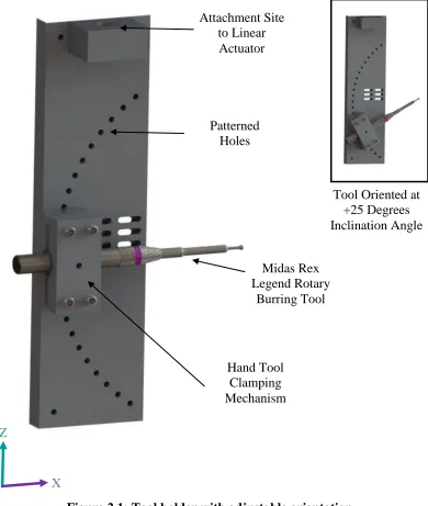
the circular pattern of holes depicted in Figure 2.1. These holes allow for an incremental
change in the inclination of the tool between -45° and 45° (5° increments). The diameter
of the circular pattern of holes align with the length of the burring tool; such that, at any
angle, the center of the end tooling bit remains stationary (Figure 2.1). Detailed drawings
of the fabricated components associated with the burring tool holder can be found in
Infrared Pyrometer
1 DOF Accelerometer Z
X
X
Z
Patterned Holes
Tool Oriented at +25 Degrees Inclination Angle Attachment Site
to Linear Actuator
Midas Rex Legend Rotary
Burring Tool
Hand Tool Clamping Mechanism
Figure 2.1: Tool holder with adjustable orientation
The Midas Rex Legend® rotary burring tool (Medtronic Inc, Minneapolis,
Minnesota) oriented at 0 degrees inclination and fastened in place on the tool holder
apparatus. An inset of the tool positioned at +25 degrees inclination is also shown to
2.2.2
Workpiece Positioning
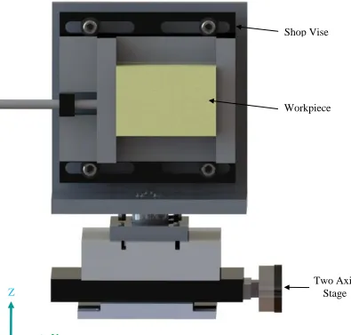
The workpiece positioning system was designed to maintain the workpiece in a fixed
spatial position with respect to the Instron frame (Figure 2.2). The primary component
ensuring the location, support as well as clamping of the prismatic samples was a
conventional tool shop vise. This allowed for the interchangeability of samples that could
be gripped in place using the vise.
To ensure that the workpiece was perpendicular to the feed rate of the tool; a series of
nuts were fastened between the vise and the aluminum back plate. The addition of nuts
between the vise and back plate allowed for the plane parallel to the workpiece face to be
dependent on the location of the nuts. Four lock nuts were then used to fasten the vise in
plane, locking any relative movement between the vise and tool.
The workpiece fixture was mounted on a two-axis stage which allowed for the depth of
cut and overlap of cut to be adjusted. Detailed drawings of the fabricated components
Workpiece Sample
6 DOF Load Cell
Z
Y
Y
Workpiece Shop Vise
Two Axis Stage
Figure 2.2: Workpiece positioning system with adjustable horizontal position
Z
The workpiece positioning system used a shop vise to clamp the workpiece in place.
A two axis stage was used to control the depth of cut and overlap of the burring
2.3
Measurement of Dependent Variables
2.3.1
Data Acquisition System
To ensure the correct time synchronization of all three measurands, all data collected by
the sensors was supplied to an USB-6210 data acquisition unit (National Instruments
Corporation, Austin, Texas) (Figure 2.3). The measurands were time stamped to allow for
simultaneous comparison of the signals. NI LabVIEW software was used for collection
and post-processing of the data that was sampled at 25 kHz for all transducers.
Specification sheets of the transducers can be found in Appendix B.
Temperature Sensing
Hardware
ATI Signal Conditioner ATI Mini 45 Load Cell
Endevco Accelerometer Endevco Signal Conditioner
Micro Epsilon Infrared Pyrometer
Micro Epsilon Signal Conditioner
NI USB-6210 Data Acquisition Unit
Three transducers (load cell, accelerometer, and infrared pyrometer) were used to
quantify the dependent variables. The transducers were integrated onto the tool holder
and workpiece apparatus and sampled via a NI-USB data acquisition unit.
2.3.2
Cutting Force Measurement
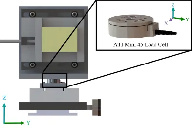
A three-axis load cell (Mini45, ATI Technologies, Markham, Ontario) with a resolution
of 1/16 N was used to acquire the triaxial components of the cutting force. The Mini 45
load cell was selected due to its suitable range (±145 N) associated with the burring
procedure as measured by previous studies and its ability to measure force in three planes
[41, 42, 46]. The load cell was instrumented between the workholding device and the
two-axis stage (Figure 2.4). A double Butterworth low pass filter of 10 Hz was applied on
the cutting force signal that was decimated at 1 kHz for post-processing purposes.
Six voltages supplied by the strain gauges instrumented within the load cell were sampled
by the data acquisition unit. A transformation matrix, supplied by the manufacturer, was
applied to the voltages to transform the voltages into forces. Forces in the X,Y, and Z
direction were recorded. The axis of the load cell are described by the following axis:
Z- direction: Parallel to feed direction of burring tool
X-direction: Normal to workpiece face