Adaptive Control Scheme of BLDC Drive Enhance
DSTATCOM Operation in Power Distribution System
MOOTHI SHAILAJA M-tech Student Scholar
Department of Electrical & Electronics Engineering, Scient Engineering College, Ibrahimpatnam;
Ranga Reddy (Dt); Telangana, India. Email:[email protected]
K. SREEPAL REDDY Assistant Professor
Department of Electrical & Electronics Engineering, Scient Engineering College, Ibrahimpatnam;
Ranga Reddy (Dt); Telangana, India. Email:[email protected]
Abstract: This concept proposes a hybrid control algorithm to maximize utilization and functionality of distribution static compensator (DSTATCOM). This control algorithm combines the different aspects of DSTATCOM operation and tries to mitigate the voltage and current harmonics, balance the source currents, improve the power factor, compensate for voltage disturbances such as sag and swell, reduce the losses and rating of inverter, and control the load power for energy conservation while analyzing their effects on the consumers. Moreover, at any time of operation, performance of proposed control algorithm based DSTATCOM is superior compared to its conventional counterparts. With all these advantages, proposed scheme provide a promising solution to enhance the operation of power distribution system. Detailed simulation results are presented to validate the performance of the proposed scheme. One of the main objectives of power distribution companies is to maintain load voltage within an acceptable voltage range while effectively managing the available power and load demand. The DSTATCOM is operated to maintain load voltage and pf within the pre-specified range based on the requirement.
The wind turbine acts as a prime-mover for doubly fed BLDC generator. To make the system stable, proper monitoring is required or sometimes an auxiliary system can also be a good option, which can support the primary system during undesirable conditions. The simulation results show a significant enhancement in shortening development time and improving dynamic performance of the BLDC motor compared to the conventional speed control of BLDC motor drive. The wind turbine acts as a prime-mover for doubly fed BLDC generator.
I INTRODUCTION
One of the main objectives of power distribution companies is to maintain load voltage within an acceptable voltage range while effectively managing the available power and load demand. During off peak load conditions (when power requirements are low) or during excess of available power, utilities try to operate the distribution system near to the maximum voltage rating of equipments. This forces consumers to operate their loads at more than the rated power. Consequently, it results in more electricity bills, more heating losses in the equipment,
and reduced equipment life. Again, during peak load conditions (high power demand), utilities operate the distribution system at the least possible voltage limit. Therefore, the load power in the present scenario is mostly on the goodwill of utility companies. Recently, few solutions have been proposed for energy conservation (also called conservation voltage reduction or CVR) at the consumer point by providing a step voltage change at the load point around its nominal voltage [1]. However, these devices have large initial cost and no proper mechanism to address the power quality (PQ) issues at the load point.
In a distribution system, voltage disturbances such as sag and swell are important PQ problems, which significantly affect the performance of sensitive loads, namely, process control industry, consumer related electronics equipment, adjustable-speed ac/dc drives, and healthcare equipment etc [2]. Distribution static compensator (DSTATCOM), a shunt custom power device connected at point of common coupling (PCC), has been utilized to compensate voltage disturbances by operating in voltage control mode (VCM) [3]–[10]. In this mode, DSTATCOM maintains the load voltage at a constant value, which is generally set to rated value (1.0 p.u). The DSTATCOM is highly effective in providing load voltage regulation; however, maintaining load voltage at rated value has several unwanted effects from customer point of view. With 1.0 p.u voltage at load point, DSTATCOM forces load to operate always at rated power. Hence, customers need to pay for constant power continuously, whereas rated heating losses will take place in the equipments for entire operation. Additionally, DSTATCOM needs to compensate for entire feeder drop for maintaining load voltage at 1.0 pu. It increases the filter current and results in increased power losses in inverter and feeder. Since, most of the consumer load can operate satisfactorily within the permissible range of its nominal voltage, it is not always necessary to operate DSTATCOM in VCM to maintain load voltage at 1.0 p.u.
related PQ problems [11], [12]. These result in distorted unbalanced source currents and non zero neutral current. Also, load voltages become unbalanced and distorted due to the flow of these currents through the feeder.
A DSTATCOM, operating in current control mode (CCM), supplies reactive and harmonic component of load currents to make source currents balanced, sinusoidal, and in phase with respective phase voltages [13]–[20]. It needs to be emphasized that, in the CCM operation of DSTATCOM, the load voltage follows the source voltage. Therefore, the load voltage and power are directly decided by the power distribution utilities. In addition to this, DSTATCOM in this mode of operation cannot compensate for voltage disturbances. Therefore, it is not useful during voltage disturbances and is disconnected from service. Further, unity power factor (UPF) is maintained at PCC in CCM operation. However, most of the utilities allow consumers to draw some reactive power at normal operation. Generally, consumers need not to pay for a certain power factor (pf) at the PCC (it varies with type of utilities and consumers). Hence, it is not compulsory to maintain UPF at the PCC while operating DSTATCOM in CCM.
The above discussion makes the point that both CCM and VCM operation of DSTATCOM have significant influence on the consumer load power and energy conservation. To the best of authors acknowledge, literature is not available to control the load power while effectively mitigating both current and voltage types of PQ problems based on their effects on consumers.
In this paper, a hybrid control scheme has been proposed to maximize the DSTATCOM utilization while considering the above mentioned issues. Instantaneous symmetrical component theory, with flexibility of choosing pf, is used to compute
reference source currents. The reference load voltages are computed such that the least allowable pf
is maintained at the PCC. Consequently, load power is appropriately controlled and advantages of energy conservation are also achieved. If reference load voltage at the predefined minimum pf comes less than the lowest allowable operating voltage, then pf is
improved to get new reference load voltage. Therefore, proposed scheme ensures that energy conservation is achieved while drawing allowable reactive power from the source. Moreover, load voltage is maintained at the constant value during voltage disturbances to protect the sensitive loads. Simulation results show that the proposed hybrid control algorithm based DSTATCOM can provide
energy conservation at load point in addition to mitigating current and voltage related PQ problems appropriately.
II SYSTEMDESCRIPTION
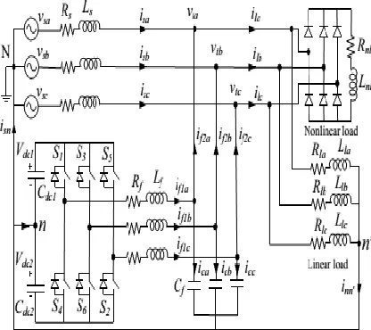
Circuit configuration of a DSTATCOM, as shown in Fig.3.1, is connected at the PCC in a three-phase four-wire distribution system.vsj, vtj, isj, and ilj are
source voltage, load voltage, source current, and load current respectively, where j=a, b, c represent phases. Rs and Xs represent the source impedance in three phases. The load consists of a diode rectifier feeding an RL load plus an unbalanced linear load. The DSTATCOM uses two-level, neutral-point-clamped VSI topology due to its ability to control the operation of each VSI leg independently. The dc link capacitors are represented by Cdc1 =Cdc2 = Cdc,
whereas the voltages maintained across them are Vdc1= Vdc2=Vdc=Vdcref. An LC filter is used at the
front end of VSI to achieve an appropriate output voltage at the PCC.
Fig 1 DSTATCOM configuration in a distribution system
III PROPOSED HYBRID CONTROL ALGORITHM
Objective of proposed hybrid control algorithm based DSTATCOM is to reduce the voltage and current harmonics, balance the source currents, improve the pf, compensate for voltage disturbances such as sag and swell, reduce the losses in VSI, reduce the rating of VSI, and control the load power for energy conservation while analyzing their effects on the consumers.
way that the penalty for reactive power drawn from the source is avoided. In literature, several reference generation schemes have been proposed. In this paper, instantaneous symmetrical component theory (ISCT) based algorithm is used for computation of reference source currents due to its flexibility in achieving desired pf [11]. Following three conditions are simultaneously satisfied while using ISCT based algorithm:
1. Source neutral current should be zero
(1) 2. A definite angle (φvi+) between fundamental
positive sequence load voltage and source current (vta1+ and ila1+respectively) is maintained.
Considering for phase-a
(2) 3. Source must supply average load power (Plavg)
and VSI losses (Ploss). Source power is given as
(3) where
(4)
Solving (3.1), (3.2), and (3.3) expressions for reference source currents are given as follows:
(5) Where
The phase-a load voltage and source current are given as follows:
(6) Phase-a source voltage is given as
(7) Applying Kirchhoff’s voltage law between source and load points
(8)
Fig2 Proposed hybrid control algorithm for reference load voltage generation
Using (6) and (7) in (8), we have
(9)
Where and
Equating real and reactive part in both the sides of above equation
(11) Finally, load voltage will be
(12)
With balanced supply, computed rms load voltage will be same for all three-phases and it will be used as Vt for further explanations. Once the
expression for load voltage from above equation is computed, reference load voltage magnitude for several DSTATCOM operating conditions will be developed. The flow chart of choosing the suitable reference load voltage is given in Fig.3.2 and explained as follows.
a) Source Voltage Is Less Than 0.9 Pu:
Voltage sag, which is most common voltage disturbance, is defined as the decrease in voltage from 0.9 pu to 0.1 pu for half cycle to one minute. Hence, if load voltage goes below 0.9 pu, then system experiences sag. During sag, primary aim of the compensator is to protect the load from this voltage disturbance. In conventional VCM operation of DSTATCOM, load voltage is maintained at 1.0 pu during sag. It results in more current injection by the VSI, increased losses in VSI, and rated power drawn by the load. In this paper, the reference load voltage is set at 0.9 pu during voltage sag. At this voltage, following features are obtained
i. Load will remain operational even during voltage disturbances.
ii. Load will draw minimum power, as compared to rated power in conventional DSTATCOM operating in VCM.
iii. Filter current will less compared to conventional VCM operation. Hence, VSI losses will decrease and so, efficiency will increase. Moreover, size of VSI can be reduced due to reduced current requirement.
b) Source Voltage Is Greater Than 0.9 Pu:
When source voltage is greater than 0.9 pu, then it is necessary to find appropriate reference load voltage. Conventional CCM operation of DSTATCOM maintains UPF at the PCC. Usually, most of the utilities permit customers to draw allowable reactive power without paying for tariff (however, it may vary depending upon customers). Therefore, from customer point of view, it is not necessary to maintain UPF at PCC. In proposed scheme, we have considered that the customers are allowed to operate load up to 0.9pfwithout any penalty. Keeping this into account, reference source currents are calculated using instantaneous symmetrical component theory at a pf of 0.9. i.e., β= 0.28. With this source current,
load voltage is calculated using (3.12). At this voltage, following conditions are possible:
1) Vta is Less Than 0.9 pu: This voltage is computed
at the lowest permissible value of pf. But,
improvement in pf will increase the load voltage. Therefore, pf is improved in a fixed step of 0.05 from previous value of 0.9 pu and modified reference source currents are again computed using (5). For this current, modified load voltage is computed. If this voltage becomes greater than 0.9 pu then same voltage is used as reference load voltage. This method gives following advantages:
i. Source currents will be balanced and sinusoidal. ii. Reduced currents are supplied by the filter compared to conventional CCM operation. Therefore, VSI losses decrease and its efficiency increases. iii. Load voltage is lesser compared to conventional CCM operation. Hence, power drawn by the load will decrease. It will reduce the power tariff, reduce the heating loss, and increase the device life.
However, if the load voltage is not more than 0.9 pu, then above process is repeated until the load voltage becomes more than 0.9 pu. But, there must be a limit on the value Of pf that can be
achieved. Our objective is to keep load operational by keeping load voltage within the permissible range, while ensuring that allowable amount of reactive current is also drawn from the source. Importantly, load voltage will be more as compared to conventional CCM operation if pf is set to leading. It will force load to draw additional real power. Therefore, maximum pf is limited to 1.0. If load
voltage does not become greater than 0.9 pu with this pf, then a flat voltage of 0.9 pu is set as reference load
voltage.
2) Vta is Less Than 1.0 pu: This is the normal operating conditions as load voltage lies between 0.9 pu to 1.0 pu, where system operates most of the time. The reference load voltage is set at a value obtained from (12). This voltage will indirectly control the source currents and maintains 0.9 pf at the PCC.
Therefore, operation of proposed scheme in this case will be similar to conventional CCM operation of DSTATCOM. However, following additional advantages are achieved in proposed scheme:
i. Predefined minimum pf is maintained at the PCC
by the compensator. Hence, filter currents are reduced. Consequently, VSI losses decreases and its efficiency increases.
ii. The least pf at PCC makes load voltage lesser
3) Vta is Greater Than 1.0 pu: Maintaining load voltage at a value greater than 1.0 pu forces load to draw more power than the rated power. Further, filter will have to supply more reactive current to maintain this voltage. If load voltage comes more than 1.0 pu, then source voltage is also more than 1.0 pu. This voltage is computed at a pf of 0.9. If load
voltage does not become less than 1.0 even for 0.9pf, a flat voltage of 1.0 is set as reference voltage. In this case, performance of DSTATCOM and load in proposed scheme will be same as that of conventional DSTATCOM operating in VCM.
IV BLDC MOTOR
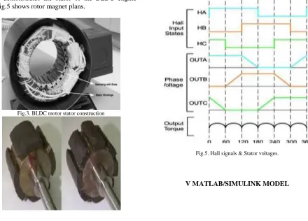
BLDC engine comprises of the perpetual magnet rotor and an injury stator. The brushless engines are controlled utilizing a three stage inverter. The engine obliges a rotor position sensor for beginning and for giving legitimate compensation arrangement to turn on the force gadgets in the inverter extension. In light of the rotor position, the force gadgets are commutated consecutively every 60 degrees. The electronic compensation takes out the issues connected with the brush and the commutator plan, in particular starting and destroying of the commutator brush course of action, along these lines, making a BLDC engine more rough contrasted with a dc engine. Fig.4 demonstrates the stator of the BLDC engine and fig.5 shows rotor magnet plans.
Fig.3. BLDC motor stator construction
Fig.4. BLDC motor Rotor construction.
The brush less dc engine comprise of four fundamental parts Power converter, changeless magnet brushless DC Motor (BLDCM), sensors and control calculation. The force converter changes power from the source to the BLDCM which thus changes over electrical vitality to mechanical vitality. One of the remarkable highlights of the brush less dc engine is the rotor position sensors, in view of the rotor position and order signals which may be a torque charge, voltage summon, rate order etc; the control calculation s focus the entryway sign to every semiconductor in the force electronic converter.
The structure of the control calculations decides the sort of the brush less dc engine of which there are two principle classes voltage source based drives and current source based drives. Both voltage source and current source based commute utilized for perpetual magnet brushless DC machine. The back emf waveform of the engine is demonstrated in the fig. 6. Be that as it may, machine with a non sinusoidal back emf brings about diminishment in the inverter size and lessens misfortunes for the same influence level.
Fig.5. Hall signals & Stator voltages.
Fig 6 Matlab/simulation circuit of without DSTATCOM configuration in a distribution system.
Fig 7 simulation wave form of without compensation of output source voltage and current
Fig 8 simulation wave form of without compensation of output load current
Fig 9 Matlab/simulation circuit of with DSTATCOM configuration in a distribution system.
Fig 10 simulation wave form of source voltage and current
Fig 11 simulation wave form of dc voltage
Fig 12 simulation wave form of filtering voltage
Fig 13 simulation wave form of load filter voltage
Fig 14 simulation wave form of source side power factor
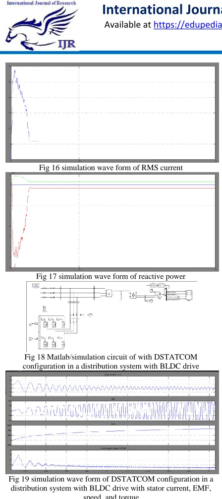
Fig 16 simulation wave form of RMS current
Fig 17 simulation wave form of reactive power
Fig 18 Matlab/simulation circuit of with DSTATCOM configuration in a distribution system with BLDC drive
Fig 19 simulation wave form of DSTATCOM configuration in a distribution system with BLDC drive with stator current, EMF,
speed, and torque
V CONCLUSION
This paper has proposed a hybrid control algorithm to maximize utilization and functionality of conventional DSTATCOM. Unlike conventional CCM and VCM operations, the DSTATCOM is operated to maintain load voltage and pf within the
pre-specified range based on the requirement. In normal operation, load voltage is regulated such that the least allowable pf is maintained at the PCC while making source currents balanced and sinusoidal. During voltage sag, load voltage is maintained at minimum value needed to keep load operation satisfactorily. The proposed method provides a promising solution to enhance the operation of power
distribution system. This scheme not only provides several PQ improvement features but also reduces load real and reactive power, filter current requirement to achieve desired compensation performance, and leads to reduction in the size of VSI. Extensive simulation studies validate effectiveness of the proposed BLDC drive to study the characteristics, and to achieving good performance.
REFERENCES
[1] [Online]. Available:
http://legendpower.com2013
[2] M. H. Bollen, Understanding power quality problems. vol. 3, IEEE press New York, 2000.
[3] H. Fujita and H. Akagi, “Voltage-regulation performance of a shunt active filter intended for installation on a power distribution system,” IEEE Trans. Power Electron., vol. 22, no. 3, pp. 1046–1053, May 2007. [4] Chandan Kumar and Mahesh K. Mishra, “A
multifunctional DSTATCOM operating under stiff source,” IEEE Trans. Ind. Electron., vol. 61, no. 7, pp. 3131–3136, Jul. 2014.
[5] A. Jain, K. Joshi, A. Behal, and N. Mohan, “Voltage regulation with STATCOMs: modeling, control and results,” IEEE Trans. Power Del., vol. 21, no. 2, pp. 726–735, Apr. 2006.
[6] Mahesh K. Mishra, A. Ghosh, and A. Joshi, “Operation of a DSTATCOM in voltage control mode,” IEEE Trans. Power Del., vol. 18, no. 1, pp. 258–264, Jan. 2003.
[7] Y.-R. Mohamed and E. El-Saadany, “A control scheme for pwm voltage source distributed-generation inverters for fast load-voltage regulation and effective mitigation of unbalanced voltage disturbances,” IEEE Trans. Ind. Electron., vol. 55, no. 5, pp. 2072–2084, May 2008.
[8] R. Gupta, A. Ghosh, and A. Joshi, “Performance comparison of VSC based shunt and series compensators used for load voltage control in distribution systems,” IEEE Trans. Power Del., vol. 26, no. 1, pp. 268– 278, Jan. 2011.
system,” IEEE Trans. Power Electron., vol. 25, no. 1, pp. 95–104, Jan. 2010.
[10] R. Gupta, A. Ghosh, and A. Joshi, “Multiband hysteresis modulation and switching characterization for sliding-mode-controlled cascaded multilevel inverter,” IEEE Trans. Ind. Electron., vol. 57, no. 7, pp. 2344– 2353, Jul. 2010.
[11] A. Ghosh and A. Joshi, Power Quality Enhancement Using Custom Power Devices. Kluwer Publications, 2002.
[12] S. Rahmani, A. Hamadi, K. Al-Haddad, and L. Dessaint, “A combination of shunt hybrid power filter and thyristor-controlled reactor for power quality,” IEEE Trans. Ind. Electron., vol. 61, no. 5, pp. 2152–2164, May 2014.
[13] A. Bhattacharya, C. Chakraborty, and S. Bhattacharya, “Parallel connected shunt hybrid active power filters operating at different switching frequencies for improved performance,” IEEE Trans. Ind. Electron., vol. 59, no. 11, pp. 4007–4019, Nov. 2012. [14] S. Rahmani, A. Hamadi, and K. Al-Haddad,
“A Lyapunov-functionbased control for a three-phase shunt hybrid active filter,” IEEE Trans. Ind. Electron., vol. 59, no. 3, pp. 1418–1429, Mar. 2012.
[15] A. Bhattacharya and C. Chakraborty, “A shunt active power filter with enhanced performance using ANN-based predictive and adaptive controllers,” IEEE Trans., Ind. Electron., vol. 58, no. 2, pp. 421–428, Feb. 2011.
[16] P. Kanjiya, V. Khadkikar, and H. Zeineldin, “A noniterative optimized algorithm for shunt active power filter under distorted and unbalanced supply voltages,” IEEE Trans. Ind. Electron., vol. 60, no. 12, pp. 5376– 5390, Dec. 2013.
[17] H. Hu, W. Shi, Y. Lu, and Y. Xing, “Design considerations for DSP controlled 400 Hz shunt active power filter in an aircraft power system,” IEEE Trans. Ind. Electron, vol. 59, no. 9, pp. 3624–3634, Sep. 2012.
[18] B. Singh and S. Arya, “Back-propagation control algorithm for power quality improvement using DSTATCOM,”IEEE Trans. Ind. Electron., vol. 61, no. 3, pp. 1204–1212, Mar. 2014.
[19] H. Akagi and R. Kondo, “A transformer less hybrid active filter using a three-level pulse width modulation (PWM) converter for a medium voltage motor drive,” IEEE Trans.
Power Electron., vol. 25, no. 6, pp. 1365– 1374, Jun. 2010.