Available online: https://edupediapublications.org/journals/index.php/IJR/ P a g e | 1707
Cement-Based Microstructure Implications on : Electrical Current Flow
and Cement Hydration
Satyashiva Prasad Nannuta & Vijay Gundala
Assistant Professor Dept of Civil, Balaji Institute of Technology & Science
Abstract
Stray current is an electrical current "spillage" from metal transmitters and electrical establishments. When it moves through bond based materials, electrical vitality is changed over to warm vitality that causes expanding temperature because of Joule warming wonders. The point of this paper is to reveal insight into the impact of electrical current stream on bond hydration, warm properties and pore structure changes of concrete based materials. Calorimetry tests demonstrate that level of concrete hydration increments as an aftereffects of temperature increment because of electrical current course through bond based materials. To assess the impact of electrical current on the warm properties of concrete glue, the particular warmth of bond glue was figured in view of the level of bond hydration and temperature improvement amid the hydration procedure. MIP tests were done to evaluate changes in the pore structure because of electrical current stream. The outcomes demonstrates that if no different elements are available, filtering is kept away from and for moderately early concrete hydration age, the electrical current stream quickens bond hydration ,leading to an underlying lessening in porosity of the bond paste.
Index Terms
—cement hydration, stray current, Joule heating, temperature, microstructureI. INTRODUCTION
Cement hydration plays a critical role in the small scale basic improvement of concrete based materials. Concrete hydration is a complex
exothermic concoction process, incorporating a few stages which are connected to the commitment of various clinker minerals. The hydration procedure displays a progression of synthetic and physico-concoction responses, joined by warm age and warmth development, which rely upon concrete structure, bond fineness, and surrounding temperature as principle factors [1], [2]. This procedure is a change from a high vitality state to a lower one, where the vitality is transmitted as warmth [3]. Amid the concrete hydration process, temperature ascends because of the warmth of bond hydration, which can be measured utilizing e.g. thermocouples. Temperature is an imperative parameter which altogether influences materials properties and execution at early age, for example, quality [4], [5], warm anxiety [6] and trouble (i.e. splitting) [7], [8]. The temperature improvement in a bond based just affected by the previously mentioned inward factors yet in addition identified with outer components (i.e. encompassing condition, stray current stream and so forth.). Stray current can stream in the encompassing medium through conductive ways and can along these lines likewise move through concrete and strengthened solid structures.
Available online: https://edupediapublications.org/journals/index.php/IJR/ P a g e | 1708 respectability of strengthened concrete as a
worldwide framework. In this way, stray current-related wonders with significance to both steel and solid mass properties are of high significance as for the administration life of common structures. Stray current sources can be "provided" from outside Cathodic Protection (CP) establishments, DC travel frameworks (e.g. charged railroads, tram frameworks, streetcars, welding operations, individuals movers), high voltage DC and electrical power transmission frameworks. Stray ebb and flow has a tendency to "enter" materials with low electrical protection, for example, steel/fortified solid structures, water or gas pipeline, link sheaths and some other covered metal establishments. The impact of stray current relies upon the level of the subsequent current thickness. It has been accounted for that electrical current (counting stray current) has negative impact on bond based materials, for example:
1) stray current can start and upgrade steel erosion [9];
2) stray current adjusts microstructural properties of mortar and solid mass network [10]-[12]; 3) stray current affects the corruption forms in concrete based frameworks As far as lessening in mechanical properties and expanded penetrability. In the interim, the impacts of electrical current stream can be likewise positive at beginning states e.g. for quality advancement of concrete based materials as inside electrical curing application [13]-[16]. Among different impacts, the electrical vitality, as created from stray current stream, believers to warm vitality, known as Joule Heating, and results in temperature ascend in bond based materials. The level of temperature rise is sed framework isn't relative to the square of the electrical present, coursing through the framework [17]. The temperature ascend, as created by stray current stream, can possibly build the rate of concrete hydration and thusly brings about microstructural changes of the mass bond based grid e.g. changed
porosity, porousness, basic pore estimate. In any case, the impact of stray current stream on the hydration procedure and microstructural advancement of bond based materials isn't surely knew. In light of a progression of exploratory outcomes, the point of this work is to decide an "electrical upgrade" factor, which was additionally utilized as the relationship between's temperature rise and electrical current move through bond based materials. A recreation way to deal with foresee the temperature rise and in this manner modified bond hydration was utilized. The reproduction approach, utilizing HYMOSTRUC3D, was approved through the recorded exploratory information (e.g. isothermal calorimetry tests). Moreover, mercury interruption porosimetry (MIP) tests were led to measure pertinent micro structural changes (porosity and pore structure) due to electrical current flow.
II. EXPERIMENTAL MATERIALS AND
METHODS
A. Materials
Series A:
Cement paste and mortar prisms of 55 mm x 55 mm x 295 mm (Fig. 1a) were cast, using OPC CEM I 42.5N with water-to-cement ratio of 0.5 and cement-to-sand ratio of 1:3 for the mortar. The chemical composition (in wt. %) of CEM I 42.5N (ENCI, NL) is as follows: 63.9% CaO; 20.6% SiO2; 5.01% Al2O3; 3.25% Fe2O3; 2.68% SO3; 0.65% K2O; 0.3% Na2O. The specimens were maintained in semi-adiabatic conditions after casting and for the total test duration of 4 days. These specimens were used to monitor temperature alterations within cement hydration, with or without stray current involved, through embedded thermocouples.
Available online: https://edupediapublications.org/journals/index.php/IJR/ P a g e | 1709 Another group of mortar specimens i.e. mortar
cubes of 40mm x 40 mm x 40 mm (Fig. 1b) were cast in the same manner and mix design. They were maintained in sealed conditions for test duration of 112 days. The mortar cubes were subjected to some of the lower current density regimes (as specified further below)
Series C:
Cement paste, w/c ratio 0.35 and 0.5 with weight cast for isothermal calorimetry test.
B. Sample Designation
1) Series A – specimens with embedded thermocouples:
Two main groups of specimens were investigated:
1) Control (reference) group - no DC current involved and
2) Stray current group with subgroups, reflecting the level of DC current involved
i.e. groups “1 A/m2”, “10 A/m2”, “40 A/m2”, and “60 A/m2”. The set-up for DC current application is as depicted in Fig. 1a.
2) Series B – sealed mortar cubes: the specimens were presented by three sub-groups:
1) control group - no DC current involved;
2) group “100 mA/m2” and
3) group “1A/m2” (Fig. 1b).
3) Series C – cement paste used for isothermal calorimetry tests:
The tests were performed on three groups of samples: control group, “10 mA/m2”, “100 mA/m2” and “1A/m2” group. The experimental set up of calorimetry tests is presented in Fig. 2.
Figure1. Experimental set-up for measurements of temperature increase in cement paste and mortar specimens due to electrical current flow (Series A) (a) and experimental set up of electrical current flow
Available online: https://edupediapublications.org/journals/index.php/IJR/ P a g e | 1710
Figure 2. (a) Isothermal calorimeter (TAM-Air-314) used to measure heat release of cement paste;(b) Schematic pictures of the holders for “under current” regime (Series C).
(C). Current Regime
A recreation of stray current was accomplished by applying a DC current at the level of "1 A/m2", "10 A/m2", "40 A/m2", and "60 A/m2". For the examples in Series An, a negative and a positive terminal were associated with a 80 V source. The present thickness levels were balanced by extra resistors. The applicable surface territory was computed in light of the geometry of the examples, basically the cross area An (i.e. A=55 mm x 55 mm). Thermocouples were put quickly subsequent to throwing of the concrete glue (and mortar) to record naturally the temperature improvement by associating with the AC/DC converter and the (PC). For the examples in Series B, DC current was connected with level of 100mA/m2 and 1A/m2. For the examples in Series C, DC current was connected with level of 10mA/m2, 100mA/m2 and 1A/m2.
D. Isothermal Calorimetry Tests
Warmth advancement and rate of hydration of concrete glue were measured by Thermometric isothermal conduction calorimeter (TAM-Air-314, a 8-channel warm stream calorimeter). The example arrangement and test strategy took after understood philosophy [18], with the exception of the adjustments identified with the application
andmonitoring the impact of electrical current stream. For the "under current" examples, an indistinguishable ampoules from for the control cases were utilized, yet composed in an approach to incorporate two metal terminals as electrical current channels (schematic pictures in Fig. 2b). Electrical current was connected quickly
after samples’ casting from an external source for about 7 days.
E. Temperature Development
To simulate stray current, an electrical field was applied to the cement-based specimens (paste and mortar prisms) immediately after casting and until approximately 4 days of age. The temperature increase due to both cement hydration and electrical current flow were measured for the specimens in Series A, using thermocouples, embedded in the middle, right and left sections of the specimens (Fig. 1a).
F. Mercury Intrusion Porosimetry (MIP)
[19]-Available online: https://edupediapublications.org/journals/index.php/IJR/ P a g e | 1711 [21], i.e. drying treatment to removes of water
from the sample before mercury pressure is applied. For isothermal calorimetry tests, MIP was conducted for cement paste at hydration age of 7 days.
G. Compressive Strength
The specimens from Series B – mortar cubes – were subjected to compressive strength tests, recorded at 3, 7, 28, and 112 days. Hereby reported are the results for hydration ages 4, 8, 29, and 113 days as relevant to this work
III. RESULTS AND DISCUSSION
A. Degree of Cement Hydration
Based on the isothermal heat of hydration that was derived from integration of the rate of heat evolution, the degree of hydration at time t can be calculated using the following equation [22], [23]:
(1) where Q(t) is the heat liberated at time t (J/g), Qmax is the maximum amount of heat liberated at complete hydration (J/g).Due to electrical current flow through the specimens, maximum amount of heat liberated at complete hydration is calculated as follows:
(2)where is maximum heat of hydration of Portland cement at complete hydration (J/g), is the maximum amount of heat liberated by electrical current flow at complete hydration cem Q el Qm ax Calculation of maximum heat of hydration of Portland cement cem
Qm ax max) ( Q t Q el Qcem Q Q
(3) where q1..q6 are the heat of hydration of the constituents considered. The maximum amount of heat liberated by electrical current flow can be el Qm ax
(4) where I is the electrical current flow (in Ampere), R is the resistance of cement (in
the mass of cement (in kg).
Fig. 3 reveals the effect of electrical current flow on the heat release and the degree of hydration of cement paste, determined by isothermal
Available online: https://edupediapublications.org/journals/index.php/IJR/ P a g e | 1712 Figure 3. Heat released (a) and degree of hydration (b) as function of time for cement paste with w/c 0.5 and 0.35.
Figure4. Temperature increase as function of electrical current density (a)and rate constant as function of electrical current density (b) in cement paste compared to control specimens.
Generally, the degree of cement hydration for w/c ratio 0.35 is slightly higher at early age and up to about 42 hours. After this period, slightly lower values were recorded, from 42 hours to the end of the test, compared to results in specimens of w/c ratio 0.5. The higher degree of cement hydration for specimens of w/c ratio 0.5 at the later ages, compared to these of w/c ratio 0.35, is a consequence from the larger amount of water available for cement hydration. This results in more space, available for the dissolution of reactants, nucleation and precipitation of hydration products, as stated by Bentz [24], [25]. At higher temperature, the degree of hydration initially develops faster but
ends up with lower ultimate values at later stages [26]-[28] – a result, also confirmed through the dt RI c mel QB. Rate of Cement Hydration in Condition of Stray Current Flow The rate of cement hydration was derived from the Arrhenius equation:
Figure 5
Available online: https://edupediapublications.org/journals/index.php/IJR/ P a g e | 1713 current flow at T2 which is the temperature
increase due to electrical current flow.
Based on the relationship between temperature and the specific reaction velocity, it is possible to calculate the rate of hydration in cement-based materials due electrical current flow (Eq. (5)). In the temperature range above 20°C, the activation energy (Ea) for ordinary Portland cement may be assumed to be 33.500J/mol [29] By solving Eq. (5), it follows that at w/c ratio 0.35 the increase of temperature is from 21.29 °C, to 21.42 °C, 21.55 °C (due to application of electrical current with level current density 10 mA/m2, 100 mA/m2 and 1A/m2, respectively). This means increase of hydration rate by factor of 1.056, 1.064, and 1.070, respectively (see Fig. 4b). Whereas for w/c ratio 0.5, the increase of temperature is from 21.25 °C, 21.38 °C, 21.54 °C (Fig.4a), increasing hydration rate by factor of 1.054, 1.062, and 1.068, respectively (see Fig. 4b). It can be seen in Fig. 4b that the rate of cement hydration strongly depends on the level of electrical current and the w/c ratio.
C. Pore Structure of Cement Paste
Fig. 5 depicts the porosity changes (derived from MIP) of cement paste due to electrical current flow. As shown in Fig. 5, total porosity is reduced with increasing the level of electrical current and with lowering the w/c ratio. In the case of “under current” regimes, the hydration products would be formed faster, surrounding the hydrating cement particles, resulting in a denser gel due to a larger amount of hydration product. In other words, the porosity of cement paste decreases with increased percentage of hydration products. For “under current” regimes with w/c ratio 0.35, the total porosity decreased to 0.55%, 2.61%, and 4.26% for current density levels of 10mA/m2, 100mA/m2 and 1A/m2, respectively, compared to control specimens. For specimens of w/c ratio 0.5, these numbers
are slightly smaller i.e. 0.53%, 2.34%, 3.41%, respectively. This different effect may be caused by the fact that higher w/c ratio would results in a higher total porosity as pointed out by Odler et al. [30] and confirmed by other authors [31]-[33]. Total porosity development of cement paste.
The influence of electrical current flow on temperature increase in cement paste and mortar was simulated by employing various already reported equations [34]: the electrical current flow through cement paste (and mortar) increases the temperature development due to resistive heating, or Joule heating effect, resulting in accelerating the rate of cement hydration. In HYMOSTRUC3D, the penetration rate of the reaction front for an individual cement particle at time t is computed with the following basic rate formula [22].
(6) where Ko(.) is the basic rate factor The influence of electrical current flow on temperature increase in cement paste can be incorporated through temperature functions in
the Arrhenius function that quantifies the effect of the curing temperature T on the rate penetration of reaction front in an individual cement particle:
(7) where R is the gas constant (8.31 103 kJ/mol.K), A is the constant and AE is the activation energy.Whereas F2 is accounted for the effect of temperature-induced morphological and structural changes that can be represented by the following equation:
(8) 78 International Journal of Structural and Civil Engineering Research Vol. 6, No. 2, May 2017 © 2017
Available online: https://edupediapublications.org/journals/index.php/IJR/ P a g e | 1714 To determine an appropriate model for
temperature rise in condition of electrical current flow, curve fitting from experimental data were performed using log normal distribution function as follows:
(9) where To is the initial temperature (°C), A is the constant, J is the electrical current density (A/m2), Ju is the unit of electrical current density (A/m2
IV. SIMULATION RESULTS AND
DISCUSSION
In this section, simulation of the hydration of Portland cement with four-phase concept is discussed and validated with experimental results. The size of the simulated cubic cement
Eq. (9) an approximated relationship between the applied electrical current density and the temperature development of cement paste, as given in the Fig. 6, can be derived. Furthermore, from Eq. (9) the level of current density, able to substantially increase the temperature and therefore to possibly create internal damage can be predicted, which is as aforementioned at
temperatures higher than
effects of the current flow, the corresponding electrical current density value is 300A/m2 (derived by solving of Eq. (9)). This means that when electrical current flow through the cement paste is higher than 300 A/m2, the maximum temperature increase in cement paste is higher
damage is high.
A. Effect of Low Level Current Density (≤ 1A/m2) on Degree of Cement Hydration
Available online: https://edupediapublications.org/journals/index.php/IJR/ P a g e | 1715 Figure 6. Relationship between applied electrical current density and temperature development of cement paste.
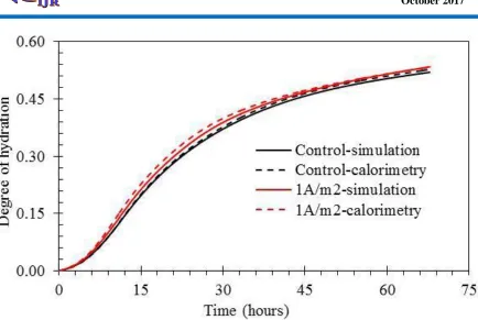
Figure 7. Simulation of degree of hydration as function of time for cement paste with w/c 0.5 and validation with experimental data from calorimetry tests.
As seen in the Fig. 7, 1A/m2 current density is enough to accelerate the degree of cement hydration compared to control specimens, even if the temperature rise due to electrical current flow is quite small - about 1.54°C from 20 °C to 21.54 °C (Fig. 4a). The simulation results have a good agreement with experimental results (Fig.
7). For example, the accelerated cement hydration in condition of stray current flow was confirmed by MIP tests (Fig. 5).
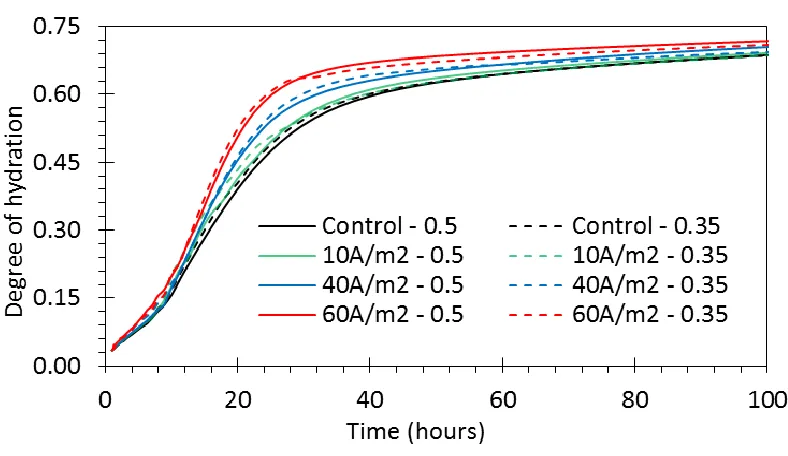
Available online: https://edupediapublications.org/journals/index.php/IJR/ P a g e | 1716 The simulation results in Fig. 8 show that degree
of hydration of cement paste for w/c ratio 0.35 tends to have higher values at early age but lower values at later age compared to w/c ratio 0.5 (Fig. 8). This is due to the fact that less water in the low water to cement ratio will be heated by electrical current flow faster, resulting in accelerated kinetics of cement hydration at early age. However, specimens with higher w/c ratio (i.e. 0.5) generally exhibit a higher degree of hydration than the lower w/c ratio (i.e. 0.35) at later age as also stated by Bentz [35]. As has been mentioned earlier, this is due to the larger volume of water, available for cement hydration
at higher w/c ratios. Furthermore, it can be seen, Fig. 8, that the degree of cement hydration increases as the intensity/level of electrical current flow increases.
Available online: https://edupediapublications.org/journals/index.php/IJR/ P a g e | 1717
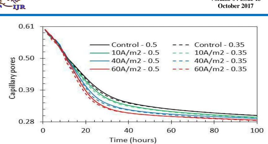
Figure 9. Capillary pores development of cement paste in condition of electrical current flow as function of time
Fig. 9 reveals capillary pores development of cement paste in condition electrical current flow as function of time. The results are derived from the HYMOSTRUC3D simulation. Generally, porosity decreases as the hydration proceeds. In addition, the porosity of a paste with lower level electrical current flow is greater than the porosity of the same paste with higher level electrical current. Similar results were obtained from Goto et al. study [36] in which they investigated the effect of w/c ratio (i.e. 0.35, 0.40, 0.45) and temperature (i.e 27°C and 60°C) on total porosity of a cement paste at 28 days. However, the hydration proceeds, the effect of electrical current flow on porosity becomes less evident because the effect of electrical current flow on the ultimate degree of hydration is small (see Fig. 8).
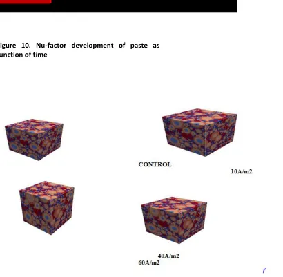
C. Nu-Factor
-factor development of -factor gives the ratio between volume of the reaction products and volume of the reactant.
As seen in the Fig. 10 the nu-factor of paste gradually decreases with increasing the electrical
Available online: https://edupediapublications.org/journals/index.php/IJR/ P a g e | 1718
Figure 10. Nu-factor development of paste as function of time
Available online: https://edupediapublications.org/journals/index.php/IJR/ P a g e | 1719 D. Virtual 3D Microstructure
In order to quantify the influence of electrical current flow on the hydration products of cement paste, HYMOSTRUC3D simulations were performed. Figure 11 shows the virtual 3D microstructure of hydrated cement paste at different levels of current density with two different water-to-cement ratio (i.e. 0.5 and 0.35). Fig. 11 presents the simulation for w/c ratio 0.5 only. The dimension of the simulated 3D volume of cement paste microstructure is
due to electrical current flow was already experimental recorded. This leads to re-distribution of hydration products in the cement paste. The modelled microstructure of cement paste, hardly changes at levels of electrical current, lower than 60 A/m2 Control 10A/m2 40A/m2 60A/m2(Fig. 11). There was no significant difference of hydration products distribution. At the level 60A/m2, accelerated cement hydration was already more obvious. The simulation results are well in line with the experimentally derived results. Therefore, the employed numerical simulation can be further employed to derive microstructural changes in the presence of significantly larger current density levels.
CONCLUSIONS
This paper deals with the influence of electrical current flow on cement hydration and micro structural changes of cement paste. The experimental results were coupled to simulation of the process of hydration. The following conclusions can be drawn:
1. Temperature increase due to electrical current flow accelerates cement hydration, leading to increase in the amount of hydration products in the cement paste. The level of temperature increase is proportional to the square of electrical current flow in the cement-based materials.
2. Temperature increase in cement-based materials due to electrical current and its effect on performance depend on several factors, as follows:
a) initial properties of the cement paste (e.g. w/c ratio);
b) cement content;
c) level of the electrical current flow;
3. The specific heat of cement paste decreases with increasing the level of electrical current flow and with increasing the w/c ratio.
4. Numerical simulation of the hydration process is well in line with the experimental results and can be employed further to elucidate similar mechanisms in various conditions as different w/c ratio or higher current density levels.
REFERENCES
[1] P. C. Hewlet, Lea’s Chemistry of Cement and Concrete, 4th ed. Oxford: Butterworth-Heinemann, 2004.
[2] H. F. P. Taylor, Cement Chemistry, 2nd ed. London: Thomas Telford, 1997.
[3] S. Mindess, J. F. Young, and D. Darwin, Concrete: Prentice-Hall, Upper Saddle River, New Jersey, USA, 2003.
[4] W. M. Hale, T. D. Bush, B. W. Russell, and S. F. Freyne, “Effect of curing temperature on hardened concrete properties,” Transportation Research Record: Journal of the Transportation Research Board, no. 1914, pp. 97–104, 2005.
Available online: https://edupediapublications.org/journals/index.php/IJR/ P a g e | 1720 Dissertation, Polytechnic University, Brooklyn,
New York, 1988.
[6] H. T. Yu, L. Khazanovich, M. I. Darter, and A. Ardani, “Analysis of concrete pavement responses to temperature and wheel loads measured from instrumented slabs,” Transportation Research Record, no. 1639, pp. 94–101, 1998.
[7] T. Nishizawa, T. Fukuda, S. Matsuno, and K. Himeno, “Curling stress equation for transverse joint edge of a concrete pavement slab based on finite-element method analysis,” Transportation Research Record, no. 1525, pp. 35–43, 1996.
[8] A. R. Mohamed and W. Hansen, “Effect of nonlinear temperature gradient on curling stress in concrete pavements,” Transportation Research Record: Journal of the Transportation Research Board, no. 1568, pp. 65–72, 1997.
[9] L. Bertolini, M. Carsana, and P. Pedeferri, “Corrosion behaviour of steel in concrete in the presence of stray current,” Corrosion Science, vol. 49, pp. 1056-1068, 2007.
[10] D. A. Koleva, J. H. W. de Wit, K. van Breugel, L. Veleva, E. P. M. van Westing, O. Copuroglu, and A. L. A. Fraaij, “Correlation of microstructrure, electrical properties and electrochemical phenomena in reinforced mortar. Breakdown to multi-phase interface structures. Part II: Pore network, electrical properties and electrochemical response,” Materials Characterization, vol. 59, pp. 801-815, 2008.
[11] D. A. Koleva, K. van Breugel, and J. H. W. de Wit, “The effect of electrical current flow, as a simulation of cathodic prevention, on early hydration rate and microstructure of
cement-based materials,” European Federation of Corrosion, no. 299, 2008.
[12] A. Susanto, D. A. Koleva, and K. van Breugel, “DC current-induced curing and ageing phenomena in cement-based materials,” in Proc. 1st International Conference on Ageing of Materials and Structures, Delft: Ageing Center TU Delft, pp. 562-568, 2014.
[13] S. Bredenkamp, D. Kruger, and G. L. Bredenkamp, “Direct electric curing of concrete,” Magazine of Concrete Research, vol. 45, no. 162, pp. 71-74, March 1993.
[14] L. Heritage, “Direct electric curing of mortar and concrete,” Napier University, Edinburgh, UK, 2001.
[15] G. W. John and K. G. Narendra, “Equipment for the investigation of the accelerated curing of concrete using direct electrical conduction,” Measurement, vol. 35, pp. 243–250, 2004.
[16] J. G. Wilson and N. K. Gupta, “Analysis of power distribution in reinforced concrete during accelerated curing using electroheat,” IEE Proceedings–Electric Power Applications, vol. 143, no. 2, pp. 172–176, 1996.
[17] A. von Meier, Electric Power Systems: A Conceptual Introduction, p. 67, 2006, John Wiley & Sons, USA.
[18] L. Wadso, “An experimental comparison between isothermal calorimetry, semi-adiabatic calorimetry and solution calorimetry for the study of cement hydration,” NORDTEST Report 522, 2003.
Available online: https://edupediapublications.org/journals/index.php/IJR/ P a g e | 1721 (previous) concrete,” ACI Materials Journal, vol.
106, no. 5, pp. 429-438, 2009.
[20] J. Hu, “Porosity of concrete, morphological study of model concrete,” PhD thesis, Delft University of Technology, Delft 2004.
[21] G. Ye, “Experimental study and numerical simulation of the development of the microstructure and permeability of cementitious materials,” Ph.D. thesis. Delft: Delft University of Technology, 2003.
[22] K. van Breugel, “Simulation of hydration and formation of structure in hardening cement-based materials,” PhD thesis, Delft University of Technology, the Netherlands, 1991.
[23] G. J. Verbeek, 4th ISCC, Washington, Paper IV-3, pp. 453-465, 1960.
[24] D. P. Bentz, “Three-dimensional computer simulation of Portland cement hydration and microstructure development,” J. Am. Ceram. Soc., vol. 80, no. 1, pp. 3–211, 997.
[25] D. P. Bentz, “Influence of water-to-cement ratio on hydration kinetics: Simple models based on spatial considerations,” Cement and Concrete Research, vol. 36, pp. 238–244, 2006.