ISSN (Print) : 2320 – 3765 ISSN (Online) : 2278 – 8875
I
nternational
J
ournal of
A
dvanced
R
esearch in
E
lectrical,
E
lectronics and
I
nstrumentation
E
ngineering
(An ISO 3297: 2007 Certified Organization)
Vol. 4, Issue 9, September 2015
LABVIEW based Wireless Robot Toy Car
Dr. H.N.Pandya1, R.M.Vithlani2
Professor and Head, Department of Electronics, Saurashtra University, Rajkot, Gujarat, India.1
Assistant Professor, Department of Electronics, Saurashtra University, Rajkot, Gujarat, India.2
ABSTRACT: Wireless Robot toy car is simple 4-Wheel robot toy car which is controlled using LABVIEW and PC’s Parallel port with the help of PC’s Keyboard navigational keys. Wireless communication is established using 434 MHz RF module. According to the key pressed in PC’s keyboard, the signal is send wirelessly and at receiver end microcontroller AT89C2051 decodes the signal and move the DC motors accordingly. Controlling Robot Wirelessly with the help of PC’s keyboard navigation keys are friendlier way of interaction.
KEYWORDS: Wireless control, LabVIEW and PC based, Robot toy car.
I. INTRODUCTION
The block diagram of LABVIEW based Wireless Robot Toy Car transmitter section is shown in figure 1.
PC Terminal Including LABVIEW, and
Parallel Port
Parallel in Serial Out Shift
Register TTL to CMOS
Buffer/ Converter TRX-434 Transmitter Module RF OUT
Figure 1: Transmission section of LABVIEW based Wireless Robot Toy Car
It divides into four stages to sends out the driving signal of Car.
1. PC terminal includes LABVIEW software that is used to detect the key press on PC’s Keyboard and generates
the code to send over parallel port.
2. Data written in Parallel port Buffer is in the form of TTL logic which needs to be converted in CMOS logic
level for Parallel in Serial out shift register. TTL to CMOS buffer/Converter 74HCT244 is TTL/CMOS compatible buffer which converts this signals logic level.
3. After the conversion, data is given to Parallel in serial out Shift Register which serialized the parallel data to send over wireless RF channel.
4. Wireless Transmitter module sends the data on 434 MHz RF channel using Antenna.
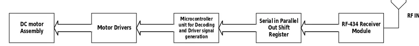
Figure 2 shows the block diagram of LABVIEW based Wireless Robot Toy Car Receiver section.
Motor Drivers
Serial in Parallel Out Shift Register
Microcontroller unit for Decoding and Driver signal generation RF-434 Receiver Module RF IN DC motor Assembly
Figure 2: Receiver section of LABVIEW based Wireless Robot Toy Car
It divides into five stages to receive and decode signals and drive the motor assembly.
ISSN (Print) : 2320 – 3765 ISSN (Online) : 2278 – 8875
I
nternational
J
ournal of
A
dvanced
R
esearch in
E
lectrical,
E
lectronics and
I
nstrumentation
E
ngineering
(An ISO 3297: 2007 Certified Organization)
Vol. 4, Issue 9, September 2015
2. Those Serialized signal is converted back to parallel data using Serial in parallel out shift register. 3. Those data is decoded using microcontroller unit.
4. Microcontroller sends signals to driver according to decoded data.
5. Motor drivers are used for isolation of high current devices from microcontroller and driving the motors by
providing high current output from low current input signal generated by microcontroller unit.
II. CIRCUIT DESCRIPTION
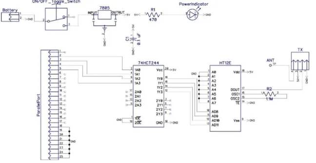
In this section we discuss about the transmitter and receiver circuits and program require to control the Toy car assembly. Figure 3 shows the schematic diagram of Transmission section of Robot Toy car.
Figure 3: Schematic Diagram of Transmitter Section
In the transmitter section 7805 fixed 5V regulator provides the 5V fixed supply from 9V battery to every component. Power indicator LED shows the status of Circuit i.e. turned ON or OFF. The data coming out from parallel port (description of Parallel port is available in Component section and LABVIEW in Software section) is feed to 74HCT244 a TTL/CMOS compatible Octal Buffer. This is done to convert the TTL logic level of Parallel port to CMOS level for HT12E. After the conversion the 4-bit parallel data is given to HT12E Data line D8-D11. HT12E converts the 8-address bits A0-A7 and 4-data bits D8-D11 to serial data and sends out from Dout Pin. The RF-434
Transmitter module Transmit the serialized data through 434 MHz RF channel using ASK modulation.
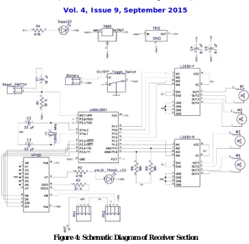
Figure 4 shows the schematic diagram of Receiver section of Robot Toy Car.
RF-434 Receiver module receive the serialized data sent out by the HT12E through Transmitter module and input it to
HT12D Din Pin. HT12D compares it’s Address of the A0-A7 address pins and received addresses, if both address match
then HT12D sends datato itsdata pin D8-D11 as well as send high signal on VT (valid transmission) pin. LED on VT pin glows when we send the data and blinked when data changes during operation.
ISSN (Print) : 2320 – 3765 ISSN (Online) : 2278 – 8875
I
nternational
J
ournal of
A
dvanced
R
esearch in
E
lectrical,
E
lectronics and
I
nstrumentation
E
ngineering
(An ISO 3297: 2007 Certified Organization)
Vol. 4, Issue 9, September 2015
Figure 4: Schematic Diagram of Receiver Section
III. MOTOR ASSEMBLY AND DRIVING MECHANISM
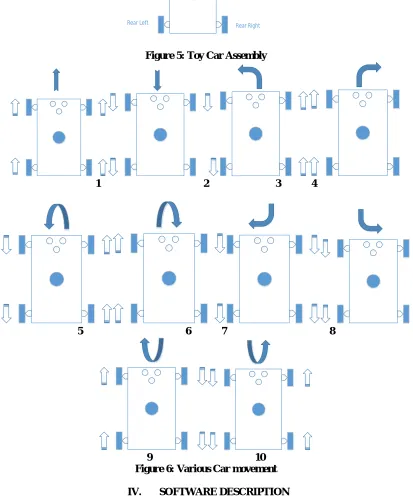
All four motors are connected in H-bridge configuration using L293D. To drive Car in various direction, we first need to understand the motion of various motors. The car assembly is shown in figure 5. Figure 6 shows direction of car along with direction of motor to move, forward arrow shows clockwise movement of motor while backward arrow anticlockwise. The top arrow shows the direction of car. The figure 6 divides into following Car movement
1. Forward movement (all motor clockwise movement, Figure 6.1)
2. Reverse Movement (all motor anticlockwise movement, Figure 6.2)
3. Sharp Left Forward (Right motors clockwise and Left motors are at hold, Figure 6.3)
4. Sharp Right Forward (Left motors clockwise and Right motors are at hold, Figure 6.4)
5. Drift Left Forward (Left motors anticlockwise and Right motors clockwise movement, Figure 6.5)
6. Drift Right Forward (Right motors anticlockwise and Left motors clockwise movement, Figure 6.6)
7. Sharp Left Reverse (Right motors anticlockwise and Left motors are at hold, Figure 6.7) 8. Sharp Right Reverse (Left motors anticlockwise and Right motors are at hold, Figure 6.8)
9. Drift Left Reverse (Left motors clockwise and Right motors anticlockwise movement, Figure 6.9)
ISSN (Print) : 2320 – 3765 ISSN (Online) : 2278 – 8875
I
nternational
J
ournal of
A
dvanced
R
esearch in
E
lectrical,
E
lectronics and
I
nstrumentation
E
ngineering
(An ISO 3297: 2007 Certified Organization)
Vol. 4, Issue 9, September 2015
Figure 5: Toy Car Assembly
1 2 3 4
5 6 7 8
9 10
Figure 6: Various Car movement
IV. SOFTWARE DESCRIPTION
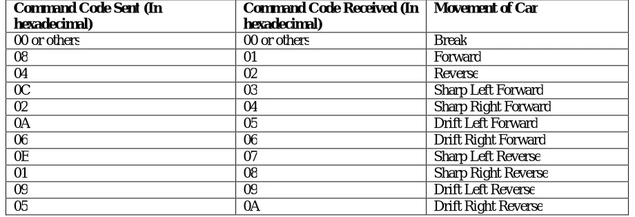
Before we start discussing about how LABVIEW sends data on parallel port and Control Sends command to various motors, we need to decide the which data does what? Let’s begin with the command send to controller wirelessly to move the car assembly in various way. Table 1 shows the Command signal for microcontroller which is
Front Left Front Right
ISSN (Print) : 2320 – 3765 ISSN (Online) : 2278 – 8875
I
nternational
J
ournal of
A
dvanced
R
esearch in
E
lectrical,
E
lectronics and
I
nstrumentation
E
ngineering
(An ISO 3297: 2007 Certified Organization)
Vol. 4, Issue 9, September 2015
send by LABVIEW software to command which direction car assembly moves. Table 2 shows the Data for Motor assembly how it moves.
Command Code Sent (In hexadecimal)
Command Code Received (In hexadecimal)
Movement of Car
00 or others 00 or others Break
08 01 Forward
04 02 Reverse
0C 03 Sharp Left Forward
02 04 Sharp Right Forward
0A 05 Drift Left Forward
06 06 Drift Right Forward
0E 07 Sharp Left Reverse
01 08 Sharp Right Reverse
09 09 Drift Left Reverse
05 0A Drift Right Reverse
Table 1: Command code for Toy Car
Motor 1 (Front Left) Motor 2 (Front Right) Motor 3 (Rear Left)
Motor 4 (Rear Right)
Data from P1 of microcontroller In Hexadecimal
Movement of Car
Red Black Red Black Red Black Red Black
1 0 1 0 1 0 1 0 AA Forward
0 1 0 1 0 1 0 1 55 Reverse
0 0 1 0 0 0 1 0 22 Sharp Left Forward
1 0 0 0 1 0 0 0 88 Sharp Right Forward
0 1 1 0 0 1 1 0 66 Drift Left Forward
1 0 0 1 1 0 0 1 99 Drift Right Forward
0 0 0 1 0 0 0 1 11 Sharp Left Reverse
0 1 0 0 0 1 0 0 44 Sharp Right Reverse
1 0 0 1 1 0 0 1 99 Drift Left Reverse
0 1 1 0 0 1 1 0 66 Drift Right Reverse
Table 2: Motor Command Signals for Microcontroller
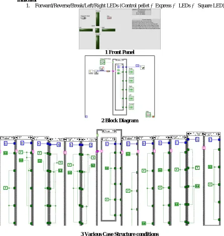
Figure 7 shows the VI that sends the command to microcontroller. This VI consist of following components: Functions
1. Initialized Keyboard (Function pellet Connectivity input device control):1
2. Acquire input data (Function pellet Connectivity input device control):1
3. Close input (Function pellet Connectivity input device control):1
4. Byte array to string (Function pellet Mathematics Numeric Conversion):1
5. Case Structure (Function pellet Programming Structure):2
6. While Loop (Function pellet Programming Structure):1
7. Outport.Vi (Function pellet Select Vi C:\program file\National instrument\Labview
ISSN (Print) : 2320 – 3765 ISSN (Online) : 2278 – 8875
I
nternational
J
ournal of
A
dvanced
R
esearch in
E
lectrical,
E
lectronics and
I
nstrumentation
E
ngineering
(An ISO 3297: 2007 Certified Organization)
Vol. 4, Issue 9, September 2015
Control
1. Sharp/Drift Mode Boolean button (Control pellet Express Button Push Button):1
2. Stop Boolean Button (Control pellet Express Button Text Button):1
Indicator
1. Forward/Reverse/Break/Left/Right LEDs (Control pellet Express LEDs Square LED):5
1 Front Panel
2 Block Diagram
3 Various Case Structure conditions Figure 7: LABVIEW VI
LABVIEW VI works as follows:
Initialized keyboard function initialize keyboard for Read/Write mode.
Acquire data input function waits for the keyboard key press and sends out the key press array.
ISSN (Print) : 2320 – 3765 ISSN (Online) : 2278 – 8875
I
nternational
J
ournal of
A
dvanced
R
esearch in
E
lectrical,
E
lectronics and
I
nstrumentation
E
ngineering
(An ISO 3297: 2007 Certified Organization)
Vol. 4, Issue 9, September 2015
o For up arrow key this function returns “f” , for down arrow key “;”, for left arrow key “D” and for
right arrow key “\”.
Boolean button Sharp/Drift modeselects the case for outer case structure and Scanned Key string selects case for inner case structure.
The code is send to Parallel port using outport.vi selected by Case structures.
This operation can be stopped by Pressing Stop button which stop the While loop.
Now let’s look at Microcontroller program for Toy car, it consist if else ladder of various commands sends by Transmitter module. As per the command received, Microcontroller sends out Command code to Motor assembly via Port 1 which is shown in table 2. This program is shown below.
//P3= rec_data, physical port //P1= motor_data, physical port #include <REG2051.H> #define rec_data P3 #define motor_data P1 sbit bit0=P3^2; sbit bit1=P3^3; sbit bit2=P3^4; sbit bit3=P3^5; void main(void){
motor_data=0x00; //make motor_cont as output rec_data=0xFF;
while(1) {
if(bit3==0 && bit2==0 && bit1==0 && bit0==0) //Break motor_data=0x00;
else if(bit3==0 && bit2==0 && bit1==0 && bit0==1) //Forward motor_data=0xAA;
else if(bit3==0 && bit2==0 && bit1==1 && bit0==0) //Reverse motor_data=0x55;
else if(bit3==0 && bit2==0 && bit1==1 && bit0==1) //sleft+fwd motor_data=0x22;
else if(bit3==0 && bit2==1 && bit1==0 && bit0==0) //sright+fwd motor_data=0x88;
else if(bit3==0 && bit2==1 && bit1==0 && bit0==1) //dleft+fwd motor_data=0x66;
else if(bit3==0 && bit2==1 && bit1==1 && bit0==0) //dright+fwd motor_data=0x99;
else if(bit3==0 && bit2==1 && bit1==1 && bit0==1) //sleft+rev motor_data=0x11;
else if(bit3==1 && bit2==0 && bit1==0 && bit0==0) //sright+rev motor_data=0x44;
else if(bit3==1 && bit2==0 && bit1==0 && bit0==1) //dleft+rev motor_data=0x99;
else if(bit3==1 && bit2==0 && bit1==1 && bit0==0) //dright+rev motor_data=0x66;
else
ISSN (Print) : 2320 – 3765 ISSN (Online) : 2278 – 8875
I
nternational
J
ournal of
A
dvanced
R
esearch in
E
lectrical,
E
lectronics and
I
nstrumentation
E
ngineering
(An ISO 3297: 2007 Certified Organization)
Vol. 4, Issue 9, September 2015
V. RESULT AND DISCUSSION
After constructing the Hardware and software, we can control the Robot toy car over 434 MHz RF channel using PC keyboard.
The tool we use here are:
Schematic and PCB is designed in Diptrace Free version for windows
LABVIEW 2013 32-bit edition is used with standard Parallel port available on Motherboard.
For this project Windows XP 32-bit is used.
Figure 1 shows the block diagram of transmitter section of the circuit which sends the command through the PC parallel port over RF Channel. Figure 2 shows the block diagram of Receiver section which receive the command over RF channel and generate signal to drive the motor assembly. Figure 3 shows the schematic of Transmitter section/Remote control circuit, similarly the figure 4 shows the schematic of Receiver section/motor assembly circuit designed in Diptrace. Figure 5 shows the 2D diagram of motor assembly while figure 6 shows various motion of motor assembly with direction. Figure 7 shows the VI of LABVIEW that controls and sends the various commands to motor assembly.
VI. CONCLUSION
After building this hardware and software one can control the Robot Toy car over RF 434 MHz frequency up to 4.19 Meters range. The control mechanism require PC keyboard Arrow keys while some controls are available as soft button in LABVIEW Front panel.
REFERENCES
1) Dr. Mahesh N. Jivani and Dr. Nikesh A. Shah, “Parallel-Port Interfacing and Programming AID”, EFY November 2007
2) Bodhibrata Mukhopadhyay and Gourabsil, Subhajit Mazumdar, “PC-Based Wireless Control for Toy Car”, Electronicsforyou.com article Section.