A Novel Design of Multiple Error Correction Codes with Fast
Decoding For a Subset of Critical Bits
A. Raghava Raju & Madala Naga Swapna
Associate Professor Dept. Of E.C.E
Chebrolu Engineering College Guntur DT
M.Tech – Scholar Dept. Of E.C.EChebrolu Engineering College Guntur DT
ABSTRACT : To protect data stored in memories and registers multiple error correction are widely used. A few control bits are added to the data in some applications such as networking, to facilitate their pressing. For example, flags to mark the start or the end of a packet are widely used. Therefore to protect both data and the associated control bits, it is important to have SEC Codes. The most attractive feature of these codes it to provide fast decoding of the control bits, as these are used to determine the processing of the data and are commonly on the critical timing path. A few additional control bits is presented to extend SEC codes. The derived codes support fast decoding of the additional control bits and are therefore suitable for networking applications.
INDEX TERMS: Error correction codes, high-speed networking memory, multiple error correction [SEC] .
I.INTRODUCTION
High speed processing of data is required by networking applications and thus rarely on complex integrated circuits. In routers and switches, packets typically enter the device through one port are processed and then sent to one or more output ports. Data is stored during this processing and moved through the device. To detect and correct errors the stored data must be protected and it is done by using error-correcting codes[ECCs]. To correct I-bit error single error correction codes are commonly used for memories and registers. One problem arises that is to facilitate its processing when protecting the data in network applications, so a few control bits are added to each data block. For example, flags to mark the start of a packet
[SOP] the end of a packet [EOP], or an error [ERR] are commonly used.
To determine the processing of the data these flags are used, and the associated control logic is commonly on the critical timing path. To access the control bits, if they are protected with an ECC, they must first be decoded. This decoding adds delay and may limit the overall frequency.
To protect the data and the control bits as different data blocks separate ECCS is used. For example, let us assume 128 bit data blocks with 3 control bits. Then a SEC code can protect a data block using 8 parity check bits, and another SEC code can protect the 3 control bits using 3 parity check bits. This method provides independent decoding of data and control bits which requires additional parity check bits reducing delay.
Fig. 1. Parity check matrix with 128 data bits.
Fig 1 represents parity check matrix for a minimum weight SEC codes that protects 128 data bits.
Fig. 2. Parity check matrix with 128 data and 3 control bits.
bits requires only 8 parity check bits, which saves 3 bits when compound to the use of separate ECCS fig 2 represents parity check matrix for a minimum weight SEC code that protects 128 data and 3 control bits. The decoding of the control bits in this case is more complex and incurs more delay.
II. DATA PROTECTION IN NETWORKING APPLICATIONS
Data rates that range from 10 to 100G bits are supported by modern networking equipment. In currrent ASIC’s the clock frequencies used are typically in the range of 300 MHZ to 1GHZ, and the clock frequencies in FPGA’S are typically lower. On chip packet data buses are used widely to support these high data rates, with typical widths between 64 and 2048 bits. In RAM’S frequently packet data is stored eg.1 in FIFO’S for adapting processing rates. It is necessary to delineate the packet boundaries when the packet data is stored. Each segment on the bus in the simplest case, can be delineated with a single Eop marker. The next valid segment is then assumed to be the start of the following packet. Designers also use SOP marker to explicitly mark the start of packets. In packet processing there are many cases where a packet is in error and it must be dropped. An additional control signal ( ERR) is required to mark such error packets.
Fig. 3 Typical packet data storage in a networking application.
As shown in fig3 it is attractive to store the data and the markers in a single wide memory. In this way, relatively fewer ECC bits are required. Typically in state machine which controls the reading of the subsequent data the makers are fed. For example, the state machine may need to read out a single packet, or it may need to read out a fixed number of bytes of data. ( e.g. deficit round robin scheduler). One of the most important to be known is to know the packet data size with a byte resolution. It is not sufficient to know the exact packet size with the simple SOP and EOP markers. Therefore it is necessary to store additional marker bits called EOPSIZE, which indicate how many of the bytes in the EOP transfer are valid.
III. PROPOSED METHOD
total weight and balanced row weights to minimize encoding and decoding delay.
To obtain a code that protects the additional control bits three additional data columns are added for example, the matrix is fig.3 can be used where three additional columns are added to the left.
Now, the problem is that, to decode the 3 control bits 8 parity check bits are computated and the results are compared against the column of the control bits. This is the most complex when compared with the decoding of an independent SEC for both date and control bits, our goal is to simplify the decoding of control bits. To simplify the decoding of control bits, the parity check bits can be divided in two groups, a first group is shared by both data and control bits and a second is used for the data bits. Then, the decoding of the control bits only requires the recomputation of the first group of parity check bits. This explained with an example, a 128-bit data block and 3 control bits protected with 8 parity check bits. These 8 bits are divided in a group of 3 and 5, 3 are shared between data and control bits and 5 is used only for the data bits. The first three parity check bits are used to protect the control bits and these are assigned different values for each control bit, and the remaining parity check bits are not used to protect control bits.
To protect the data bits the rest of the values are used, and for each value, different values of the remaining five parity check bits can be used. In this example, the first group has 3 bits which can take 8 values, of which 3 are used for the columns that correspond to the control bits. The remaining 5 values of the first group 3 bits are used to protect the data bits. As mentioned earlier, the second group of parity check bits has 5 bits that can be used to code 32 values for each
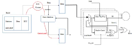
of the 5 values on the first group. Therefore,52 x32= 160 data bits of maximum can be protected. It is observed that the control bits can be decoded by simply recomputing the first three parity check bits. The decoding razor flipflop with typical packet data storage is shown in fig 4. The method is also used to protect more than three control bits. For example, to protect d data bits and C control bits using P parity check bits. Therefore P is divided into two groups Pcd and Pd. The first group is shared between control and data bits, and the second is used only for the data bits. To protect the data bits the number of combinations of the first group available is 2 pcd –c. For each of those, up to 2 pd values can be used, giving a total of ( 2 pcd-c) pd.
Fig. 4. Typical packet Bit decoding razor flipflop data storage in a networking application.
However the zero value , the combinations of the second group the with weight zero or one cannot be used, so that pd+1 should be subtracted. Similarly for the pcd value with the weight one on the first group, the zero value on the second group cannot be used as the resulting column would have weight one. Therefore, pcd should also be subtracted, giving a total of (2 pcd-c). 2pd -(p
d +1)- pcd . This is the number of data bits that can be protected in addition to the control bits. The razor flipflop is used for multiple bit error correction and verification the total operation.
control bits increases. The decoding of control bits is made more complex as pcd increases ,therefore the minimum value should be used. It is observed that, for the making of the decoding of the control bits more bits are needed in the first group.
However, still control bits can be decoded using only four syndrome bits instead of the eight bits required in a traditional SEC code.
EVALUATION: To assess the benefits, it has been implemented for 64, 128 and 256 data bits considering both 3 and 7 additional control bits. With minimum weight SEC codes the encodes and decodes are compared which balances the row weight proposed codes also have an impact on the decoding delay for the data bits. For the decoders, the added delay on data bits is significant for most word sizes. A circuit area is required by the proposed codes for both the encoder and the decoder similar to that of the minimum weight codes. In terms of delay, decoding of the data bits is slower on the other hand, the decoding delay is reduced by the proposed codes by approximately 9% - 11%. This reduction is smaller than that for the three control bits case. this is expected as the number of parity bit (pcd) used to decode the control bit increases and so does the decoder complexity.
IV. RESULTS
Fig. 5. OUTPUT WAVEFORM
IV. CONCLUSION
Here, a method to construct SEC codes which can protect a block of data and same additional control bits. The derived codes are designed to enable fast decoding of the control bits. The number of parity check bits are same for the derived codes and existing SEC codes and therefore do not require additional cost in term of memory or registers. To evaluate the benefits ,several codes are implemented and composed with minimum weight SEC codes. The proposed codes are useful in applications, where a few control bits are added to each each block and the control bits have to be decoded with two delay. Finally, the proposed one is extended to support more control bits by using one or more additional parity check bits. This would provide a solution to achieve fast decoding without using two separate codes for data and control bits.
V. REFERENCES
[1] P. Bosshart et al., “Forwarding metamorphosis: Fast programmable match-action processing in hardware for SDN,” in Proc. SIGCOMM, 2013, pp. 99–110.
[2] J. W. Lockwood et al., “NetFPGA—An open platform for gigabit-rate network switching and routing,” in Proc. IEEE Int. Conf. Microelectron. Syst. Educ., Jun. 2007, pp. 160–161.
[3] A. L. Silburt, A. Evans, I. Perryman, S.-J. Wen, and D. Alexandrescu, “Design for soft error resiliency in Internet core routers,” IEEE Trans. Nucl. Sci., vol. 56, no. 6, pp. 3551–3555, Dec. 2009. [4] E. Fujiwara, Code Design for Dependable Systems: Theory and Practical Application. Hoboken, NJ, USA:Wiley, 2006.
[5] C. L. Chen and M. Y. Hsiao, “Error-correcting codes for semiconductor memory applications: A state-of-the-art review,” IBM J. Res. Develop., vol. 28, no. 2, pp. 124–134, Mar. 1984.
A.RAGHAVA RAJU studied B.Tech at chirala engineering college and M.Tech at anna university, chennai. At present he is working as associate
professor at chebrolu
engineering college with 9 years of experience. His area of interest is V.L.S.I Design.
MADALA NAGA
SWAPNA studied B.Tech in
Malineni Lakshmaiah
women’s engineering college
and pursuing M.Tech at