Available online at www.ijrat.org
488
Power Quality Improvement In Distribution System Using Fuzzy
Based Iupqc Controller
1
Hothri Ravikindi,
2V.Venkata Sunil kumar,
3G. Anusha,
4SD.
Khajavali,
5G. Venkata Rohith
1Assistant Professor, Dept of EEE,Tirumala Engineering College, Narasaraopet, A.P, India
2,3,4,5B.Tech scholar, Dept of EEE, Tirumala Engineering College, Narasaraopet, A.P, India
Abstract:This paper proposes technique of FACTs based controller called as unified power quality conditioner, which is used to mitigate problems in power system and improving the transmission power based voltage and currents in the distribution systems. Reducing the rating of dc-link voltage without compromising the compensation technique is one of the advantage of unified power quality conditioner technique used in this paper. The series and shunt controllers as series connection with the combination of capacitor and inductor for filtering process, and the system neutral is also considered and directly connected to neutral of distribution system for avoiding the utilization of fourth leg in shunt converter voltage source inverter.
Key Words: Interline Unified Power Flow Controller, Power Quality, THD, PI Controller.
1. INTRODUCTION
In the advancement of power electronic devices, such as thyristors, GTO thyristors, Insulated Gate Bipolar Transistors and many more devices, which are used to control electric power [1].
In three phase systems, the power electronics devices could also cause unbalances in voltage and draw excessive neutral currents due to their disturbances. Due to because of these current harmonics and changes in reactive power, unbalances, and excessive neutral currents causes’ efficiency reduction and poor power factor. Therefore, improvement of power quality is one of the important issue since occurring of varying loads at distribution centers. Basically, the term Power Quality mainly deals with problems occurred in the system like improvement of voltage levels under variations in load or distribution levels at point of common coupling, maintaining of unity power factor from the supply, reducing the unbalances in current or voltages, harmonics in currents [2]. Conventionally, generally, passive filters has been used but
these filters have the disadvantages of fixed compensation, large size, ageing and resonance. By providing added flexibility, Flexible AC transmission system has the capability to maintain the line power at its thermal ratings. These facts can certainly overcome the any of stability limits.
2. OPERATING PRINCIPLE OF UNIFIED
POWER QUALITY CONDITIONER
Figure 1 shows The operational and control diagram IUPQC. Based on the other non-linear loads connected at PCC the voltage at PCC may be or may not be distorted. This diagram has two converters connected with the common dc link capacitor those are series and shunt [3]. Shunt APF i.e converter is connected shunt with the transmission line at load side for maintain the dc link voltage under constant levels for compensating the harmonic current. The other converters is a series converter which is connected in series with utility terminals through series injection transformers and it maintains the load voltage sinusoida l. Non linear load Other consumers Vinjected Distorted input voltage PCC Series inverter Shunt inverter
is iL
[image:1.612.144.460.522.732.2]igh
Available online at www.ijrat.org
As figure 2 shows the equivalent circuit for IUPQCsystem which consists of Voltage Source Converter. In this method, neutral terminal of the system and -Ve terminal of the dc bus along with the are grounded along with the series capacitor and inductor for shunt active filter. One of the
[image:2.612.114.527.145.373.2]passive capacitive element has the capability to supply a part of the reactive power based on the requirement of the load, and the active filter [4] will compensate the balance reactive power and the harmonics present in the load.
Figure 2: 3P4W IUPQC equivalent circuit The controlling technique for series and shunt
converter of IUPQC is designed based on the block diagram
shown in figure 3.
Figure 3: Block diagram of overall control structure with Series converter For achieving multi-level control objectives series
converters are used as mentioned in this last section. Hence, by considering suitable reference signals isα, isβ, isγ different techniques can be implemented by the block “function selection and combination” is shown in Figure 3 [4]. For negative-sequence voltage Compensation current reference is generated by the unbalance correction scheme. Desired currents for active/reactive power are obtained by the power
control strategy.
[image:2.612.133.521.405.644.2]Available online at www.ijrat.org
490 α-axis quantities are the actual load voltages and load
currents, whereas the lead/lag load voltages and 900 lag/lead load currents are implemented as β-axis quantities. 900 lead is
assumed in this paper for achieving a two-phase system for
each phase
.
Let us consider phase a with instantaneous values of load active and reactive powers as represented as
.
Where La = La + La , La = La + La
3. FUZZY LOGIC CONTROLLER
In the previous section, control strategy based on PI controller is discussed. But in case of PI controller, it has high settling time and has large steady state error. In order to rectify this problem, this paper proposes the application of a fuzzy controller . Generally, the FLC is one of the most important software based technique in adaptive methods.
As compared with previous controllers, the FLC has low settling time, low steady state errors. The operation of fuzzy controller can be explained in four steps.
1. Fuzzification 2. Membership function 3. Rule-base formation 4. Defuzzification.
In this paper, the membership function is considered as a type in triangular membership function and method for defuzzification is considered as centroid. The error which is obtained from the comparison of reference and actual values is given to fuzzy inference engine. The input variables such as error and error rate are expressed in terms of fuzzy set with the linguistic terms VN, N, Z, P, and Pin this type of mamdani fuzzy inference system the linguistic terms are expressed using triangular membership functions. In this paper, single input and single output fuzzy inference system is considered.
4. EXPERIMENTAL DIAGRAM AND RESULTS:
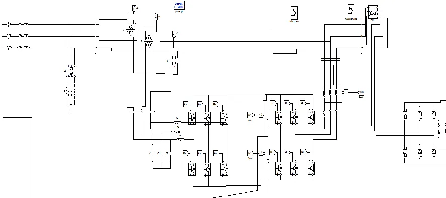
[image:3.612.82.525.479.676.2]The experimental setup is done in MATLAB/SIMULINK as per the circuit shown in figure 1. The simulation circuit for the proposed ANN based IUPQC system is shown in figure 4.
Available online at www.ijrat.org
[image:4.612.84.530.78.254.2] [image:4.612.83.532.293.439.2]Figure 5 Matlab/Simulink Waveforms for System Voltage and Current. Figure 5 shows the simulation results for the proposed system
voltages. The sag is created between 0.15 sec to 0.25 sec and during this time the input voltage is reduced to 20% of its final
value. And this drop is compensated with IUPQC system as shown in figure 5.
Figure 6 Matlab/Simulink Waveforms for System Voltage and Current with Fuzzy Controller. Figure 6 shows the system input, load and compensated
currents. Due to usage of non-linear loads the system load current is effected by distortions and these distortions can be
reduced by using shunt converter of IUPQC as shown in figure 6.
[image:4.612.138.476.485.684.2]Available online at www.ijrat.org
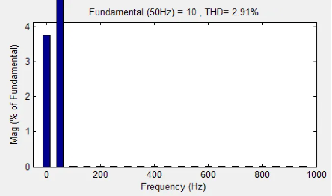
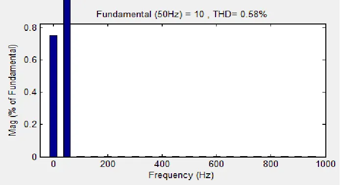
[image:5.612.133.482.82.271.2]492 Figure 8: THD for source voltage with Fuzzy controller
5. CONCLUSION
In this paper a 3P3W unified power quality conditioner is as a multi converter power conditioner which can be used for compensating for the various disturbance in voltage and for preventing the current harmonic.
The Proposed model of unified power quality conditioner has been observed by conducting experiment in Matlab/Simulink. From this simulation results we conclude that the harmonics caused by non-linear loads in voltage and currents can be reduced. A suitable mathematical model of the IUPQC developed for designing of series and shunt converter controllers. Simulation results satisfies the compensation technique at both cases and the implemented results with PI controllers and the results are compared between these two controllers.
REFERENCES
[1] Chen G, Chen Y and Smeldy K M, “Three-phase
four-leg active power quality conditioner without references calculation“ in
Proc.19th IEEE APEC, 2004, (1), pp.829-836. [2] Quinn C A and Mohan N. “Active filtering of
harmonic currents in three-phase, four-wire systems with three-phase and single-phase nonlinear loads” in proc. 7th IEEE APEC, 1992. Pp. 829-836.
[3] Akagi H, Kanazawa Y and Nabae A, “Instantaneous reactive power compensators comprising switching devices without energy storage components.” IEEE Transactions Industrial Applications, 1984 May/Jun, 1A-20(3). Pp. 625-630.
[4] K. A. Rani Fathima and T. A. Raghavendiran “A Novel Intelligent Unified Controller for the Management of the Unified Power Flow Controller (UPFC) using a Single Back Propagation Feed Forward Artificial Neural Network”, Indian Journal of Science and Technology, Vol 7(8), 1155–1169, August 2014.
[5] Gowrishankar Kasilingam and Jagadeesh Pasupuleti “Coordination of PSS and PID Controller for Power
System Stability Enhancement – Overview” Indian Journal of Science and Technology, Vol 8(2), 142– 151, January 2015.
[6] Correa I M, Chakraborty S, Simoes M G, and Farrent F A, “A single phase high frequency AC microgrid with an unified power quality conditioner” in Conf. Rec. 38th IEEE Ias Annu. Meeting, 2003, vol. 2, pp. 956-962.
[7] Alireza Rezvani, Maziar Izadbakhsh, Majid Gandomkar and Saeed Vafaei “Investigation of ANN-GA and Modified Perturb and Observe MPPT Techniques for Photovoltaic System in the Grid Connected Mode”, Indian Journal of Science and Technology, Vol 8(1), 87–95, January 2015. [8] Aredes M, Heumann K, and Watanabe M H, “An
universal active power line conditioner”, IEEE Transactions Power Delivery, 2009 Apr 13(2), pp. 545-551.