International Journal of Research in Advent Technology, Vol.2, No.5, May 2014
E-ISSN: 2321-9637
1
Implementation of Multidirectional Parity Check Code
Using Hamming Code for Error Detection and
Correction
Vishal Badole
1, Amit Udawat
2Department of Electronics and Communication Engg. 1, Acropolis Technical Campus, Indore 1
Department of Electronics and Communication Engg.2, Acropolis Technical Campus, Indore 2
Email: [email protected]1, [email protected]2
Abstract- Reliability and efficiency for data transmission play important role in data computer network. As
communication system is nondeterministic in its nature so reliability of data transmission deals with probability of error. Generally two techniques forward error correction (FEC) and channel coding are employed to control the error in communication system during data transmission. The proposed technique is a channel coding technique which improves efficiency as well as reliability of data transmission. In this technique Multidirectional parity code along with Hamming code are employed on communication system to detect and correct the error in data as well as check bits or redundant bits generated from the data. In the proposed error detection and correction technique Multidirectional parity code is used for detection and correction of error in data part and Hamming code is employed for detection and correction of error in multidirectional parity check bits or redundant bits in received codeword. The technique can correct four bit error, three bit error from data part using Multidirectional parity code and one bit error from redundant bits, in received code vector. Encoder and decoder for proposed technique has been realized using MATLAB.
Index Terms- Error Detection, Error Correction, Bit Overhead (BO), Code Rate (R), Reliability of data
transmission .
1. INTRODUCTION
As the demand of data transmission increased, reliability and efficiency of data transmission system becomes more advisable. The reliability and efficiency of data transmission can be improved by making use of channel coding and source coding techniques respectively. Source coding deals with transformation of data from one form to another whereas in channel coding the data is made secured from the noise by making use of error detection and correction techniques (EDAC). Up to now a number of EDAC methods are proposed to protect the data from noise but the reliability of data transmission is still a big challenge in noisy environment.
This paper presents a reliable and high efficient technique for detection and correction of
error. The proposed EDAC is based on
Multidirectional parity code with Hamming code. In this technique Multidirectional parity code secure the data part and Hamming code provide security to redundant bits against burst error in noisy environment. In this technique Multidirectional parity code with Hamming code can correct four bit of error, three error bit from data and one error from redundant bits that characterize data.
2. LITERATURE REVIEW
N. Babu Anne et al. [1] proposed a four dimensional parity check technique which can correct
3. PROPOSED METHODOLOGY
The proposed technique is a combination of existing Multidirectional parity code and H
code. At transmitter end, the information which is to be transmitted is converted in binary data and in a memory of size ( = No. of rows and No. of columns). On this binary data
memory section, Multidirectional parity code is applied. Application of Multidirectional parity code on binary data generates parity bits also known as multidirectional parity check bits in horizontal, vertical and directions. These multidirectional parity check bits are further encoded using Hamming code. For generating a systematic codeword
are appended at the end of data. Now t
codeword which contain data as well as redundant bits is transmitted through media. At receiver end, the received codeword is decoded using Multidirectional parity code and Hamming code decoder to detect and correct error in data and multidirectional parity check bits which characterize data. The general model for communication system using multidirectional parity code and Hamming code is shown in
Figure 3.1 Communication system using
multidirectional parity code and Hamming code
3.1 Encoding of data
At transmitter end, for encoding of information it is converted into binary data and in a memory of size . After it
parity code is applied on this binary data
against noise. Application of Multidirectional parity code generates horizontal, vertical and diagonal parity check bits using modulo-2 addition. These encoded check bits are known as redundant bits
code vector these encoded parity check appended at the end of data.
Consider 9 bit binary data is stored in a memory section of size 3 3 and multidirectional
3. PROPOSED METHODOLOGY
The proposed technique is a combination of Multidirectional parity code and Hamming information which is to is converted in binary data and stored = No. of rows and = . On this binary data, stored in a nal parity code is directional parity code on binary data generates parity bits also known as multidirectional parity check bits in horizontal, vertical and directions. These multidirectional parity further encoded using Hamming code. ic codeword these check bits Now this systematic which contain data as well as redundant bits transmitted through media. At receiver end, the received codeword is decoded using Multidirectional amming code decoder to detect and multidirectional parity check The general model for using multidirectional parity code and Hamming code is shown in Figure 3.1 [8].
.1 Communication system using
code and Hamming code
At transmitter end, for encoding of it is converted into binary data and stored After it Multidirectional binary data to protect it against noise. Application of Multidirectional parity horizontal, vertical and diagonal parity 2 addition. These encoded dant bits. To form a encoded parity check bits are
bit binary data is stored in a and multidirectional
parity code is applied on it. In multidirectional parity code implementation , and
of errors in the horizontal, vertical and diagonal of data part respectively, given as
, , and
where , , , , , and
represent positions of error in horizontal, vertical and diagonal directions respectively
multidirectional parity check bits in horizontal, vertical and diagonal directions
[8].
Figure 3.2 Multidirectional parity check bi generation
The expression of calculating horizontal, vertical and diagonal parity check bits
Calculation of horizontal parity check bits
⨁
⨁
⨁
⨁
⨁
⨁
Calculation of vertical parity check bits
⨁
⨁
⨁
⨁
⨁
⨁
Calculation of diagonal parity check bits
⨁
⨁
⨁
⨁
These calculated multidirectional parity check bits are encoded using Hamming code before transmission.2 parity code is applied on it. In multidirectional parity represent the number of errors in the horizontal, vertical and diagonal of
data part respectively, given as , , ,
, , , ,
and , , , ,
positions of error in horizontal, vertical and diagonal directions respectively [8]. Generation of multidirectional parity check bits in horizontal, s is shown in Figure 3.2
Multidirectional parity check bits generation
The expression of calculating horizontal, vertical and diagonal parity check bits are given as
Calculation of horizontal parity check bits
(3.1) (3.2)
(3.3) Calculation of vertical parity check bits
(3.4) (3.5) (3.6) Calculation of diagonal parity check bits
(3.7) (3.8)
(3.9) (3.10)
(3.11) These calculated multidirectional parity check bits are
International Journal of Research in Advent Technology, Vol.2, No.5, May 2014
E-ISSN: 2321-9637
3 After the calculation of multidirectional
parity check bits Hamming code is applied on these redundant bits for detection and correction of error in them and transmitted with the data.
Consider , ℎ , ℎ , , , and
, , , , are multidirectional parity check bits
and , , and are Hamming check bits in
[image:3.595.310.536.448.668.2]Hamming code [8]. On applying Hamming code on multidirectional parity check bits the Hamming parity check bits are generated by setting even parity over each Hamming check bit and its associated multidirectional parity check bits using modulo-2 addition. Figure 3.3 shows the positions of Hamming check bits along with multidirectional parity check bits in the Hamming code vector or check bit vector.
Figure 3.3 Hamming code vector/ Check bit vector Expression of calculating Hamming check bits from multidirectional parity check bits are given as
=
⨁
⨁
⨁
⨁
⨁ℎ ⨁ℎ
(3.12)=
⨁
⨁
⨁
⨁
⨁
⨁ℎ ⨁ℎ
(3.13)
=
⨁
⨁
⨁
⨁ℎ ⨁ℎ ⨁ℎ
(3.14)=
⨁
⨁
⨁
⨁ℎ ⨁ℎ ⨁ℎ
(3.15) [image:3.595.75.295.534.764.2]Hamming check bits shown by (3.12) to (3.15) along with multidirectional parity check bits given by (3.1) to (3.11) are known as redundant bits and sent with data as check bit vector. Generation of check bit or redundant bit vector using Hamming encoder is shown in Figure 5.5.
Figure 3.4 Hamming encoder
3.2 Decoding of data
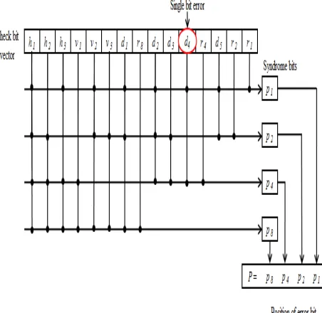
At receiver end, Hamming decoder is used to decode the redundant bits and to detect and correct single bit error from multidirectional parity check bits. When the transmitted code vector is received, a parity bit is calculated over each group of bits (Multidirectional parity check bit and Hamming parity check bit) and stored in a syndrome value from right to left. Parity for check bit 1 and its associated bits are rightmost in the syndrome value, parity for check bit 2 and its associated bits are to the left, then parity for check bit 4, and so forth. If the syndrome value is 0, there is no error in multidirectional parity check bits. For single bit error, the syndrome value identifies the erroneous bit, which needs to be inverted.
Consider
,
,
and are syndromebits in a syndrome . Calculation of syndrome bits are given as
=
⨁
⨁
⨁
⨁
⨁ℎ ⨁ℎ ⨁
(3.16)
=
⨁
⨁
⨁
⨁
⨁
⨁ℎ ⨁ℎ ⨁
(3.17)
=
⨁
⨁
⨁
⨁ℎ ⨁ℎ ⨁ℎ ⨁
(3.18)
=
⨁
⨁
⨁
⨁ℎ ⨁ℎ ⨁ℎ ⨁
(3.19) Decoding of redundant bits in received code vector is
shown in Figure 3.5
Figure 3.5 Hamming decoder
4 are regenerated from the received data and bit
positions of these parity bits are compared with the received one. If comparison does not reflect any difference between received and recalculated parity bit position and = 0, = 0 and = 0, it shows that the received data at the receiver end is not affected by noise and if the comparison reflects difference between the received and recalculated parity bit position and ≠ 0 or ≠ 0 or ≠ 0, the erroneous parity lines are identified and then the correction process starts [1, 2].
[image:4.595.266.519.79.693.2]The position of error bit in received data is detected by determining the intersection point of corrupted parity bits. The Intersection point of all corrupted parity bits indicate the position of error bit in data and this corrupted bit is changed from 0 to 1 or 1 to 0 to get the correct data bit.. Detection of a single bit error is shown in Figure 3.4 [8] in which dashed circles show corrupted bit position in horizontal, vertical and diagonal directions and continuous circles show the error bit position in data part of received codeword.
Figure 3.6 Regeneration of multidirectional parity bits for error detection and correction
5. RESULTS
The proposed technique is implemented
using MATLAB. The results obtained after
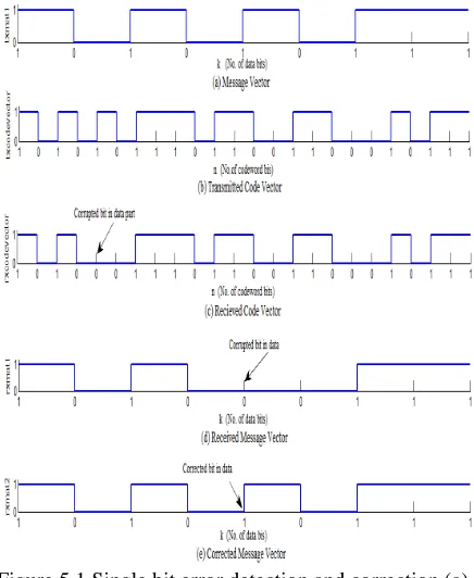
[image:4.595.307.525.89.355.2]implementation of this technique for burst error detection and correction are shown by Figure 5.1 to 5.4.
Figure 5.1 Single bit error detection and correction (a) Message vector (b) Transmitted code vector (c) Received code vector (d) Received message vector (e)
Corrected message vector
Figure 5.2 Double bit error detection and correction (a) Message vector (b) Transmitted code vector (c) Received code vector (d) Received message vector (e)
[image:4.595.78.291.353.615.2]International Journal of Research in Advent Technology, Vol.2, No.5, May 2014
E-ISSN: 2321-9637
[image:5.595.72.569.82.751.2]5 Figure 5.3 Triple bit error detection and correction
(a) Message vector (b) Transmitted code vector (c) Received codevector (d) Received message vector
(e) Corrected message vector
Figure 5.4 Four bit error detection and correction (a) Message vector (b) Transmitted code vector (c) Received code vector (d) Received message vector
(e) Corrected message vector
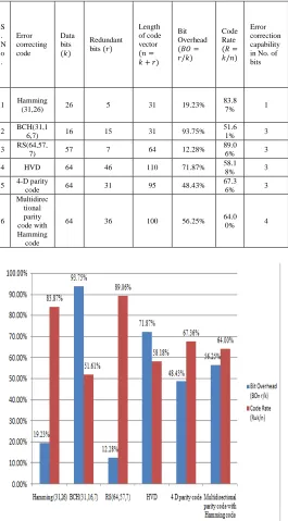
On the basis of Code Rate and Bit Overhead the proposed scheme is compared with other EDAC codes as shown in Table 5.1. It is clear that Hamming code has minimum Bit Overhead and maximum Code Rate but the error correction capability is 1 bit. BCH code and Reed Solomon both can correct up to three bit error in received codeword but in the case of both methods decoding algorithm is too complex. The
[image:5.595.306.571.267.746.2]HVD code can also correct up to 3 bit error with high efficiency but bit overhead is maximum and Code Rate is minimum as compared to 4-D parity code. But in case of all EDAC codes if redundant bits are also corrupted during transmission they are not capable to detect and correct the error in redundant bits. The proposed technique can correct four bit error, three error bits from the data parts and one error bit from redundant bits, in received codeword with acceptable Code Rate and Bit Overhead. Performance of proposed technique over other burst error correcting code is given in Figure 5.5.
Table 5.1 Comparison between different EDAC codes
Figure 5.5 Performance of different EDAC codes
S . N o .
Error correcting code
Data bits
( )
Redundant bits ( )
Length of code vector
( = + )
Bit Overhead
("# = / )
Code Rate
(% = / )
Error correction capability in No. of bits
1 Hamming
(31,26) 26 5 31 19.23% 83.8
7% 1
2 BCH(31,1
6,7) 16 15 31 93.75% 51.6
1% 3 3 RS(64,57,
7) 57 7 64 12.28% 89.0
6% 3 4 HVD 64 46 110 71.87% 58.1
8% 3 5 4-D parity
code 64 31 95 48.43% 67.3
6% 3
6
Multidirec tional parity code with Hamming code
[image:5.595.73.297.390.617.2]6
6. CONCLUSION
This paper presents a technique which comprises Multidirectional parity code with Hamming code for detection and correction of burst error with improvement in reliability and efficiency of data transmission. As this technique is compared with other EDAC and it is found that the error correction capability of proposed technique is four error bit and architecture for encoder and decoder are less complex than other EDAC. The proposed scheme can be used efficiently where retransmission of data is complicated and so costly and check bits in codeword are also corrupted by noise. This technique can correct three bit error from data as well as one bit error in check bits. The Bit Overhead and Code Rate for this technique are 56.25% and 64% respectively which provide better results for error detection and correction than other techniques.
REFERENCES
[1]
N. Babu Anne, U. Thirunavukkarasu, Dr. S. Latifi, , (2004),“Three and Four-dimensional Parity-check Codes for Correction and Detection of Multiple Errors”, International Conference onInformation Technology: Coding and Computing,
Volume 2, pp. 837-842.
[2] V. Gupta, Dr. C. Verma, (2012), “Error Detection and Correction: An Introduction”, International
Journal of Advanced Research in Computer Science and Software Engineering”, Volume 2,
Issue 11, pp. 212-218.
[3] M. Kishani, H. R. Zarandi, H. Pedram, A. Tajary, M. Raji, B. Ghavami, , (2011), “HVD: horizontal-vertical-diagonal error detecting and correcting code to protect against with soft errors", Design Automation for Embedded
Systems, Volume 15, Issue 3-4, pp. 289-310.
[4] M. Imran , Z. Al-Ars, G. N. Gaydadjiev, (2009), “Improving Soft Error Correction Capability of 4-D Parity Codes”, 14th IEEE European Test
Symposium(ETS 2009), t.b.s.
[5] P. Sharma, K. Kumar, A. K. Singh, , (2012), “Single bit error detection and correction by matrix method”, International Journal of Research & Innovation in Computer Engineering,
Volume 2, Issue 2, pp. 201-206.
[6] S. Sharma, Vijaykumar P.,” An HVD Based error detection and correction of soft errors in
semiconductor memories used for space
application”, International conference on devices,
circuits and systems (ICDCS), pp. 563-56.
[7] M. Jabeen, S. Khan, (2012), “Design of Convolution Encoder and Reconfigurable Viterbi Decoder”, International Journal of Engineering
and Science, Volume 1, Issue 3, pp. 15-21.
[8] V. Badole, A. Udawat, (2014), “Design of Multidirectional Parity Code using Hamming Code Technique for Error detection and
correction”, PARIPEX- Indian Journal of