Hardware Manual
28i/124i/384i
Hardware Manual
28i/124i
1-1
In this section
. . . .
Page
Installing the Cabinets . . . .1-3
Unpacking . . . 1-3 Before Installing . . . 1-3 Site Requirements. . . 1-3 Removing the 28i Covers . . . 1-4 Mounting the 28i Cabinets . . . 1-4 Removing the 124i Covers . . . 1-5 Mounting the 124i Cabinets . . . 1-5
Connecting Expansion Cabinets . . . .1-8
Installing EXIFU PCBs . . . 1-8
Grounding the Cabinets . . . .1-10
Connecting the Ground Wires - 28i System . 1-10 Connecting the Ground Wires - 124i System. 1-11
Section 1, INSTALLING THE MAIN AND EXPANSION CABINETS
1. Installing Cabinets
1-3
Unpacking
Unpack the equipment and check it against your equipment lists. Inspect for physical damage. If you are not sure about a compo-nent’s function, review the Product Description Manual. Contact your Sales Representative if you have additional questions.
Have the appropriate tools for the job on hand, including: a test set, a punch down tool and a digital voltmeter.
Before Installing
Make sure you have a building plan showing the location of the common equipment, extensions, the telco demarcation and earth ground. In addition, the installation site must meet the requirements outlined in the Standard Practices Manual.
Site Requirements
The common equipment is contained in three wall-mounted cab-inets: the Main Cabinet and two Expansion Cabinets. Choose a central location for the cabinets that allows enough space for the equipment — and provides enough room for you to comfortably work. The Installation Layout (Figure 1-4 and Figure 1-5 on pages 1-6 and 1-7) shows you about how much space your sys-tem requires.
Each common equipment cabinet requires a three-prong dedi-cated 110 VAC 60 Hz circuit (NEMA 5-15 receptacle) lodedi-cated within 7 feet of the AC receptacle. You should install the exten-sion and trunk blocks to the right of the Main Cabinet. Telco should also install the RJ21X to the right of the Main Cabinet.
1. Installing Cabinets
1-4
Removing the 28i Cover (Figure 1-1)
To make installation easier, remove the cover on the KSU. 1. Unscrew the two captive screws on the front of the cabinet
cover.
2. Lift up slightly on the front of the cover – then gently slide the cover back to remove it.
Figure 1-1 REMOVING THE 28i COVER
Mounting the 28i Cabinet (Figure 1-2)
1. Using the screws provided, attach the metal bracket to the Main Distribution Frame (MDF) plywood backboard. Mount the bracket in a convenient location, about 12” higher than where you want the bottom of the cabinet to line up. 2. Hang the KSU on the metal bracket.
3. Install two mounting screws (provided) in the lower left and right hand corners of the KSU to secure it to the plywood backboard.
The right side panel of the KSU can also be taken off by removing the screws at the top and bottom of the side panel.
Figure 1-2 HANGING THE 28i CABINET
80000 - 13
80000 - 12
INSTALLING THE 28i CABINET
1. Installing Cabinets
1-5
Removing the 124i Covers (Figure 1-3)
To make wall-mounting easier, remove the cover on each com-mon equipment cabinet. This allows you to use the cabinets as a mounting template.
1. Unscrew the two captive screws on the right side of the cabi-net cover.
2. Lift up the right side of the cover — then slide the cover to the left to remove it.
Figure 1-3 REMOVING THE 124i COVER
Mounting the 124i Cabinets (Figure 1-4 and Figure
1-5)
1. Using suitable fasteners, mount a Main Distribution Frame (MDF) plywood backboard in a centrally located spot.
2. Hold the Main Cabinet against the MDF and mark all four mounting holes.
3. Drill the marked holes using a 1/8” drill bit.
4. Install two mounting screws (provided) in the top two holes, leaving about 3/8” shank exposed.
5. Hang the Main Cabinet on the top two screws and fasten in place.
6. Install the bottom two screws and tighten in place.
7. Following the procedure above, install the expansion cabi-nets (if required).
92001
2
9
1. Installing Cabinets
1-6
Figure 1-4 28i INSTALLATION LAYOUT
Continued on next page. . .
80000 - 15
Plywood backboard
Dedicated AC Outlet Surge
Protector
To earth ground To telco
ground
Station Blocks
Station Blocks Trunk
Blocks 4'
4'
INSTALLING THE CABINETS
1. Installing Cabinets
1-7
INSTALLING THE CABINETS
Figure 1-5 INSTALLATION LAYOUT
To Verified Earth Ground Note: Each cabinet is shown in a typical 8 x 24 configuration.
Dedicated AC Outlet Dedicated AC Outlet Dedicated AC Outlet
Surge
Protector Surge Protector Surge Protector
Plywood Backboard
To Telco To Telco
To Telco
To Stations To Stations
To Stations
Trunk Blocks
Trunk Blocks
Trunk Blocks
Station Blocks
Station Blocks
Station Blocks
4’
4’
Expansion Cabinet #1
Main Cabinet
1. Installing Cabinets
1-8
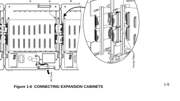
Installing EXIFU PCBs on the 124i (Figure 1-6)
Each 124i expansion cabinet requires an EXIFU Expansion Interface PCB.
To connect Expansion Cabinet #1 to the Main Cabinet:
1. In Expansion Cabinet #1, plug the EXIFU PCB into the first (CPRU) slot.
2. Plug the EXIFU PCB ribbon cables into the two connectors at the top of the Main Cabinet backplane.
3. Install the ferrite filters as shown.
4. Install the metal strain reliefs in both the Main and Expansion #1 cabinets.
To connect Expansion Cabinet #1 to Expansion Cabinet #2:
1. In Expansion Cabinet #2, plug the EXIFU PCB into the first (CPRU) slot.
2. Plug the EXIFU PCB ribbon cables into the two connectors at the top of Expansion Cabinet #1.
3. Install the metal strain reliefs in both expansion cabinets.
1. Installing Cabinets
1-9
CONNECTING EXPANSION CABINETS
92001 - 3 0a
AC Cord AC Cord
Expansion CEU #2 Expansion CEU #1 Main CEU
Ferrite Filters
EXIFU-S1 PCB
EXIFU-S1 PCB
1. Installing Cabinets
1-10
Connecting the Ground Wires on the 28i System
(Figure 1-7)
The 28i cabinet has two ground connections: ETH (Earth Ground) and PBXG (PBX Ground).
1. Using 12 AWG stranded copper wire, wind three turns of the ground wire around the core.
2. Loosen the lugs on both ground connections.
3. Using 12 AWG stranded copper wire, run a short jumper between the ETH and PBXG lugs.
4. Using the piece of 12 AWG stranded copper wire that is wrapped around the core, connect the PBXG connection to a known earth ground.
5. Firmly tighten both the ETH and PBXG connections.
6. Using the plastic strap located at the base of the cabinet, secure the core to the cabinet.
DO NOT PLUG IN THE CABINET POWER CORD WITHOUT FIRST INSTALLING THE PCBS.
Figure 1-7 GROUNDING A CABINET
92700 - 04
To earth ground To telco ground
1. Installing Cabinets
1-11
Connecting the Ground Wires on the 124i
System (Figure 1-8)
Each 124i cabinet has two ground connections: ETH (Earth Ground) and PBXG (PBX Ground).
1. Loosen the lugs on both ground connections.
2. Using 12 AWG stranded copper wire, run a short jumper between the ETH and PBXG lugs.
3. Using another piece of 12 AWG stranded copper wire, con-nect the PBXG concon-nection to a known earth ground.
4. Firmly tighten both the ETH and PBXG connections.
DO NOT PLUG IN THE CABINET POWER CORDS WITH-OUT FIRST INSTALLING THE PCBS.
ONCE ALL THE PCB’S HAVE BEEN INSTALLED AND THE CONNECTIONS MADE, YOU MUST REPLACE THE KSU’S COVER IN ORDER TO KEEP THE PCB’S IN PLACE AND TO PREVENT INTERMITTENT RESETS FROM A LOOSE PCB.
Figure 1-8 GROUNDING A CABINET
Now that your cabinets are installed and grounded, go to Part
2: PCB Installation and Startup.
To Verified Earth Ground
926 - 4 3
ETH Jumper
PBXG
GROUNDING THE CABINETS
2-1
Section 2, PCB INSTALLATION AND STARTUP
Caution
Do not plug in PCBs with the power applied.
Always unplug the cabinet’s AC power cord before inserting or removing PCBs.
In this section . . . .Page
Installing PCBs (cont.)
BRI (BRIU) Interface PCB . . . 2-20 Analog Station (ASTU) PCB . . . 2-22 Analog Trunk (ATRU) PCB . . . 2-24 Caller ID (4CIDU) Daughter Board . . . 2-25 Ground Start (4GSAU) Daughter Board . . . . 2-26 E&M Tie Line (2EMTU) PCB . . . 2-28 DID (2DIDU) PCB . . . 2-29 Page/Door Box (PGDU) PCB . . . 2-30 Tone Detector (DTDU) PCB. . . 2-32 28i System: Power-Up Sequence . . . 2-33 124i System: Power-Up Sequence . . . 2-34 Upgrading the Advanced Feature (EXCPRU)
Module Software Version for the 124i . . . 2-35
In this section . . . .Page
28i Hardware Information . . . .2-2
System Load Factors . . . 2-2
PCB Location . . . .2-3
Where to Install the PCBs in a 28i System . . . 2-3 Where to Install the PCBs in a 124i System . . 2-4
Installing PCBs . . . .2-4
28i Hardware Information
2. PCB Installation and Startup
2-2 The 28i system uses software comparable to the 124i base
sys-tem. This means that any features that are available in the 124i base system are available in the 28i system as long as the soft-ware level is the same. Check with your sales representative for the availability of DID and BRI trunks.
System Load Factors
When connecting equipment to the 28i system, always consider the Load Factor Table. This table shows the relative power requirements for each device that you can connect. The following PCB’s have no load factor: 24CPRU, 4CIDU, 4DTDU, 4PGDU, 4ATRU, 8DSTU, and LAPB. In order not to exceed the load
factor, the system should not exceed a maximum of two station PCBs (either 8DSTU or 4ASTU).
To use the Load Factor Table:
1. Multiply the number of devices (column 4) by their load factor (column 3).
For example, 16 key telephones plus 1 ASTU have a load factor of 23.
2. Enter the result from step 1 in column 5 (Total Device Load).
3. Add up all the entries in column 5. Total cabinet load
can-not exceed 23.
Load Factor Table
Total
Connected Part Load Number Device
Device Number Factor Installed Load
All Key Telephones ---- 1
DSS Console 92555 TBD
Door Box 88540 TBD
2DIDU PCB 92016 8
4ASTU PCB 92040 7
(includes 4 SLT’s)
VAU Module (3 port) 92136 2 VAU Module and 92136 +
Expansion (6 port) 92137 2.5
2-OPX Module 92177 4
ACI Module 92259 .5
DCI-A/B 92266 or
92267 .5
3-DCI Module 92258 2
2-3
PCB LOCATION
Where to Install the PCBs in a 28i System (Figure 2-1)
Maximum 16 Trunks
Configuration: 20 Extensions (16 digital/8 analog)
(All configurations are not available at the same time.)
The system’s universal architecture gives you flexibility when installing PCBs. You can install a PCB in any slot, provided you follow the guidelines in the chart below and keep within the limits of the load factor. The number of extensions must be limited to 20 due to the load factor for the system.
Item Description Location Max.
24CPRU Central Processing Unit CPRU in Slot 1 1
8DSTU 8 Digital Stations Slot 2 1
4ASTU 4 Analog Stations Slots 2-5 2 * *Due to Load Factors, the 4ASTU PCB maximum is limited to 2.
4ATRU 4 Analog Trunks Slots 2-5 4
2DIDU 2 DID Trunks Slots 2-5 4
2BRIU 2 BRI Circuits Slots 2-5 4
4PGDU 4 Page/Door Box Slots 2-5 2
4DTDU Dial Tone Detection Slots 2-5 2 LAPBU LAPBU Unit Installs on CPRU PCB 1 4CIDU Caller ID Installs on 4ATRU PCB 4 4GSAU Ground Start Installs on 4ATRU PCB 4
Figure 2-1 PCB LOCATION
1
2 3 4 5
4 PDGU (Page/Door Box) or
4 DTDU (Dial Tone Det.) or
2 DIDU (DID) 4 ASTU (Analog Station)
or
4 ATRU (Analog Trunk) or
CPRU with optional LAPB PCB
or
8 DSTU (Digital Station)
4 ATRU (Analog Trunk)
4 PDGU (Page/Door Box)
4 DTDU (Dial Tone Det.)
2 DIDU (DID) or
4 ASTU (Analog Station)
92700 - 01
or
or or or 2 BRIU (BRI Trunk)
PCB LOCATION
2. PCB Installation and Startup
2-4
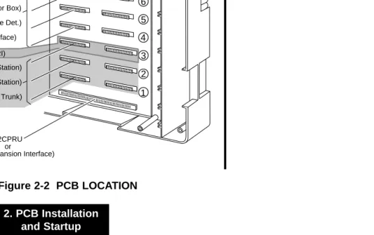
Where to Install the PCBs in a 124i System
(Figure 2-2)
Maximum Configuration: 52 Trunks
72 Extensions
The system’s universal architecture gives you great flexibility when installing PCBs. You can install a PCB in any slot, provid-ed you follow the guidelines in Figure 2-2 and the chart below.
Item Description Location Max.
32CPRU Central Processing CPRU slot in Main 1 Unit
8DSTU 8 Digital Stations Slots 1-3 in any 3 per cabinet cabinet 9 per system PRIU 24 T1/PRI Trunks/ Slot 3 in any cabinet 1 per cabinet
Channels 2 per system
BRIU 2 Two-Channel Slots 4-8 in any 5 per cabinet BRI Circuits cabinet 13 per system 4ASTU 4 Analog Stations Slots 1-8 in any 8 per cabinet
cabinet 15 (with DSTU) per system 16 (without DSTU)
per system
4ATRU 4 Analog Trunks Slots 1-8 in any 8 per cabinet cabinet 13 per system 2EMTU 2 Tie Line Trunks Slots 4-8 in any 5 per cabinet
cabinet 13 per system 4PGDU 4 Page/Door Box Slots 4-8 in any 2 per system
cabinet
4DTDU Dial Tone Detection Slots 4-8 in any 2 per system cabinet
2DIDU 2 DID Trunks Slots 4-8 in any 5 per cabinet cabinet 13 per system EXIFU Expansion Interface CPRU slot in 1 per cabinet
Expansion Cabinet 2 per system EXCPRU CPRU Memory Exp. Installs on CPRU PCB 1 per system LAPBU LAPBU Unit Installs on CPRU PCB 1 per system 4CIDU Caller ID Daughter Installs on 4ATRU 8 per cabinet
Board PCB 13 per system
OR
2-5
PCB LOCATION
Figure 2-2 PCB LOCATION
926 - 4 2
EXIFU-S1 PCB
8 7 6 5 4 3 2 1
8DSTU (Digital Station) or 4ASTU (Analog Station)
or 4ATRU (Analog Trunk)
32CPRU or
EXIFU (Expansion Interface) 4ASTU (Analog Station)
or 4ATRU (Analog Trunk)
or 4PGDU (Page/Door Box)
2EMTU (Tie line) or 2DIDU (DID Trunk)
or
or 4DTDU (Dial Tone Det.)
or BRIU (BRI Interface)
or PRIU (TI/PRI)
INSTALLING PCBs
2. PCB Installation and Startup
2-6
Advanced Feature (EXCPRU) (Figure 2-3)
The Advanced Feature (EXCPRU) Module is available only for the 124i system. It provides the system with:
● Automatic Call Distribution (ACD)
● ISDN Capability
● E&M Tie Lines
● T1
To install the Advanced Feature (EXCPRU) Module:
1. Plug the Advanced Feature Module into the headers on the right side of the CPRU PCB as shown in Figure 2-3.
2. Set the switch on the EXCPRU to position 1.
To upgrade the EXCPRU software, refer to page 2-35.
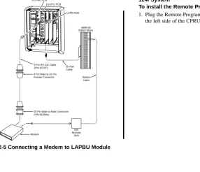
Remote Programming (LAPBU) Modules
(Figure 2-3 and 2-4)
You’ll need the Remote Programming Module if you want to use the PC Program with your system.
Figure 2-3 124i EXCPRU AND LAPBU MODULES
9 2 0 0 1 - 4 0
Advanced Feature Module (EXCPRU) Remote
Programming Module (LAPBU)
2-7
INSTALLING PCBs
28i System (Figure 2-4)
The default settings for this card are: 9600 bps, Start bit=1, Stop bit=1, Parity=No, Character=8 bit. The software requires the baud rate be set to 9600 bps, so this item is fixed and can not be changed.
To install the Remote Programming (LAPBU) Module:
1. Plug the Remote Programming Module into the header on the CPRU PCB. The connector labeled CPRU on the LAPBU module plugs into the LAPBU connector on the CPRU. 2. Connect the DIN-to-9 pin RS-232 cable (P/N 92707) to the
28i’s LAPB card. Refer to Figure 2-4.
This card provides an 8-pin connector for the cable.
3. The opposite end of the cable is connected to the COM port on your PC.
Note that for the 28i PC Program, the modem initialize
com-mand must be entered as ATD#*#* (The 124i system
requires an entry of ATDT#*#*.).
Figure 2-4 28i LAPBU MODULE
92700 - 02
RSCN
CPRU
DIN Connector for RS-232 Cable (Used for PC Programming)
INSTALLING PCBs
2. PCB Installation and Startup
2-8
Figure 2-5 Connecting a Modem to LAPBU Module
124i System
To install the Remote Programming (LAPBU) Module:
1. Plug the Remote Programming Module into the headers on the left side of the CPRU PCB as shown in Figure 2-3.
92700 - 16
25 Pin Male-to-Male Connector (P/N 92268A)
Modem
625 Modular
Jack 9 Pin Male-to-25 Pin
Female Connector 9 Pin RS-232 Cable (P/N 92707) 25-Pair
Cable 8 CPRU PCB
LAPB PCB 8 DSTU PCB
2-9
INSTALLING PCBs
28i System: Central Processing Unit (CPRU)
PCB (Figure 2-6)
Plug the CPRU PCB into the CPRU slot (Slot 1) in the KSU. The CPRU provides:
●The system’s central processing, stored program and memory for the customer’s site-specific data.
●Mode switch for cold (default data) start on power-up.
●Reset switch to allow the system to be reset without powering down.
●Battery for short term (14 day) backup of the customer’s site-specific data.
●Music on Hold jumper which allows you to select an external or internal source for Music on Hold.
●Volume Control for Music on Hold.
●DDK connectors for external Music on Hold/Background music source. The MOH music source can optionally be internal or connected to a 3-ACI Module. Refer to Music on
Hold in the Software Manual for more.
●DDK connectors for eight digital telephones, VAU, 3-ACI, 3-DCI, or 2-OPX modules.
●An additional connector for the DIM-U diagnostic unit. Figure 2-6 CPRU PCB
92700 - 03
Power On DIMU
Connector Processor
Battery
Internal MOH Enabled
External MOH Enabled
MOH Volume Control
External Music on Hold Input Digital Stations 1-8
LAPB Connector
Reset Switch
INSTALLING PCBs
2. PCB Installation and Startup
2-10
To install the 28i system’s CPRU PCB:
1. Insert the battery into the battery clips.
2. Plug the CPRU into KSU CPRU slot (Slot 1).
3. When powering up, hold down the COLD switch on the CPRU.
This ensures that the system will load the default data-base on initial power-up.
On initial power up (with a cold startup), the system scans for
station ports from the lowest slot to the highest slot, so the first 8 station ports on the 24CPRU are assigned extension numbers 301-308 automatically. The next station card that follows, no matter which slot it’s in, starts at extension 309.
2-11
INSTALLING PCBs
124i System: Central Processing Unit (CPRU)
PCB (Figure 2-7)
Plug the CPRU PCB into the CPRU slot in the Main Cabinet. The CPRU provides:
● The system’s central processing, stored program and memory for the customer’s site-specific data.
● Mode switch for hot (customer data) or cold (default data) start on power-up.
● Battery for short term (14 day) backup of the customer’s site-specific data.
● Music on Hold jumper which allows you to select an exter-nal or interexter-nal source for Music on Hold.
● Volume Controls for Music on Hold and Background Music.
● DDK connectors for external Background Music or Music on Hold music sources. The MOH music source can optionally be internal or connected to a 3-ACI Module. Refer to Music
on Hold in the Software Manual for more.
● An additional connector for the DIM-U diagnostic unit.
INSTALLING PCBs
2. PCB Installation and Startup
2-12
To install the 124i system’s CPRU PCB:
1. Slide the Mode Switch to the Cold position.
This ensures that the system will load the default data-base on initial power-up. After initial power-up, you must change the Mode Switch to Hot.
2. Insert the battery into the battery clips.
3. Plug the CPRU into Main Cabinet CPRU slot.
2-13
INSTALLING PCBs
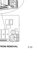
Upgrading CPRU Firmware (Figure 2-8, 2-9)
Use these instructions when upgrading the Software EPROMs on the CPRU PCB. The new EPROMs in the upgrade kit are static-sensitive components. Be sure to follow the instructions below carefully. Failure to follow proper anti-static
precau-tions could damage your new software.
To upgrade CPRU Firmware:
1. Attach a grounded wrist strap to your wrist and a grounded metal object (such as CEU ground).
2. If the system is currently powered up, unplug the system in the following order - main cabinet, first expansion cabinet, then the second expansion cabinet.
3. Lay the CPRU PCB on a flat, anti-static surface oriented as shown in Figure 2-8.
4. Using an IC puller, carefully remove the old EPROMs. Be careful not to rock the EPROMs or bend the pins during removal.
Remove all the EPROMs. Depending on your CPRU, there may be either two or four EPROMs.
5. Remove the new EPROMs from the anti-static sleeve. Save all the packaging.
Figure 2-8 CPRU EPROM REMOVAL
92001
-38
Grounded wrist strap
INSTALLING PCBs
2. PCB Installation and Startup
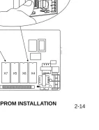
2-14 6. Following Figure 2-9, carefully install the new EPROMs.
●The EPROMs install in non-consecutive order. Be
sure to install all four EPROMs.
●Pay careful attention to line up the notch in each
EPROM with the notch in its socket.
●Do not bend any pins when plugging in the
EPROMs.
7. Reinstall the CPRU PCB. If the system has been previously installed, plug the system back in. Otherwise, continue with the installation.
8. Store old EPROMs in the anti-static sleeve.
9. Insert the sleeve into the upgrade packaging and return to: Nitsuko America
4 Forest Parkway Shelton, CT 06484 Attn: Technical Service
Figure 2-9 CPRU EPROM INSTALLATION
92001
-39
X7 X5 X6 X4
Grounded wrist strap
2-15
INSTALLING PCBs
Digital Station (DSTU) PCB (Figure 2-10)
The Digital Station (DSTU) PCB provides DDK connectors for eight digital telephones, VAU, 3-ACI, 2-DCI, or 2-OPX modules.
To install a DSTU PCB:
1. 28i: Plug a DSTU PCB into slot 2 in the KSU (1 DSTU PCB maximum per system).
124i: Plug DSTU PCBs into slots 1-3 in any installed
cabi-net (nine maximum).
2. Refer to Part 3: Installing Extensions and Trunks for cabling instructions.
On initial power-up (28i: hold down the Cold Start switch / 124i: CPRU Mode Switch set to Cold), the slot into which you
plug a station PCB determines its associated extension num-bers. The system scans for station PCBs from the lowest slot in the first cabinet (Main) to the high slot in the last cabinet (Expansion # 2). The first station PCB the system finds gets extension numbers 301-308. The next slot gets extension num-bers 309-316, etc.
After initial power up (28i Hot Start without holding down any
switch / 124i: CPRU Mode Switch set to Hot), any new station PCBs you plug in automatically add to the top of your
exten-sion number list. For example, if your highest extenexten-sion port is 324, any new station PCB you plug in will start with extension number 325. This is true regardless of the slot number used.
Figure 2-10 DIGITAL STATION (DSTU) PCB
9 2 0 0 1 - 3 3
Digital Station (DSTU) PCB
INSTALLING PCBs
2. PCB Installation and Startup
2-16
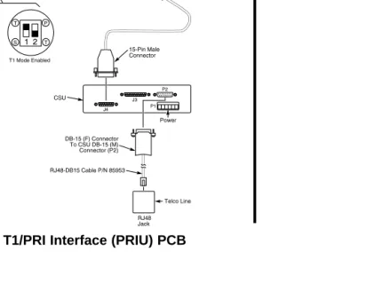
T1/PRI (PRIU) Interface PCB (Figure 2-11)
Note: For PRI, please consult with your Nitsuko
Representative for availability.
For T1 and ISDN Primary Rate Interface (PRI) applications, install a T1/PRI Interface PCB. This PCB has a single 24-channel circuit which can be configured for either T1 trunks or PRI. The T1/PRI PCB requires an Advanced Features Module (EXCPRU) and, for DTMF receivers, a Tone Detector (DTDU) PCB.
If set for T1, the T1/PRI PCB provides 24 trunks in a single slot. These trunks can be one of the following:
● Loop Start
● Ground Start
● DID
● Tie Lines
● ANI/DNIS Tie Lines
If set for PRI, each T1/PRI PCB provides 24 PRI (23 B&D) channels and supports the following PRI services:
● Basic PRI Call Control (BCC)
● Display of incoming caller’s name and number
● Routing based on the number the caller dials
● ISDN maintenance functions (e.g., In Service/Out of Service Messaging)
● Speech and 3.1 KHz audio
The T1 feature requires that the Base CPU version level must be one of the following:
3.3B 3.3C 3.4B 3.4C 4.3B 4.3C 4.6C 7.0 7.1 7.2 7.3 8.0 or higher
The version number should not be confused with the software revision. This version number will be stamped on the CPU cir-cuit board. If the Base CPU version level is anything other than the levels shown above, the T1 will not operate correctly.
The T1/PRI Interface PCB also requires the CSU or CSU/DSU equipment and interconnecting cables listed below:
● T-Serve II CSU consisting of:
- T-Serve II CSU P/N 85950)
- T-Serve II Power Supply (P/N 85951) - CSU/DSU RJ48-DB15 Cable (P/N 85953) - T1/PRI Installation Cable (P/N 92067)
2-17
INSTALLING PCBs
● Quad Datasmart DSU consisting of:
- Quad Datasmart DSU (P/N 85956)
- CSU/DSU DB15M-DB15F Cable (P/N 85952) - CSU/DSU RJ48-DB15 Cable (P/N 85953) - T1/PRI Installation Cable (P/N 92067)
The T1/PRI Interface PCB is designed to use the last available group of 24 consecutive trunks.
To install a T1/PRI Interface PCB:
1. Set the switches on the T1/PRI Interface PCB for either PRI Mode or T1 Mode.
2. Plug the T1/PRI Interface PCB into slot 3 of any cabinet (two maximum).
3. Connect the T1/PRI Installation Cable (P/N 92067) to the 4-wire DDK connector on the T1/PRI Interface PCB.
4. If connecting a CSU:
-- Connect the opposite end of the T1/PRI cable to the DB-15 female connector (J4) on the CSU.
-- Connect the DB-15 female connector on the RJ48-DB15 Cable (P/N 85953) to the DB-15 male connector (P2) on the CSU.
-- Connect the opposite end of the RJ48-DB15 cable to the
telco connection.
OR
4. If connecting a DSU:
-- Connect the opposite end of the T1/PRI cable to the DB-15 female connector (TERMINAL) on the DSU.
-- Connect the DB-15 female connector on the RJ48-DB15 Cable (P/N 85953) to the DB-15 male connector (NETWORK) on the DSU.
INSTALLING PCBs
2. PCB Installation and Startup
2-18
Figure 2-11 T1/PRI Interface (PRIU) PCB
4 3 2 1
2-19
INSTALLING PCBs
T1 to T1 Cable Pin Out (Figure 2-12)
When making a cable for T1 to T1 connections, using a DB-15 female to DB-15 female cable, the pin out should be made according to the information below. The example is shown with the 384i system, but the pin out information is the same for the 124i system.
The remaining pins have no connection. This cable may only be used in tying two T1 cards together locally. It CAN NOT be used to tie two T1 cards together through the central office.
Figure 2-12 T1 to T1 Cable Pin Out
3 1 11 9
9200 - 266
3 1 11 9 DB-15 Female Connector
384i System
T1 Card
384i System Pin 1
Pin 3 Pin 9 Pin 11
to
DB-15 Female Connector Pin 3 Pin 1 Pin 11 Pin 9
INSTALLING PCBs
2. PCB Installation and Startup
2-20
BRI (BRIU) Interface PCB (Figure 2-13, 2-14)
Note: For BRI, please consult with your Nitsuko
Representative for availability.
The BRI (BRIU) PCB provides two 2-channel circuits for con-necting to ISDN BRI services. Supported BRI services are:
● Basic BRI Call Control (BCC)
● Point-to-Point BRI Terminal Connection (no daisy-chaining)
● Multipoint BRI Terminal Connection (daisy-chaining)
The BRI Interface PCB has two circuit status LEDs on the out-board edge of the card. An additional LED shows when the PCB is in or out of service.
The BRI Interface PCB connects to the network via an NT1 Network Termination. Each PCB uses up 4 trunk ports.
To install a BRI Interface PCB:
1. Set the switches on the BRI PCB for either S-Bus or T-Bus use.
2. 28i: Plug BRI PCBs into slots 2-5 in the KSU (4 trunk PCBs maximum per system).
124i: Plug the BRI PCB into slots 4-8 slots of any installed
cabinet (15 maximum).
3. Connect an 8-pin line cord to the BRI PCB. See the figure below for the line cord connection. Connect the opposite end to the NT1 Network Termination Connection.
Figure 2-13 8-Pin Line Cord
4. Connect a line cord from the NT1 Network Termination to the telco BRI line.
Pin 8 - Grey Pin 7 - Orange Pin 6 - Black Pin 5 - Red Pin 4 - Green Pin 3 - Yellow Pin 2 - Blue Pin 1 - Brown
Pin 1 - Brown Pin 2 - Blue Pin 3 - Yellow Pin 4 - Green Pin 5 - Red Pin 6 - Black Pin 7 - Orange Pin 8 - Grey
8-Pin Line Cord Connections
2-21
INSTALLING PCBs
Figure 2-14 BRI Interface T-Bus Point-to-Point
926 - 80
TO TELCO BRI line Terminal Terminal Line
8-Pin Line Cord
(Normally On) Sync LED Circuit 1
Circuit 1
Circuit 2
(Normally On) Sync LED Circuit 2
(Normally Flashing) Status LED
Selected S-Bus
Selected T-Bus
Circuit 2 Circuit 1
Typical T-Bus Point-to-Point Configuration
INSTALLING PCBs
2. PCB Installation and Startup
2-22
Analog Station (ASTU) PCB (Figure 2-15)
The Analog Station (ASTU) PCB provides DDK connectors for four analog telephones, fax machines, voice mail ports, or modems.
28i System
The 28i system allows for a maximum of 2 4ASTU to be installed. The system automatically designates 8 ports for the 4ASTU, but only uses 4 of them. Therefore, the next slot will start with the following group of 8. For example, if the 4ASTU is installed in slot 2 (ports 309-312), slot 3 will start with port 317. This provides the system with a maximum of 8 analog ports.
124i System
When installing an ASTU PCB in slots 1-3 in any cabinet of the 124i system, the system automatically designates 8 ports for the ASTU, but only uses 4 of them. Therefore, the next slot will start with the following group of 8. For example, if the ASTU is installed in slot 2 (ports 309-312) in the first cabinet, slot 3 will start with port 317.
The ASTU PCB can provide a maximum of 72 analog ports. The analog ports can be configured as follows:
14 ASTU’s with 2 DSTU’s and 8 72 ports 2-OPX Modules
15 ASTU’s with a DSTU installed 60 ports 16 ASTU’s without a DSTU installed * 64 ports
To reach these maximums, the ASTU’s must be installed in slots 4-8 in the three cabinets. If using 16 ASTU’s, the last PCB is installed in slots 1, 2, or 3.
* It is possible, but not recommended for most customer sites,
to have up to 64 analog ports using 16 ASTU PCBs. With this configuration, there can not be a DSTU PCB installed, which is required for system programming.
2-23
INSTALLING PCBs
To install an ASTU PCB:
1. 28i: Plug 4ASTU PCBs into slots 2-5 in the KSU (2 station PCBs maximum per system).
124i: Plug ASTU PCBs into slots 1-8 in any installed
cabi-net (15 maximum with DSTU installed/16 without DSTU installed).
2. Refer to Part 3: Installing Extensions and Trunks for cabling instructions.
Figure 2-15 ANALOG STATION (ASTU) PCB
Analog Station (ASTU) PCB
Status LED
Analog Station 4 Analog Station 3 Analog Station 2 Analog Station 1
92001
INSTALLING PCBs
2. PCB Installation and Startup
2-24
Analog Trunk (ATRU) PCB (Figure 2-16)
The Analog Trunk (ATRU) PCB provides DDK connectors for four analog trunks and a Power Failure Telephone.
To install an ATRU PCB:
1. 28i: Plug 4ATRU PCBs into slots 2-5 in the KSU (4 trunk PCBs maximum per system).
124i: Plug ATRU PCBs into slots 1-8 in any installed
cabi-net (13 maximum).
2. Refer to Part 3: Installing Extensions and Trunks for cabling instructions. Refer to Part 4: Installing Optional Equipment for instructions on connecting the Power Failure Telephone.
On initial power-up with a cold start (28i: hold down the
Cold Start switch / 124i: CPRU Mode Switch set to Cold), the slot into which you plug a trunk PCB determines its associat-ed trunk numbers. The system scans for trunk PCBs from the lowest slot in the first cabinet (Main) to the highest slot in the last cabinet (Expansion # 2). The first trunk PCB the system finds gets trunk numbers 1-4. The next slot gets trunk num-bers 5-8, etc.
After initial power up (28i Hot Start without holding down any
switch / 124i: CPRU Mode Switch set to Hot), any new trunk
PCBs you plug in automatically add to the top of your trunk number list. For example, if your highest trunk port is 8, any new trunk PCB you plug in will start with trunk number 9. This is true regardless of the slot number used.
Figure 2-16 ANALOG TRUNK (ATRU) PCB
Status LED
Fuses for Trunk Protection
Power Failure Telephone
Trunk 4 Trunk 3 Trunk 2 Trunk 1
Analog Trunk (ATRU) PCB
2-25
INSTALLING PCBs
Caller ID (4CIDU) Daughter Board (Figure 2-17)
The Caller ID daughter board allows the system to display Caller ID information. Each daughter board is installed on a 4ATRU PCB. The Caller ID PCB provides Caller ID capability for all four trunk circuits on the 4ATRU PCB. Every 4ATRU PCB installed in the system can have a Caller ID daughter board attached. With the Caller ID daughter board plugged in, the 4ATRU PCB can not have ground start operation. On the 28i, the maximum number of PCBs allowed per system is 4. For the 124i, the maximum number of PCBs per system is 13.
To install an ATRU PCB:
1. Remove the 4ATRU PCB.
2. Align the Caller ID PCB standoffs over the holes located in the 4ATRU PCB.
The CN2 connector on the Caller ID PCB should be above the CN4 connector on the 4ATRU PCB and CN1 should be above CN5.
3. Push the PCB down until the standoffs snap into place.
4. Plug the 4ATRU PCB back into the system cabinet.
INSTALLING PCBs
2. PCB Installation and Startup
2-26
Ground Start (4GSAU) Daughter Board (Figure 2-18)
The Ground Start daughter boards convert the four analog loop trunks on each 4ATRU into ground start trunks. The Ground Start daughter board is installed on the 4ATRU PCB. It is possi-ble, but not required, that every 4ATRU PCB in the system can have a Ground Start PCB.
Important Notes:
● If you install a Ground Start PCB on a 4ATRU PCB, the trunk ports associated with that card can not have Caller ID.
● When a Ground Start PCB is installed on a 4ATRU PCB, all the trunk ports on that card must be ground start trunks. It is not possible to mix loop start and ground start trunks on the same card.
● The Ground Start PCB is polarity sensitive and requires the tip and ring to be connected properly.
To install a Ground Start PCB:
1. Remove the 4ATRU PCB.
2. Align the Ground Start PCB standoffs over the holes located in the 4ATRU PCB.
The J1 connector on the Ground Start PCB should be
above the CN4 connector on the 4ATRU PCB and J3 should be above CN5.
3. Push the PCB down until the standoffs snap into place.
4. Plug the 4ATRU PCB back into the system cabinet.
2-27
INSTALLING PCBs
Figure 2-18 GROUND START (4GSAU) PCB
P/N 82492
1 2
1 2
1 2
1 2
92001 - 70
CN2
CN4
CN1
CN5 Push PCB down until standoffs
INSTALLING PCBs
2. PCB Installation and Startup
2-28
E&M Tie Line (2EMTU) PCB (Figure 2-19)
The Tie Line (2EMTU) PCB supports system connections to 2-wire Type 1 (four conductor), 2-2-wire Type 2 (6 conductor), or 4-wire (four conductor) E&M signaling tie lines. Each 2EMTU PCB provides two 4-circuit tie line trunk interfaces and an on-board power supply. The strapping option on the PCB allows the use of either Type 1 or Type 2 signaling.
The Tie Line PCB requires the use of an EXCPRU daughter board and a DTDU PCB installed in the first cabinet.
To install a Tie Line PCB:
1. Set the strapping options on the 2EMTU PCB as required (see Figure 2-19).
2. Plug the 2EMTU PCB in slots 4-8 in any installed 124i cabinet (13 maximum).
3. Refer to Part 3: Installing Extensions and Trunks for cabling instructions.
Figure 2-19 TIE LINE (2EMTU) PCB
P/N 82492
1 2
1 2
1 2
2-29
INSTALLING PCBs
DID (2DIDU) PCB (Figure 2-20)
The DID (2DIDU) PCB supports two Direct Inward Dialing (DID) trunk circuits. The PCB has an on-board power supply and an LED that shows when the PCB is in or out of service. The DID PCB requires a DTDU PCB for DTMF receivers.
For the 28i system, please check with your Sales Representative for availability of this feature.
To install a DID PCB:
1. 28i: Plug DID PCBs into slots 2-5 in the KSU (4 trunk PCBs maximum per system).
124i: Plug the 2DIDU PCB in slots 4-8 in any installed
cabinet (13 maximum).
2. Refer to Part 3: Installing Extensions and Trunks for cabling instructions.
INSTALLING PCBs
2. PCB Installation and Startup
2-30
Page/Door Box (PGDU) PCB (Figure 2-21)
The Page/Door Box (PGDU) PCB provides:
● DDK connectors for four External Paging Zones or Door Boxes.
● Selector switches to enable each port for External Paging or Door Box. Each of the four PCB ports can be either an External Paging port or a Door Box port - not both.
● DDK connectors for four dry contact External Paging control relays (one for each zone). These contacts can control a cus-tomer-provided Paging amplifier or an entrance door strike.
● Volume controls for each External Paging/Door Box circuit.
● DDK connectors for four alarm/fax sensors.
To install a PGDU PCB:
1. 28i: Plug PGDU PCBs into slots 2-5 in the KSU (2 PCBs maximum per system).
124i: Plug PGDU PCBs into slots 4-8 in any installed
cabinet (2 maximum).
2. Refer to Part 4: Installing Optional Equipment for more on installing Door Boxes, External Paging equipment and alarm/fax sensors.
Figure 2-21 PAGE/DOOR BOX (PGDU) PCB
92001
-35
Page/Door Box (PGDU) PCB Mode Switches
for each circuit
Door Box / External Page Volume Controls DH CN3 CN4 DH DH DH PG PG PG PG 1 2 3 4 VR1 Alarm 1 Alarm 2 Alarm 3 Alarm 4
Door Box 4 - External Page 4
Door Box 3 - External Page 3
Door Box 2 - External Page 2
Door Box 1 - External Page 1 Control Relay 4
Control Relay 3
Control Relay 2
Control Relay 1
VR2 VR3 VR4
2-31
On initial power-up (with the CPRU performing a Cold Start),
the slot into which you plug a PGDU PCB determines its asso-ciated External Paging and/or Door Box numbers. The system scans the slots in order (Slots 2-5 in the 28i, Slots 4-8 in the 124i) for PGDU PCBs starting with the first cabinet (Main) and ending with the last cabinet (Expansion # 2), if applicable. The first PGDU PCB the system finds gets the lower-numbered External Paging Zones/Door Boxes. For example, if configured for Door Boxes, the first PCB would have Door Boxes 1-4, while the second PCB would have Door Boxes 5-8.
After initial power up (with the CPRU performing a Hot
Start), a new PGDU PCB you plug in automatically adds to the top of your External Paging/Door Box list. For example, if you already have Door Boxes 1-4, the new PCB you plug in will start with Door Box 5. This is true regardless of the slot number used.
2. PCB Installation and Startup
2-32
Tone Detector (DTDU) PCB (Figure 2-22)
The Tone Detector (DTDU) PCB provides outbound dial tone detection for Off Premise Extensions and analog trunks. It also provides DTMF receivers for certain types of inbound trunks. These include:
● DTMF DIDs
● DTMF E&M Tie Lines
● DISA
● T1 DNIS
● T1 DID
● T1 Tie Lines
To install a DTDU PCBs:
1. 28i: Plug DTDU PCBs into slots 2-5 in the KSU (2 trunk PCBs maximum per system).
124i: Plug DTDU PCBs into slots 4-8 in any installed
cabinet (2 maximum).
Figure 2-22 TONE DETECTOR (DTDU) PCB
9 2 0 0 1 - 3 4
Tone Detector (DTDU) PCB
Status LED
2-33
INSTALLING PCBs
28i Power-Up Sequence
Now that all the PCBs you need are installed, you can power-up the system.
1. Install a surge protector in the AC outlet you intend to use for system power.
2. Plug the AC power cord for the KSU into its surge protector.
System LEDs on Power-Up
PCB
LED
Status
CPRU Power-On Lights (green) when KSU plugged in
Processor LED Flashes slowly (red) about 10 seconds after power-up ASTU Status LED Flashes slowly (red) when
PCB activated (on-line)
2. PCB Installation and Startup
2-34
INSTALLING PCBs
124i Power-Up Sequence
Now that all the PCBs you need are installed, you can power-up the system.
1. Install surge protectors in the AC outlets you intend to use for system power.
2. Plug the AC power cord for Expansion Cabinet # 2 into its surge protector.
3. Plug the AC power cord for Expansion Cabinet # 1 into its surge protector.
4. Plug the AC power cord for the Main Cabinet into its surge protector.
System LEDs on Power-Up
PCB
LED
Status
CPRU Power-On Lights (green) when Main Cabinet plugged in Processor LED Flashes slowly (red) about
10 seconds after power-up ASTU Status LED Flashes slowly (red) when
PCB activated (on-line)
The power supply in the 124i cabinet uses two 4 amp fast-blow fuses. If the system does not power up at this point, the problem could be with the fuses. The fuses can be replaced by carefully removing them from the holding clips.
Figure 2-23 FUSE REPLACEMENT
4 amp fast blow fuses
2-35
INSTALLING PCBs
Upgrading the Advanced Feature (EXCPRU)
Module Software Version for the 124i System
(Figure 2-24 and 2-25)
The PC Card (P/N 92050xxx) is used to upgrade the 124i EXCPRU. The following instructions should be followed care-fully.
Note: To keep the customer’s information, set the mode switch
on the CPRU to the “HOT” position. Otherwise, the sys-tem will default.
1. Make sure the system is unplugged and the cover from the main cabinet has been removed.
2. Attach a grounded wrist strap to your wrist and a grounded metal object (such as the CEU ground).
3. Carefully install the PC card into the designated slot on the EXCPRU.
Make sure the card is completely installed - it should be flush with the Eject button (see Figure 2-24).
4. Set the switch on the EXCPRU to position 2 and reinstall the CPRU.
5. Power up the system.
6. When the system reset is complete, carefully set the switch on the EXCPRU back to position 1.
The system will briefly reset (approximately 15 seconds).
7. Unplug the system again and remove the PC Card.
The CPRU will move and can slip out of it’s slot. Make sure the CPRU is installed properly before proceeding.
8. Replace the cover on the main cabinet and power up the system.
9. To make sure the upgrade was successful, enter the pro-gramming mode by pressing CALL1 + #*#*. The new software version should appear on the upper right corner of the display keyset.
INSTALLING PCBs
2. PCB Installation and Startup
2-36
Figure 2-24 PC CARD INSTALLATION
Figure 2-25 PC CARD AND EXCPRU LOCATION
92001 - 65
(EXCPRU) 92025 9 2 0 01 - 6 4
Insert
92050** PC Card Position 1
1
Position 2
1
Should be flush
PC Card
In this section . . . .Page
Connecting Blocks . . . .3-2
Working With DDK Connectors . . . 3-2 Punching Down a DDK Installation Cable . . . 3-2
Connecting Extensions . . . .3-5
Digital Station (DSTU) Connections. . . 3-5 Analog Station (ASTU) Connections . . . 3-7
Connecting Trunks . . . .3-9
Analog Trunk (ATRU) PCB Connections . . . . 3-9 Tie Line Trunk (2EMTU) PCB Connections . 3-11 DID Trunk (2DIDU) PCB Connections. . . 3-12
3-1
Section 3, INSTALLING EXTENSIONS AND TRUNKS
3. Installing Extensions and Trunks
3-2
CONNECTING BLOCKS
Working With DDK Connectors
The system uses DDK type connectors for extensions, trunks and optional equipment. Using the 25-pair DDK Installation Cables (P/N 93090) that came with your system makes it easy to connect the PCBs to standard 66M1-50 connecting blocks. In general, each cabinet needs:
● One 66M1-50 block and DDK Installation Cable for exten-sions and optional equipment.
● One 66M1-50 block and DDK Installation Cable for trunks.
Note: Depending on your PCB configuration and local codes,
you may need an additional 66M1-50 block and DDK Installation Cable for optional equipment.
Punching Down a DDK Installation Cable
(Figures 3-1, 3-2, 3-3)
The DDK Installation Cables have DDK connectors installed (in pairs) on one end and are unterminated on the other. 1. For each 66M1-50 block, punch down the DDK Installation
Cable in standard color-code order.
Refer to Figure 3-4 if you need help with the color code.
2. As you use the following pages to install extensions, trunks and optional equipment, write down the circuit assignments in Figure 3-4.
Make additional copies of Figure 3-4 as required.
3-3
CONNECTING BLOCKS
Figure 3-1 PUNCHING DOWN DDK INSTALLATION CABLES
Figure 3-2 SECURING Figure 3-3 SECURING
THE CABLES ON THE 28i THE CABLES ON THE 124i
926 - 47
66M1-50 Connecting
Block WHT-BLU
BLU-WHT WHT-ORN
ORN-WHT WHT-GRN
GRN-WHT
WHT-BLU BLU-WHT WHT-ORN ORN-WHT WHT-GRN GRN-WHT
3. Installing
Extensions and T
runks 3-4
CONNECTING BLOCKS
BLOCK TERM COLOR CODE FUNCTION 25-PAIR CABLE9 2 6 - 3 9
1 2 3 4 5 6 7 8 9 10 11 12 13 14 15 16 17 18 19 20 21 22 23 24 25 26 27 28 29 30 41 42 43 44 45 46 47 48 49 50 31 32 33 34 35 36 37 38 39 40 WHT-BLU BLU-WHT WHT-ORN ORN-WHT WHT GRN GRN-WHT WHT-BRN BRN-WHT WHT-SLT SLT-WHT RED-BLU BLU-RED RED-ORN ORN-RED RED-GRN GRN-RED RED-BRN BRN-RED RED-SLT SLT-RED BLK-BLU BLU-BLK BLK-ORN ORN-BLK BLK-GRN GRN-BLK BLK-BRN BRN-BLK BLK-SLT SLT-BLK YEL-BLU BLU-YEL YEL-ORN ORN-YEL YEL-GRN GRN-YEL YEL-BRN BRN-YEL YEL-SLT SLT-YEL VIO-BLU BLU-VIO VIO-ORN ORN-VIO VIO-GRN GRN-VIO VIO-BRN BRN-VIO VIO-SLT SLT-VIO
3-5
CONNECTING EXTENSIONS
Digital Station (DSTU) PCB Connections (Figure 3-5)
The Digital Station PCB has DDK connectors for eight stations.
Figure 3-5 DIGITAL STATION CONNECTIONS
1. Following the conventional color code, insert the DDK con-nectors into the PCB. For example, the first DSTU in the system would have these connections:
Extension Port DDK Conn Pair
301 1 WHT-BLU / BLU-WHT
302 2 WHT-ORN / ORN-WHT
303 3 WHT-GRN / GRN-WHT
304 4 WHT-BRN / BRN WHT
305 5 WHT-SLT / SLT-WHT
306 6 RED-BLU / BLU-RED
307 7 RED-ORN / ORN-RED
308 8 RED-GRN / GRN-RED
Write down the connections for each DSTU PCB in Figure 3-4. Make additional copies of Figure 3-5 as required.
2. Install a modular jack for each digital extension within six feet of the telephone’s location. See Figure 3-6.
3. For each digital extension, run one-pair 24 AWG station cable from the cross-connect block to the modular jack.
4. Terminate the station cable WHT/BLU - BLU/WHT leads to the RED and GRN lugs in the modular jack.
Continued on next page. . . 9 2 0 0 1 - 3 3
Digital Station (DSTU) PCB
3. Installing Extensions and Trunks
3-6
CONNECTING EXTENSIONS
Digital Station (DSTU) PCB Connections (Cont’d)
5. Back at the MDF, run one pair of cross-connect wire between the pins on the B block and cross-connect block to complete the connection.
6. Install bridging clips as required.
7. After completing step 6, you should be able to place and answer calls at the extension.
8. Record your entries on Figure 3-4.
Figure 3-6 CONNECTING DIGITAL TELEPHONES 625
Modular Jack
25-Pair DDK Installation Cable
BLK YEL
RED GRN
BLU-WHT WHT-BLU
926 - 44
Cross Connect
Block One-Pair Cross Connect
3-7
CONNECTING EXTENSIONS
Analog Station (ASTU) Connections (Figure 3-7)
The Analog Station PCB has DDK connectors for four sta-tions. The 28i system allows for a maximum of 2 ASTU’s to be installed. On a 124i system, the maximum allowed is either 15 ASTU PCB’s with a DSTU PCB installed in slot 1, 2, or 3 (providing 60 analog station ports and 8 digital station ports)
OR 16 ASTU PCB’s with no DSTU PCB installed in the
sys-tem (providing 64 analog station ports). Note: A DSTU PCB must be installed when access to system programming is required.
Figure 3-7 Analog Station (ASTU) Connections
1. Following the conventional color code, insert the DDK con-nectors into the PCB. For example, if the ASTU PCB is the second Station PCB (and a DSTU is the first), the ASTU PCB would have these connections:
Extension Port DDK Conn. Pair
309 9 RED-BRN / BRN-RED
310 10 RED-SLT / SLT-RED
311 11 BLK-BLU / BLU-BLK
312 12 BLK-ORN / ORN-BLK
Write down the connections for each ASTU PCB in Figure 3-4. Make additional copies of Figure 3-4 as required.
2. Install a modular jack for each analog extension within six feet of the telephone’s location. See Figure 3-8.
3. For each analog extension, run one-pair 24 AWG station cable from the cross-connect block to the modular jack.
4. Terminate the station cable WHT/BLU - BLU/WHT leads to the RED and GRN lugs in the modular jack.
Continued on next page . . . Analog Station (ASTU) PCB
Status LED
Analog Station 4 Analog Station 3 Analog Station 2 Analog Station 1
92001
3. Installing Extensions and Trunks
3-8
CONNECTING EXTENSIONS
Analog Station (ASTU) Connections (Cont’d)
5. Back at the MDF, run one pair of cross-connect wire between the pins on the B block and cross-connect block to complete the connection.
6. Install bridging clips as required.
7. After completing step 6, you should be able to place and answer calls at the extension.
8. Record your entries on Figure 3-4.
Figure 3-8 CONNECTING ANALOG TELEPHONES 625
Modular Jack
25-Pair DDK Installation Cable
BLK YEL
RED GRN
BLU-WHT WHT-BLU
926 - 45
Cross Connect
Block One-Pair Cross Connect
3-9
CONNECTING TRUNKS
Analog Trunk (ATRU) PCB Connections (Figure 3-9)
The Analog Trunk PCB has DDK connectors for four loop start CO trunks and a power failure telephone.
Refer to Part 4: Installing Optional Equipment for instructions on connecting a power failure telephone.
Figure 3-9 ANALOG TRUNK CONNECTIONS
1. Following the conventional color code, insert the DDK con-nectors into the PCB. For example, the first ATRU in the system would have these connections:
Trunk
DDK Connector Pair
1 WHT-BLU / BLU-WHT 2 WHT-ORN / ORN-WHT 3 WHT-GRN / GRN-WHT 4 WHT-BRN / BRN WHT
Write down the connections for each ATRU PCB in Figure 3-4. Make additional copies of Figure 3-4 as required.
2. For each trunk, run one pair of cross-connect wire between the pins on the cross-connect block and the CPE (customer side) of the telco’s RJ21X (Figure 3-10 on the following page).
3. Install bridging clips as required.
Continued on next page . . . Status LED
Fuses for Trunk Protection
Power Failure Telephone
Trunk 4 Trunk 3 Trunk 2 Trunk 1
Analog Trunk (ATRU) PCB
3. Installing Extensions and Trunks
3-10
CONNECTING TRUNKS
Analog Trunk (ATRU) PCB Connections (Cont’d)
4. After completing step 3, you should be able to place and answer calls over the connected trunk.
5. Record your entries on Figure 3-4.
Figure 3-10 CONNECTING ANALOG TRUNKS 25-Pair Cable to Central Office
25-Pair DDK Installation Cable Telco
RJ21X One-Pair Cross Connect
"A" Block
3-11
CONNECTING TRUNKS
Tie Line Trunk (2EMTU) PCB Connections (Figure 3-11)
The Tie Line PCB has DDK connector for two 2-wire (Type 1) (4-conductor), two 2-wire Type 2 (6 conductor), four 4-wire (4 conductor) tie line trunks.
1. Following the conventional color code, insert the DDK con-nectors into the PCB. For example, the first 2EMTU PCB in the system would have these connections:
Trunk
DDK Connector Pair
1 WHT-BLU / BLU-WHT / WHT-ORN / ORN-WHT 2 WHT-GRN / GRN-WHT / WHT-BRN / BRN WHT
Write down the connections for each 2EMTU PCB in Figure 3-4. Make additional copies of Figure 3-4 as required.
2. For each trunk, run cross-connect wires between the pins on the cross-connect block and the CPE (customer side) of the telco’s RJ21X (Figure 3-11).
3. Install bridging clips as required.
Figure 3-11 ANALOG TRUNK CONNECTIONS
P/N 82492
1 2
1 2
1 2
3. Installing Extensions and Trunks
3-12
CONNECTING TRUNKS
DID Trunk (2DIDU) PCB Connections (Figure 3-12)
The DID PCB has DDK connector for two Direct Inward Dial (DID) trunk circuits.
1. Following the conventional color code, insert the DDK connectors into CO1 and CO2 on the PCB. For example, the first 2DIDU PCB in the system would have these connections:
Trunk
DDK Connector Pair
1 WHT-BLU (tip 1) / BLU-WHT (ring 1) 2 WHT-ORN (tip 2) / ORN-WHT (ring 2)
Write down the connections for each 2DIDU PCB in Figure 3-4. Make additional copies of Figure 3-4 as required.
2. For each trunk, run one pair of cross-connect wires between the pins on the cross-connect block and the CPE (customer side) of the telco’s RJ21X (Figure 3-12).
3. Install bridging clips as required. Figure 3-12 DID TRUNK CONNECTIONS
3-13
CONNECTING TRUNKS
Figure 3-13 DID TRUNK CONNECTIONS 25-Pair Cable to Central Office
25-Pair DDK Installation Cable Telco
RJ21X One-Pair Cross Connect
"A" Block
4. Optional Equipment
Section 4, INSTALLING OPTIONAL EQUIPMENT
In this section . . . .Page
2-OPX Module . . . .4-22
Using the 2-OPX Module . . . 4-22 Installing the 2-OPX Module . . . 4-22
VAU and Expansion Modules . . . .4-24
Using the VAU Module . . . 4-24 Installing the VAU Module . . . 4-24 Installing the Plug-in Expansion Board . . . 4-26
3-ACI Module . . . .4-27
Using the 3-ACI Module . . . 4-27 Installing the 3-ACI Module . . . 4-27 Installing the 3-ACI Module for Music
on Hold and External Paging . . . 4-28
REJ Recording Jack . . . .4-31
Using the REJ Recording Jack . . . 4-31 Installing the REJ . . . 4-31
Wall-Mount Kit . . . .4-35
Using the Wall-Mount Kit. . . 4-35 Installing the Wall-Mount Handset Hanger
for 926 Series Phones . . . 4-35
In this section . . . .Page
Alarm and Fax Sensors . . . .4-3
Using External Alarm and Fax Sensors . . . 4-3 Installing an External Alarm or
Fax Sensor Circuit . . . 4-4
External Paging and Page Relays . . . .4-6
Using External Paging . . . 4-6 Installing External Paging. . . 4-6 Installing External Paging Control Relays. . . . 4-9
Door Box . . . .4-11
Using the Door Box . . . 4-11 Installing a Door Box . . . 4-11 Installing Door Strike Control Relays . . . 4-13
Music Sources . . . .4-15
Music on Hold and Background Music . . . 4-15 Installing a Music Source on the CPRU PCB 4-15
Power Failure Telephones . . . .4-18
Power Failure Cut-Through . . . 4-18
DSS Console . . . .4-20
Using a DSS Console . . . 4-20 Installing a DSS Console . . . 4-20
4. Optional Equipment
4-2
In this section . . . .Page
Wall-Mount Kit (Cont.)
Installing the Wall-Mount Handset Hanger
for 922 Series Phones . . . 4-36 Wall-Mounting a Key Telephone on
926/922 Sereis Phones . . . 4-37 Using the Desk Stand on 926/922
Series Phones . . . 4-38 Installing the Wall-Mount Handset Hanger
4. Optional Equipment
4-3
ALARM AND FAX SENSORS
Using External Alarm and Fax Sensors
The 4PGDU PCB provides four alarm/fax circuits which you can program to detect a make or break closure from an alarm, fax machine or modem.
When a 4PGDU circuit is used for alarm . . .
An alarm detection causes the system to send a signal to sta-tions programmed to receive the alarms. The alarm signal can also be sent to external paging speakers.
When a 4PGDU is used for fax sharing . . .
Fax sharing allows system users to share a line also used by a fax machine or modem. When a fax machine or modem is using the line, the system detects the line in use, "busies" the line and sends "line busy" status to all stations with a line appearance. This prevents a station from accessing the line while in use by the modem or fax.
Note:
● The PGDU alarm/fax features require a 10-30 VDC power
supply installed in series with the alarm/fax circuit.
● The sensors are polarity sensitive and require the tip and ring
4. Optional Equipment
4-4
ALARM AND FAX SENSORS
Installing an External Alarm or Fax Sensor
Circuit (Figure 4-1)
CAUTION
Be sure the requirements of the fax machine and alarm system sensors do not exceed the system specifications.
Maximum Initial Contact Resistance: 100 mohm
1. Locate an available DDK connector in a trunk (A) block or station (B) block.
Local codes may prevent you from using a DDK con-nector on the A block for optional equipment.
2. For the DDK connector chosen, cross-connect the associated wire pair from the A or B block to the cross-connect block.
3. Connect two leads from the alarm system or fax machine sensor to the associated terminals on the cross-connect block.
4. Plug the DDK connector into the Alarm (1-4) connector on the PGDU PCB (Figure 4-2).
4. Optional Equipment
4-5
ALARM AND FAX SENSORS
Installing an External Alarm or Fax Sensor
Circuit (Cont’d)
5. Write down your connection on Figure 3-4 (page 3-4).
6. To program fax sensors . . .
With the default settings, fax sensors are disabled.
0304 - PGDU PCB Alarm/Fax Sensor Setup
Program the sensor for fax (type 2) and associate it with the trunk.
Refer to Fax Machine Compatibility in the Software Manual for additional details
To program alarm contacts . . .
With the default settings, PGDU sensors are alarm sensors set for normally open operation using alarm ring tone 1. Alarms do not alert extensions.
1010 - External Alarm Extensions
Determine which alarms should alert which extensions. For each sensor, enter 1 to ring extension or 0 to not ring exten-sion.
Refer to External Alarm Sensors in the Software Manual for
4. Optional Equipment
4-6
EXTERNAL PAGING AND PAGE RELAYS
Using External Paging
Each PGDU PCB has four External Paging audio outputs and four associated control relays. You connect the audio outputs to audio inputs on customer provided paging systems. In some paging systems, you can use the control relays to automatically turn the amplifiers on and off. The control relays are normally open and close whenever a user calls the External Paging zone.
Notes: ● The 3-ACI Analog Communications Interface can
also provide External Paging. Refer to the page 4-27 for more.
● A PGDU circuit used for External Paging cannot also be used for a Door Box.
Installing External Paging (Figure 4-3)
CAUTION
Be sure the audio input requirements of the paging equipment are compatible with the audio output specifications of the system.
Output Impedance: 600 Ohm
Output Level: Nominal 250 mV (-10 dBm)
Maximum Output: 400 mV RMS Figure 4-3 CONNECTING EXTERNAL PAGING
One-Pair Cross-Connect
DDK Connector To External Page audio output on PGDU PCB
25-Pair DDK Installation Cable
"B" Block Cross
Connect Block
Output to paging system audio inputs
4. Optional Equipment
4-7
EXTERNAL PAGING AND PAGE RELAYS
Installing External Paging (Cont’d)
1. Locate an available DDK connector in a trunk (A) block or station (B) block.
Local codes may prevent you from using a DDK con-nector on the A block for optional equipment.
2. For the DDK connector chosen, cross-connect the associated wire pair from the A or B block to the cross-connect block.
3. Connect two leads from the paging system audio inputs to the associated terminals on the cross-connect block.
4. Plug the DDK connector into the External Page (1-4) con-nector in the PGDU PCB (Figure 4-4).
5. Install bridging clips as required.
6. Make sure the switch for the paging circuit is set to PG (not DH).
7. Write down your connection on Figure 3-4.
Figure 4-4 CONNECTING TO THE PGDU
92001
-43
Page/Door Box (PGDU) PCB Mode Switches
for each circuit
Door Box / External Page Volume Controls
DH
CN3
CN4
DH
DH
DH
PG
PG
PG
PG
1 2 3 4
VR1
Door Box 4 - External Page 4
Door Box 3 - External Page 3
Door Box 2 - External Page 2
Door Box 1 - External Page 1 Control Relay 4
Control Relay 3
Control Relay 2
Control Relay 1
4. Optional Equipment
4-8
EXTERNAL PAGING AND PAGE RELAYS
Installing External Paging (Cont’d)
8. To program External Paging . . .
With the default settings,
External Paging is enabled at all extensions. The External Paging zone number is the same as the circuit number. For example, the lowest numbered paging circuit you set up is external zone 1.
Refer to Paging, External in the Software Manual for addi-tional details.
9. After programming External Paging, make a test page.
4. Optional Equipment
4-9
EXTERNAL PAGING AND PAGE RELAYS
Installing External Paging Control Relays (Figure 4-5)
CAUTION
Be sure the control circuit requirements of the paging equip-ment are compatible with the control relay output specifications of the system.
Contact Configuration: Normally open Maximum Load: 60 mA @ 30 VDC
10 mA @ 90 VDC
Maximum Initial Contact Resistance: 50 mOhms
1. Locate an available DDK connector in a trunk (A) block or station (B) block.
Local codes may prevent you from using a DDK con-nector on the A block for optional equipment.
2. For the DDK connector chosen, cross-connect the associated wire pair from the A or B block to the cross-connect block.
Figure 4-5 CONNECTING CONTROL RELAYS
Continued on next page . . . One-Pair Cross-Connect
DDK Connector To Control Relay on PGDU PCB
25-Pair DDK Installation Cable
"B" Block Cross
Connect Block
Output to paging system control inputs