Volume 2, No. 6, Nov-Dec 2011
International Journal of Advanced Research in Computer Science
RESEARCH PAPER
Available Online at www.ijarcs.info
Artificial Bee Colony Algorithm for Synthesis of Phase-only Reconfigurable Circular
Array Antenna
Banani Basu
*Department of Electronics and Communication Engineering, National Institute of Technology,
Durgapur, India [email protected]
G. K. Mahanti
Department of Electronics and Communication Engineering National Institute of Technology,
Durgapur, India [email protected]
Soham Mondal and Saheli Sarkar
Department of Electronics and Communication EngineeringNational Institute of Technology, Durgapur, India [email protected]; [email protected]
Abstract: The paper describes an optimization based design method of reconfigurable dual beam uniform circular antenna array. Artificial Bees Colony Optimization algorithm (ABC) is applied to find the set of excitation (amplitude and phase) distributions of the optimally spaced array to generate a sector pattern main beam with desired side lobe level. The same excitation amplitudes are applied to the array with zero phases that result in a pencil-shaped main beam with the same side lobe level. We presented two arrays of isotropic elements and half-wavelength dipoles. In the second example mutual coupling between the dipoles are considered and analyzed using induced EMF method. Simulation results in both the cases are in good agreement with the desired ones.
Keywords: Reconfigurable beam, Uniform Circular Array, Artificial Bees Colony Optimization Algorithm (ABC), Side lobe level, Isotropic Antenna, Half-wavelength Dipole.
I. INTRODUCTION
Multiple shaped radiation patterns are achieved utilizing different set of excitation amplitude and phase distribution. Thus it requires beam-forming network of considerable complexity. Use of common amplitude and variable phase excitation for different patterns reduces the complexity in designing feed network. There are several examples that uses phase only synthesis of multiple beams is reported in articles [1-6].
Bucci et al. [1] proposed the method of projection to synthesize reconfigurable array antennas with asymmetrical pencil and flat-top beam patterns using common amplitude and varying phase distributions. Phase only pattern synthesis method to generate multiple patterns with pre-fixed amplitude distribution using modified Woodward-Lawson technique was described in article [2]. Around the same time Diaz et al. [4] synthesized phase-differentiated multiple pattern antenna arrays using simulated annealing algorithm. Gies [4] utilized Woodward-Lawson method as well as a direct optimization technique based on particle swarm optimization for designing dual beam array. Article [5] synthesized fully digital controlled reconfigurable linear array antennas with fixed dynamic range ratio. The metaheuristic approach towards the design of reconfigurable multiple beam circular array antenna using gravitational search algorithm (GSA) is traced in article [6].
Evolutionary optimization algorithms have an extensive use in the area of antenna design problems. The uses of these optimizers are widely and clearly appreciated in antenna array synthesis. To date, different algorithms like GA, PSO, DE have
been successfully applied to different electromagnetic problems including antenna design and array synthesis. There are many published articles dealing with the synthesis of circular array using different evolutionary optimizers [7-9]. Literature [7] used evolutionary approaches like real-coded genetic algorithm (GA) for designing circular arrays with maximal side lobe level reduction under the constraint of a fixed beam width. Shihab et al. applied the particle swarm optimization (PSO) algorithm to the same problem and achieved better results as compared to those reported in [8]. Article [9] compared three powerful population-based optimization algorithms—PSO, GA, and differential evolution (DE) on the design problem of scanned circular arrays.
II. FORMULATION
We consider N isotropic antenna elements along a circle of radius r in the x-y plane with intermediate spacing d as shown
Figure.1. Uniform Circular Array of N isotropic elements
(
)
(
)
ABC is used to optimize the antenna array shown in Fig.1. For the dual-beam array optimization, the fitness function must quantify the entire array radiation pattern. The fitness function to be minimized for dual-beam array optimization problem can be expressed as follows:
The superscript p indicates the design specification for the pencil beam and the superscript f indicates the design specification for the flat-top beam pattern. The design specification of the first summation in Equation (3) includes the desired and obtained values of SLL and HPBW for the pencil beam pattern where the second summation in Equation (3) includes SLL and ripple factor for the flat-top beam pattern. The desired tolerance levels of the ripple for the sector beam pattern in the coverage region are kept at 0.5 dB from the peak value of 0 dB. Side lobe level is fixed at -20dB.
We employ ABC to calculate the current excitation distributions as well as the optimal spacing between two
consecutive elements in order to generate the reconfigurable array patterns. We start solving the problem with the position coordinates xin of the randomly chosen solution in the
algorithm. Given the values of xin (n =1, . . . , N), a
corresponding value of the fitness function fit(xi1, xi2, . . . , xi N )
is derived. ABC is applied to calculate the best position that corresponds to the minimum fitness value.
III. ARTIFICIAL BEES COLONY OPTIMIZATION
ALGORITHM
Karaboga [11] analyzes the foraging behavior of honey bee swarm and proposes a new algorithm simulating this behavior for solving multi-dimensional and multi-modal optimization problems, called Artificial Bee Colony (ABC). In the algorithm, an artificial bee colony consists of three groups of bees: employed bees, onlookers and scouts. Employed bees are associated with a particular food source, which they are currently exploiting. They carry the information about this particular source and share this information with a certain probability by waggle dance. Unemployed bees seek a food source to exploit. There are two types of unemployed bees: scouts and onlookers. Scouts search the environment for new food sources without any guidance and occasionally discover rich, entirely unknown food sources. On the other hand onlookers observe the waggle dance and so are placed on the food sources by using a probability based selection process. As the nectar amount of a food source increases, the probability value with which the food source is preferred by onlookers increases. In ABC, the first half of the colony comprises of the employed bees and the second half includes the onlookers. For every food source, there is only one employed bee. Another and the employed bee is converted to a scout.
ABC begins with randomly distributed initial population of size SN. Each solution xij (i = 1, 2, ..., SN) is a D-dimensional
is adaptively reduced. If a parameter value produced by this operation exceeds its preset limit, the parameter is reset to an acceptable value within that limit. The food source, which is abandoned by the bees, is replaced with a new food source by the scouts. The position that cannot be improved further through the predetermined number of cycles is assumed to be abandoned. The value of predetermined number of cycles is an important control parameter of the ABC algorithm and called as “limit”. The scout discovers new food source
x
ijthat isinitialized in the range of the parameter j ∈ {1, 2,...,D} is
determined using expression (4)
After the generation of the candidate source position vi,j the
fitness value associated with each solution is evaluated. If the fitness value is found better than the best fitness value achieved so far, then it goes for next cycle otherwise the old solution xij
is retained for the next generation. The probability value associated with each solution is calculated using equation (6).
∑
where fiti is the fitness value of the solution i and evaluated using eq.(7).
where Ji is the cost function value of solution i as specified in Eq.(3) .
The following control parameters are used in ABC algorithm: The number of food sources, which is equal to the number of employed or onlooker bees (SN), the value of limit and the maximum cycle number (MCN).
Steps involved in ABC are as follows:
Step1. Initialize the solutions xij randomly.
Step2. Evaluate the fitness of each population.
Step3. Produce new solution vij in the vicinity of each xij.
Step4. Calculate the probability and fitness values associated with every solution.
Step7. Memorize the best solution achieved so far.
Step8. Cycle=Cycle+1
Step9. Until cycle=MCN.
IV. RESULTS AND DISCUSSIONS FOR
CIRCULAR ARRAY OF ISOTROPIC ANTENNAS
A 24-element optimally spaced circular array antenna is studied in this article. The array elements are all identical. The desired user direction of the array beam is considered
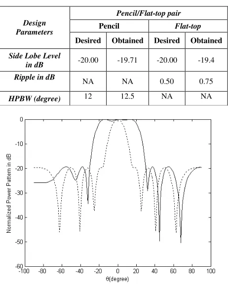
Table 1: Desired and obtained results for reconfigurable array of isotropic antennas
Pencil/Flat-top pair
Pencil Flat-top Design
Parameters
Desired Obtained Desired Obtained
Side Lobe Level
in dB -20.00 -19.71 -20.00 -19.4
Ripple in dB NA NA 0.50 0.75
HPBW (degree) 12 12.5 NA NA
Fig.2. Normalized absolute power patterns in dB for dual-beam array of isotropic antennas size and maximum cycles are chosen 40 and 1000 respectively. Thus total number of objective function evaluations becomes 40000. Other significant control parameters in ABC are limit=20 and scout production period SPP= 20.
The algorithm is designed to generate a vector of 49 real values between zero and one. The first 24 values of the vector is mapped and scaled to desired amplitude weight between 0 and 1, next 24 values of the vector are mapped and scaled to desired phase weight between -1800 to 1800 and the last value is mapped and scaled to desired intermediate spacing weight range between 0.4 to 0.8 wavelengths.
V. CIRCULAR ARRAY OFHALF- WAVELENGTH DIPOLE ANTENNAS
This section illustrates the performances of the uniform circular array of half-wavelength thin dipoles [14]. Figure 3 shows the proposed circular array geometry. Analysis of circular dipole array is the same as isotropic circular array but here the elements are dipoles. Mutual coupling has a significant impact on array pattern. Induced EMF method is used to predict the array pattern in presence of mutual coupling [15].
In optimizing circular dipole array, the parameters to be controlled are voltage excitation (amplitude and phase) of
individual array elements. The resulting feed current is given by:
I =Z−1V (8)
where V is the voltage excitation distributions used to obtain desired array pattern and Z is the impedance matrix.
Self-impedances Znn and mutual impedances Znm of Z matrix are calculated by induced emf method [14], which assume the current distribution on the dipoles to be sinusoidal.
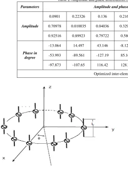
Table 2 Amplitude and phase distributions for reconfigurable array of isotropic antennas
Parameters Amplitude and phase distribution for the dual beam array
0.0901 0.22326 0.136 0.21639 0.43463 0.71257 0.76575 0.81876
0.70978 0.010035 0.04036 0.32903 0.53043 0.2187 0.24858 0.49575
Amplitude
0.92516 0.89923 0.79722 0.5804 0.28325 0.14474 0.19763 0.21772
-13.064 14.497 43.146 -8.1252 -69.196 56.358 -18.637 -60.995
-53.993 -89.561 -127.19 85.162 -83.617 -30.416 -101.65 -66.017
Phase in degree
-97.873 -107.65 116.42 128.77 -135.11 149.65 -126.56 -61.823
Optimized inter-element spacing d=0.5388
Fig.3. Uniform circular array of dipole antennas
For dual beam reconfiguration same fitness function is used as described in Eq. (3). However, desired side lobe level is fixed at -16dB in this case.
VI. RESULTS AND DISCUSSIONS FOR
CIRCULAR ARRAY OF DIPOLE ANTENNAS
A 24-element circular array antenna is studied in this article. The array elements are identical and spacing between two consecutive dipoles is fixed at 0.5
λ
. The desired user direction of the array beam is considered at(
)
(
0 0)
0
0,φ = 90 ,90
θ .
The array is optimized in order to generate a pencil beam with zero phases and a flat-top beam with variable phases. Both the patterns are optimized in θ=900 plane.
ABC algorithm with the similar parametric settings as used in case of isotropic sources is applied to optimize the proposed array.
The algorithm is designed to generate a vector of 48 real values between zero and one. The first 24 values of the vector is mapped and scaled to desired amplitude weight between 0 and 1 and last 24 values of the vector are mapped and scaled to desired phase weight between -1800 to 1800.
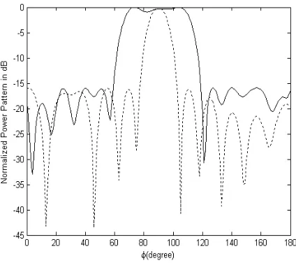
The design specifications of the reconfigurable array are shown in Table 3. There is a good agreement between desired and obtained results. However, the obtained value of the ripple (absolute value) for the flat-top beam in the region
0
0 110
70 ≤φ≤ is 0.93 db, slightly higher than the desired tolerance of 0.5 dB. Table 4 shows amplitude and phase distribution of the elements.
Radiation patterns using the optimized data are plotted in Fig.4.
Table 3 Desired and obtained results for reconfigurable array of dipole antennas
Pencil/Flat-top pair
Pencil Flat-top
Design Parameters
Desired Obtained Desired Obtained
Side Lobe
Level in dB -16.00 -15.95 -16.00 -15.91
Ripple in dB
NA NA 0.50 0.93
HPBW
Fig.4 Normalized absolute power patterns in dB for dual-beam array of dipole antennas
Table 4 Amplitude and phase distributions for reconfigurable array of dipole antennas
Parameters Voltage Amplitude and phase distribution for the dual beam array
0.28027 0.3366 0.67121 0.47772 0.62667 0.96395 0.79085 0.70471
0.25461 0.42746 0.47119 0.19759 0.21697 0.043398 0.24058 0.5199
Amplitude
0.86446 0.79726 0.57883 0.44313 0.43029 0.016636 0.21003 0.30501
43.816 -43.214 -65.3 -117.52 121.33 63.133 80.377 102.79
135.46 -31.982 -28.379 40.061 5.598 -35.233 -141.21 110.78
Phase in degree
127.13 130.19 102.18 35.672 24.502 73.98 93.107 92.898
VII. CONCLUSIONS
Two examples have been presented for the design of reconfigurable dual beams in vertical and horizontal plane. The first example analyzes the uniform circular array of isotropic elements while the second example deals with the uniform circular array of mutually coupled dipole elements. Patterns are generated using induced EMF technique in the second case. Proposed optimization technique is proved very effective for reconfiguration of the beams sharing a common set of excitation amplitude distribution. It makes the design circuit less expensive.
VIII. REFERENCES
[1]. O. M. Bucci, G. Mazzarella, and G. Panariello, “Reconfigurable arrays by phase-only control”, IEEE Trans. Antennas Propagat., vol. 39, no. 7, pp. 919–925, 1991. [2]. M. Durr, A. Trastoy, and F. Ares, "Multiple-pattern linear
antenna arrays with single prefixed amplitude distributions: modified Woodward-Lawson synthesis", Electron. Lett. vol. 36, no. 16, pp. 1345 - 1346, 2000.
[3]. Diaz, X., J. A. Rodriguez, F. Ares, and E. Moreno, “Design of phase-differentiated multiple-pattern antenna arrays", Microwave and Opt. Technol. Lett., Vol. 26, 52-53, 2000.
[4]. D. Gies and Y. Rahmat-Samii, “Particle swarm optimization for reconfigurable phase-differentiated array design”, Microw. Opt. Technol. Lett., vol. 38, pp. 168–175, 2003. [5]. Mahanti, G. K., A. Chakraborty and S. Das, "Design of
phase-differentiated reconfigurable array antennas with minimum dynamic range ratio", IEEE Antennas and Wireless Propagation Letters, Vol. 5, 262-264, 2006.
[6]. A. Chatterjee, G. K. Mahanti and P. R. S. Mahapatra,"Design Of Fully Digital Controlled Reconfigurable Dual-Beam Concentric Ring Array Antenna Using Gravitational Search Algorithm", Progress In Electromagnetics Research C, Vol. 18, 59-72, 2011
[7]. M. Panduro, A. L. Mendez, R. Dominguez, and G. Romero, “Design of non-uniform circular antenna arrays for side lobe reduction using the method of genetic algorithms”, Int. J. Electron. Commun., vol. (AEU) 60, pp. 713–717, 2006. [8]. M. Shihab, Y. Najjar, N. Dib, and M. Khodier, “Design of
non-uniform circular antenna arrays using particle swarm optimization”, J. Elect. Eng., vol. 59, no. 4, pp. 216–220, 2008.
[10]. D. Karaboga, B. Basturk, “Artificial Bee Colony (ABC) Optimization Algorithm for Solving Constrained Optimization Problems”, LNCS: Advances in Soft Computing: Foundations of Fuzzy Logic and Soft Computing, Vol. 4529, pp: 789-798, Springer-Verlag, 2007. [11]. D. Karaboga, B. Basturk, “A Powerful And Efficient
Algorithm For Numerical Function Optimization: Artificial Bee Colony (ABC) Algorithm”, Journal of Global Optimization, Vol. 39, Issue. 3, pp. 459-471, Springer, 2007.
[12]. Baykasoglu A, Ozbakir L, Tapkan P, “Artificial bee colony algorithm and its application to generalized assignment problem”, In: Swarm intelligence focus on ant and particle
swarm optimization. I-Tech Education and Publishing, Vienna, Austria, pp 113–144, 2007.
[13]. R. S. Elliott. 2003. Antenna Theory and Design. New York: IEEE/Wiley Interscience
[14]. M. Khodier and M. Al-Aqeel, ''Linear And Circular Array Optimization: A Study Using Particle Swarm Intelligence'', Progress In Electromagnetics Research B, Vol. 15, 347-373, 2009.