Available online: https://edupediapublications.org/journals/index.php/IJR/ P a g e | 2266
Automatic Integrated Technique for Road Detection & Tracking
Abstract
Implementation of unmanned aerial vehicle (UAV)
has recreated the detection, navigation and tracking
of respective region in novel way to get accuracy and
reliability in reliable way. UAV navigation, traffic
monitoring, and ground–vehicle tracking attain
attention due to their requirement in daily needs and
usage of the UAV videos has made task easy
especially in construction of roads and its associated
works even in remote areas. In this paper based on
two important algorithms is proposed for detection of
exact region for extraction and this is done by
graph-cut–based detection approach in initial stage while
road tracking in automatic way is done by fast
homography-based road-tracking scheme. Efficiency
and performance of the proposed work is attributed to
two aspects: the road detection is performed only
when it is necessary and most work in locating the
road is rapidly done via very fast homography-based
tracking. Finally experimental results attain
promising results over traditional state of art
methods.
Keywords: unmanned aerial vehicle (UAV), graph-cut–based detection, fast homography, road tracking
1. INTRODUCTION
Image processing is processing of images using
mathematical operations by using any form of signal
processing for which the input is an image, a series of
images, or a video such as a photograph or video
frame; the output of images processing may be either
an image or parameters related to the image. UAVs
may be employed for a wide range of transportation
operations and planning applications; traffic monitor,
transportation, measurement of typical roadway
usage, monitor parking lot utilization. UAV for
surveillance is an active research topic in computer
vision that tries to detect, recognize and track objects
over a sequence of images and it also makes an
attempt to the understand. Generally UAVs is used to
follow roads, rivers, oil gas pipeline inspection, and
the traffic parameter measurements. UAVs equipped
with cameras are viewed as a kind of low cost
platform that can provide efficient data for intelligent
transport systems. With the increasing use of vehicles
and their demands on traffic management, this kind
of platform becomes more and more popular.
Knowledge of road areas can provide users the
regions of interest for further navigation, detection
and data collection.
Dr.S.A.Mohammad
Gazni
Principal,Ph.D(Dept. of Physics) Osmania College,kurnool-518001,India.Fasiha Shereen
M.Tech.(Dept. of ECE) G.Pullaiah College of Engineering and technology,Kurnool.
Juveria Bughra
Btech (Dept. of ECE) G.Pullaiah College ofEngg and Technology,Kurnool.
Hunera Tarannum
M.tech. (Dept. of ECE) Ravindra college of
Available online: https://edupediapublications.org/journals/index.php/IJR/ P a g e | 2267 Automatic detection, tracking, and counting of a
variable number of objects are crucial tasks for a
wide range of applications such as security,
surveillance, management of access points, urban
planning, traffic control, etc. Road detection and
tracking, most approaches use the color (texture)
and/or structure (geometry)properties of roads.
Among them, the combination of road color and
boundary information have achieved more robust and
accurate results than using only one of them in road
detection, as shown in the work. To utilize Graph cut
algorithm for road detection and homography for
road tracking approach. In road detection, to utilize
the Graph cut algorithm because of its efficiency and
powerful segmentation performance in 2-D color
images. In road tracking, propose a fast road tracking
approach.
In comparison, UAV has advantages, including; there
is a low cost to monitor over long distances, it is
flexible for flying across broad spatial and temporal
scales, and it is capable of carrying various types of
sensors to collect abundant data. To collect
information for the transportation system, it is
important to know where the roads are in UAV
videos. Knowledge of road areas can provide users
the regions of interest for further navigation,
detection, tracking and data collection procedures.
Real time is required in many UAV based
applications; major target is how to effectively
combine both types of information for road detection
and tracking in an efficient way. Intuitively, there are
two rules to the making one integrated framework
efficient. First, each component of the framework
should be very fast and efficient. Second, if one
component is faster than the others in achieving the
same purpose, it would better make use of the fastest
component as much as possible. It should be noted
that these technique is not just limited to road
detection and tracking. It can be also applicable to
river, pipeline, or coastline detection and tracking in
UAV videos.
2. RELATED WORK
In the literature of road detection and tracking, most
approaches use the color (texture) and/or structure
(geometry) properties of roads. The combination of
road color and boundary information has achieved
more robust and accurate results than using only one
of them in road detection. Analyze the characteristics
of roads in color images of urban and campus
environments and algorithm is proposed to extract the
candidates of road boundaries and subsequently
combining the results of boundary detection with the
color information in the image captured, and then
present a method to precisely extract the road areas.
A popular approach to the problem of road detection
is the use of lane markings. Those markings are
localized to acquire boundary information that
facilitates the road detection process. Methods that
rely on lane markings are usually fast and simple,
using mainly grayscale images or videos. And second
popular method in road detection applications is the
use of color or brightness information to segment the
road, which is enhanced by some feature extraction
process such as edge detection to extract the road
boundaries. To improve road detection accuracy and
robustness to shadows, many researchers have
utilized more complex methods by processing
Available online: https://edupediapublications.org/journals/index.php/IJR/ P a g e | 2268 acquired from camera pairs. In road detection,
propose to utilize the Graph Cut algorithm because of
its efficiency and powerful segmentation
performance in 2-D color images. And in road
tracking, aim to track the road border structure
between two consecutive frames.
In a computer vision society, most developed
tracking techniques, such as particle filter, optical
flow ,mean shift are appearance-based methods.
Mean shift this paper presents a new approach to the
real-time tracking of non-rigid objects based on
visual features such as color and/or texture, whose
statistical distributions characterize the object of
interest. The proposed tracking is appropriate for a
large variety of objects with different color/texture
patterns, being robust to partial occlusions, clutter,
rotation in depth, and changes in camera position. It
is a natural application to motion analysis of the
mean shift procedure introduced earlier. The mean
shift iterations are employed the target candidate that
is the most similar to a given target model, with the
similarity being expressed by a metric based on the
Bhattacharyya coefficient. Road detection and
tracking in UAVs, particularly low- and mid-altitude
UAVs in this paper, which can be used for
autonomous navigation and traffic surveillance and
monitoring is done in accurate way. A monocular
color camera is often equipped in this area, the
camera can clearly capture each vehicle on the
ground and also has large spatial view on traffic
areas. The other research line in UAV-based road
detection uses satellite or high altitude UAVs which
aims to identify road network, including many
junctions and roundabouts from an image. In general,
region color distributions and/or boundary structures
are probably the important information utilized for
road detection. Road color distributions using
Gaussian mixture models (GMMs) from given
sample images, and then determine road pixels in
each frame by checking the probabilities of pixels
that fit the Gaussian mixture models.
3. PROPOSED METHOD
FAST ROAD DETECTION AND TRACKING IN
UAV VIDEOS
In this techniques we applied detection to the initially
segment road regions then we applied homography
transformations between two consecutive frames.We
applied homography transformation to project road
regions in previous frames onto the current frames
for tracking after that road areas are propagated by
using current frames and adaptive –GMM based road
detection.
A. Road Detection and Adaptive GMMs:
The road detection is nothing but to classify road
pixels from non-road pixels of a frame. We can easily
establish the probability that the each pixel belonging
to the road (road c ). By selecting the log-normal as
follows we are going for the application like image
segmentation.
P(road c) =log
= log (1)
Available online: https://edupediapublications.org/journals/index.php/IJR/ P a g e | 2269 = log - log
The above equations include GMM1 and GMM2.
These are nothing but GMMs of road and non-road
respectively.
As shown in equation 1 two GMMs are modeling
the road and non-road pixels are are required. For
each GMM k- components are designed. K is
typically set to 5. This is working very well in our
project. In all we require 2K components are
required.
To create 2K parts, the collected road/non-road
pixels to be partitioned off into K clusters. The
Orchard Bouman agglomeration rule is utilized
during this paper since it provides associate degree
optimum answer for clusters with Gaussian
distributions. The rule repeats a binary ripping
procedure that splits one knowledge cluster into 2
supported the Eigen value of the variance matrix till
the specified number of clusters is reached. Figure a
pair of illustrates the ripping procedure. Low
variance in every cluster is achieved, which benefits
the separation between road and non-road pixel.
Figure 1: Illustration of the Orchard-Bouman
clustering procedure in 2D data: the whole data set is
split into two (red and green) based on the center of
distribution (blue dot) and the estimated eigenvector
(blue line).
Algorithm 1: The creation of a GMM
Input: The number of components K and a set of
road (or non-road) pixels Ω.
Output: K components C1, ..., CK. 1. C m = Ω, m =
1. Cm is a cluster with the largest eigenvalue.
2. For (k = 2, ..., K)
2.1 For C m, calculate the mean value µm, the
covariance matrix Σ m, the largest eigenvalue λm and the corresponding eigenvector vm of Σm.
2.2 Split Cm into two sets, Ck = {c ∈ Cm: vmc ≤ v
mµm }, and Cm = Cm − Ck.
2.3 For (i = 1, ..., k)
2.3.1 For Ci, calculate the covariance matrix Σi,
the largest eigenvalue λi of Σi.
2.3.2 If (λi > λm), m = i.
An UAV video perpetually spans an outsized
distance, where road and non-road pixels could
amendment greatly attributable to shadows and
varying constructions. A static GMM trained by the
Available online: https://edupediapublications.org/journals/index.php/IJR/ P a g e | 2270 seem to be powerful enough to explain road/non-road
pixels with dynamic changes.
So we tend to update GMMs at intervals primarily
based on obtained results. An easy thanks to update
the GMMs is to rerun the tactic in algorithmic
program I, that but is slow.
We adopt the mathematician mixture clump
algorithmic program for acceleration. It clusters new
pixels into K teams supported existing GMM
elements that have the most important probability
value manufacturing the pixels. New GMMs area
unit outlined by these clustered picture element
colors. This theme is delineated in Algorithm a pair
of.
We have a tendency to decision GMMs with and
while not this change procedure as adjustive and
static GMMs, severally. Note that adjustive GMMs
projected in area unit completely different. They are
designed for modeling background adjustive to
lighting and long-term scene changes, however just
for videos captured by fixed cameras.
Algorithm 2: The procedure of updating a GMM
Input: A set of new road (or non-road) pixels Ωn,
and GMM components C1o, ..., CKo : (µi, Σi), i = 1,
..., K.
Output: New GMM components C1n, ..., CKn.
1. Cn 1 = ... = CKn = NULL.
2. l max = −1, lmax records the largest likelihood
value.
3. For each pixel ci in Ωn
3.1 l max = −1.
3.2 For (j = 1, ..., K)
3.2.1 Calculate the likelihood value l ji of the
component Cjo producing the pixel ci: l ji = 1 √det
(Σ j ) 12 [(ci − µj) TΣ −j 1(ci − µj)]
3.2.2 If (lji > lmax), lmax = lji and m = j.
3.3 Cn m = Cmn ∪ {ci}
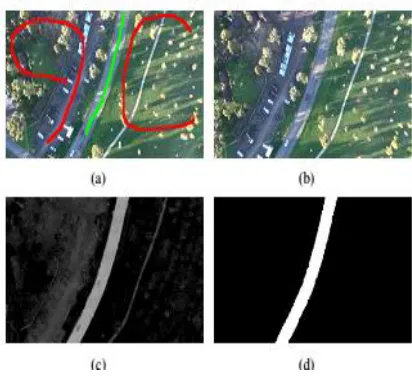
Figure 2 gives an illustration of the road detection
process.
Figure 2(a) shows red and green stokes, which
denote road and non-road pixels, respectively. There
are 10 images scratched to provide those road and
non-road pixels.
Figure 2(b) is a testing frame.
Using Eq. (1), a map representing probabilities of
pixels belonging to road is obtained in Figure 2(c).
We then binarize the map. The binarization
threshold can be given empirically (A typical value is
90, when the map is scaled to 0-255) or determined
automatically using the Otsu algorithm to minimize
within group variances. Morphology operations
including erosion and dilation are performed to
remove noises and fill holes. Contour analysis is
applied to find large connected regions, which are the
Available online: https://edupediapublications.org/journals/index.php/IJR/ P a g e | 2271 B. Fast Homography Estimation:
In this step, we can easily estimate the homograph
transformation between 2 consecutive frames.
Homography transformation may be a geometrical
transformation between 2 planes, defined by a 3×3
matrix.
All second plane-based transformations can be
outlined by this homography matrix. It’s eight
degrees of freedom: three for the rotation, three for
the interpretation and a pair of for the normal vector
to the plane.
Thus, to calculate a homography transformation
between 2 pictures, we want a minimum of four pairs
of matched points.
The traditional thanks to estimate the homography
transformation between 2 pictures is:
(1) Feature detection,
(2) Feature matching between 2 frames, and
(3) Homography estimation supported these matched
options. Feature matching may be a terribly long
step.
Figure 2: Road detection. (a): stoke examples for
collecting road (green) and non-road (red) pixels. (b)
A test frame; (c): the probability map of pixels
belonging to road for (b). (d) the road segmentation
result for (b).
Apply feature selection techniques to exchange the
step (2), which is effective and economical.
The options with success tracked square measure
treated because the matched options between 2
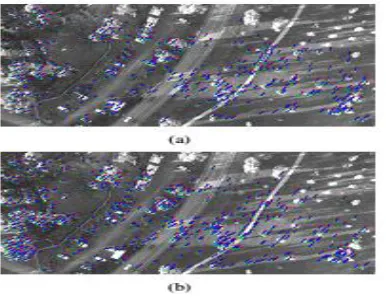
consecutive frames in videos. Figure 3 Provides AN
illustration of feature pairs obtained by matching and
selection techniques, where purpose movements in
Figure 3(a) square measure similar with purpose
Available online: https://edupediapublications.org/journals/index.php/IJR/ P a g e | 2272
Figure 3 Feature pairs marked by green points
(detected in the previous frame), red points (tracked in
the current frame) and connected by blue lines, where
variations between two set points in (a) are similar in
(b). (a) Successfully matched features; (b) successfully
tracked features.
In this work, quick options are chosen for
following because they have the most effective
balance between accuracy and efficient for our
purpose, compared with alternative well-known
features like SURF, SIFT and Harris . We find quick
options during a previous frame.
Then the Lucas-Kanade technique is applied to
trace these options in a current frame through
estimating optical flow, as the movement between 2
frames is sort of tiny. Finally, the feature pairs with
success caterpillar-tracked are used to estimate the
homography transformation. The random sample
accord (RANSAC) technique styles a study estimation
theme. It randomly selects four pairs for matrix
estimations, counts inlinear pairs that match a matrix
for every estimation, and chooses the matrix with the
largest range of inliers. After that, least-square fitting
is performed on the inliers to provide the final
transformation matrix.
C. Homography based Road Tracking:
With the homography transformation matrix H, a
detected road region within the previous frame will be
projected onto the present frame through remodeling
the road contours within the previous frame by
multiplying H. as a result of UAV movements, within
the current frame, there square measure new coming
back regions wherever road areas ought to be
extracted. We have a tendency to solve it by playing
the road detection formula delineates within the
section A.
As there square measure solely little new coming
back regions between 2 consecutive frames, the road
detection on them is sort of quick. We have a tendency
to obtain the new coming back regions within the
current frame by orientating the previous frame to the
present one. Once the road projection and detection,
we have a tendency to merge these 2 areas to provide
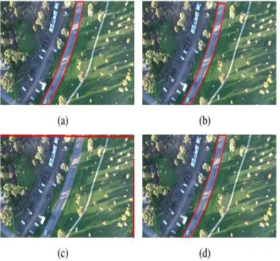
the ultimate segmentation result. Fig.5. shows some
Available online: https://edupediapublications.org/journals/index.php/IJR/ P a g e | 2273 Figure 4: Road tracking by homography alignment,
where the two frames (a) and (b) are not consecutive
in order to illustrate the clear gap. (a): Road detection
result; (b) and (c) road and image frame rectangle
alignment results by homography transformation; (d)
final road segmentation result.
4. RESULTS
Figure 5: Source image
Figure 6: Labelled image
Figure 7: Segmented image
Available online: https://edupediapublications.org/journals/index.php/IJR/ P a g e | 2274 Figure 9: Selected point for KLT tracking
Figure 10: Points obtained for new query image
Figure 11: Marked portions for the query image
Figure 12: Segmented before refinement
Figure 13: Final segmented
5. CONCLUSION
Road detection and tracking system on road images for
unmanned aerial vehicle videos in urban area is
proposed. In this paper, presented on graph cut for
road detection and homography for the road tracking
in the urban area. The objective is to effectively
combine both types of information for road detection
and tracking in urban area in an efficient way for
surveillance, transportation system. For many fields,
transportation, security surveillance, traffic monitoring
these system performance and accuracy plays an
important role. From the point of view of practical
application, it is necessary to consider the robustness
of road image based on graph cut algorithm and
Available online: https://edupediapublications.org/journals/index.php/IJR/ P a g e | 2275 existing system is that it gives less accuracy, time for
the road tracking.
REFERENCES
[1] B. Coifman, M. McCord, M. Mishalani, and K. Redmill, “Surface transportation surveillance from unmanned aerial vehicles,” in Proc. 83rd Annu. Meet. Transp. Res. Board, 2004, pp. 1–9.
[2] [Online]. Available:
http://www.list.ufl.edu/ATSS.htm
[3] [Online]. Available:
http://soliton.ae.gatech.edu/people/ejohnson/
[4] E. Frew et al., “Vision-based road-following using a small autonomous aircraft,” in Proc. IEEE Aerosp. Conf., Mar. 2004, vol. 5, pp. 3006–3015.
[5] H. Zhou, D. Creighton, L. Wei, D. Y. Gao, and S. Nahavandi, “Video driven traffic modeling,” in Proc. IEEE/ASME Int. Conf. Adv. Intell. Mechatronics, Jul. 2013, pp. 506–511.
[6] Y. He, H. Wang, and B. Zhang, “Color-based road detection in urban traffic scenes,” IEEE Trans. Intell. Transp. Syst., vol. 5, no. 4, pp. 309– 318, Dec. 2004.
[7] G. K. Siogkas and E. S. Dermatas, “Random-walker monocular road detection in adverse conditions using automated spatiotemporal seed selection,” IEEE Trans. Intell. Transp. Syst., vol. 14, no. 2, pp. 527–538, Jun. 2013.
[8] Y. Boykov, O. Veksler, and R. Zabih, “Fast approximate energy minimization via graph cuts,” IEEE Trans. Pattern Anal. Mach. Intell., vol. 23, no. 11, pp. 1222–1239, Nov. 2001.
[9] D. Comaniciu, V. Ramesh, and P. Meer, “Real-time tracking of non-rigid objects using mean shift,” in Proc. IEEE Comput. Vis. Pattern Recog., 2000, pp. 142–149.