Mono-Static Scattering from Array Antennas
with Arbitrary Loadings
Ming Jin*, Yang Bai, and Hong-Cheng Yin
Abstract—Scattering from array antennas is a complicated problem, containing the structural and mode items in nature. The complexities in analyzing the latter one also come from the feeding network that follows antenna unit ports, where active or anisotropy devices may exist. Therefore, it is significant that an efficient method can be constructed to analyze array antenna scattering with arbitrary port reflections. In this work, we address this problem by adopting the S-matrix model for the antenna array, aiming to efficiently and accurately compose the mode scattering in case of arbitrary reflections at feeding ports. In the numerical process, the antenna reciprocity is utilized in obtainning the basis for the scattering composition analysis. In case of various loading conditions numerical results are presented, showing that the composed scattering results by theS-matrix model agree well with that obtained by direct full scale simulations. Then the methods for obtaining radiation and scattering results of a large antenna array based on those of small arrays, are reviewed and extended for composing the large antenna array scattering in case of variable loading conditions. And, promising results are obtained.
1. INTRODUCTION
The antennas have been found to be one of the major scattering sources on kinds of vehicles. Therefore, it is significant to analyze the scattering characteristics of antennas for detection or stealth purposes. Different from general scatters which generate only the structure scattering, an antenna would receive the illuminating energy, reflect it at the port, and finally reradiate, generating the so-called mode scattering [1–7]. As a result, the analysis on the scattering from an antenna is two folds, for the structure scattering and the mode scattering.
The scattering from antennas have been studied theoretically and experimentally [1–4]. The structural and mode scattering from a single antenna can be separated by the open-short loading method in the scattering computation or measurement configuration. The bi-static mode scattering is found to be with the same pattern as the antenna radiation. When it comes to an antenna array, which is more practical nowadays, the comprehensive scattering analysis is still challenging. The differences in scattering and radiation from different antenna units exist, while mutual coupling between units brings more difficulties [7–9]. As a result the analysis on the mode scattering of an antenna array is much more complicated than that of a single antenna, and the open-short loading method for separating the mode scattering becomes difficult in implementation. On the other hand, when it comes to a large array, huge computation loads for the full-scale modeling will be encountered. For that problem, efficient methods were proposed to obtain the scattering and radiation of the large array based on results of small arrays [8, 10, 11]. However, those works were done when each antenna unit is under the same loading condition.
Received 6 August 2014, Accepted 1 September 2014, Scheduled 5 September 2014 * Corresponding author: Ming Jin ([email protected]).
On the other hand, the complexities of antenna array scattering also come from the feeding network that follows the feeding ports and impacts the mode scattering [5, 6]. In fact, it is still difficult numerically to model the antenna layer and the feeding network layer together, as active or anisotropy devices may exist in the latter one. Therefore, it is significant that an efficient method can be constructed to obtain the array antenna scattering under arbitrary port loading (or reflections) conditions. Then effects on the mode scattering by the feeding network can be further evaluated by setting proper reflection coefficient at each feeding port, as the antenna layer is a linear device in most cases.
In this work, we address this need by adopting the scattering parameter matrix (S-matrix) model proposed by Wiesbeck and Heidrich [1] for the characteristic evaluation of a multi-port antenna, to analyze the scattering of array antennas with arbitrary port loadings. In this paper, other than only separating or recognizing the mode scattering from an array antenna in the numerical study, we are trying to correctly compose the mode scattering according to a certain loading condition. Based on the nature of antenna scattering, the structure scattering, antenna radiation, antenna receiving signals, port mutual coupling are obtained separately to fulfill the task. Then in case of a varied loading condition, repeating full-scale numerical simulations for scattering results can be avoided. The antenna reciprocity is utilized in the process, replacing the open-short loading method in obtaining the basis for the scattering composition analysis. For verification purpose, we compared the composed mode scattering by the S-matrix model with the directly simulated results, when the array units are with various loadings. We also extended the methods in [8, 10] to obtain the scattering from large array based on results of small arrays, however as should be highlighted, with various loading at each feeding port.
2. S-MATRIX MODEL FOR SCATTERING FROM ANTENNA ARRAY 2.1. S-Matrix Model
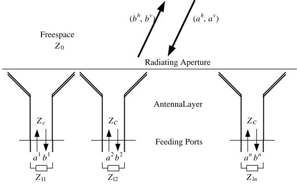
The configuration of mono-scattering from an array antenna is presented in Figure 1, where each unit is fed through a single mode transmission line with the characteristic impedanceZc. The bh,bv stand for the outward fields from the array antenna (in the far-field region, with the factor exp(−jkr)/r compensated), the ah, av stand for the illuminating plane-waves. In the mono-static case, bh, bv and
ah,av share the same direction (θ,ϕ). Theb1. . . bnare the outward signals (voltage) while thea1. . . an
are the inward signals at feeding ports.
According to Wiesbeck’s work [1], an S-parameter matrix can be used to fully describe the
Z
Zl1
Feeding Ports Radiating Aperture
Z
Zl2
Freespace
Z0
(ah, av) (bh, bv)
AntennaLayer
Z
Zln
a1 b1 a2 b2 an bn
c c c
characteristics of a multi-port antenna, and consequently, an antenna array: ⎛ ⎜ ⎜ ⎜ ⎜ ⎜ ⎜ ⎜ ⎜ ⎝ bh bv b1 b2 .. . bn ⎞ ⎟ ⎟ ⎟ ⎟ ⎟ ⎟ ⎟ ⎟ ⎠ = ⎛ ⎜ ⎜ ⎜ ⎜ ⎜ ⎜ ⎜ ⎜ ⎜ ⎝
Shh Shv Sh1 Sh2 · · · Shn Svh Svv Sv1 Sv2 · · · Svn S1h S1v S11 S12 · · · S1n S2h S2v S21 S22 · · · S2n
..
. ... ... ... . .. ...
Snh Snv Sn1 Sn2 · · · Snn
⎞ ⎟ ⎟ ⎟ ⎟ ⎟ ⎟ ⎟ ⎟ ⎟ ⎠ · ⎛ ⎜ ⎜ ⎜ ⎜ ⎜ ⎜ ⎜ ⎜ ⎝ ah av a1 a2 .. . an ⎞ ⎟ ⎟ ⎟ ⎟ ⎟ ⎟ ⎟ ⎟ ⎠ (1)
It can be summarized as:
bhv 21
[bpo]n1
= S 1 22 S 2 2n S3
n2 S 4
nn
· ahv
21
[apo]n1
(2)
where: [S1] defines the structure scattering; [S2] defines the radiation of antenna units because of an unit excitation at each feeding port while the other ports are match loaded; [S3] describes the receiving process of antenna units due to the plane wave illumination; [S4] defines the reflection and mutual-coupling between feeding ports, to the antenna side. At last, it should be noted that the elements in [S1], [S2], [S3] vary with the mono-static direction (θ,ϕ), while those in [S4] don’t.
On the other hand, the reflections at the feeding ports, to the load side, can be written as:
[apo]n1= [Γ]nn· [bpo]n1 (3)
The matrix [Γ] defines the reflection at each feeding port. If each feeding port was loaded with impedanceZli as in Figure 1, then [Γ] is a diagonal matrix with:
Γii= (Zli−Zc)/(Zli+Zc) (4)
wherei= 1. . . n.
If each feeding port was connected to a feeding network, then [Γ] is no longer a diagonal one. Considering the scattering process, and combine Eq. (3) with the following equation that obtains the outward signal at feeding ports:
[bpo]n1= S3n2·
ahv
21+ S 4
nn[apo]n1 (5)
We will have:
bhv
21= S 1
22·
ahv 21+ S
2 2n·
[I]nn−[Γ]nn S4nn−1[Γ]nn S3n2·
ahv
21 (6)
This equation demonstrates the scattering from the array antenna. The first item on the right side is the structure scattering from the antenna array, while the second item is the mode scattering. Agreeing to the established concept [1, 4], the structure scattering is the scattering when no reflections at feeding ports exist, while the mode scattering is that directly related to the loading conditions at feeding points, which can be modeled by [Γ].
bhv
21= S 1
22+
Smod([Γ]) 22
·ahv
21= S
tot([Γ]) 22·
ahv
21 (7)
When [Γ] = [0], [Smod([Γ])]22= [0]22 and [Stot([Γ])]22= [S1]22.
And consequently, the total RCS can be:
√
σhh √σhv √
σvh √σvv
2.2. Computation Process in Numerical Studies
It is much more difficult to use the open-short method to separate the basis for mode scattering composition of array antennas, than that of a single antenna. On the other hand, Eqs. (2) and (6) clearly demonstrate the four necessary parts (sub-matrixes) for the antenna scattering composition. It is important to obtain those bases by numerical or experimental methods for the comprehensive scattering analysis of an array antenna. Then, no full-wave and full-scale simulation has to be performed to get the scattering in case of a varied loading condition, as by using Eq. (6) one is able to obtain the results with an equaling accuracy but a much higher efficiency.
In nature, each of the sub-matrixes defines an unique physical process, while some of them can be included in a certain computation model:
(a) In the scattering configuration, where plane wave is illuminating the antenna array each feeding port of which is match loaded, the [S1] (structural scattering) and [S3] (receiving signal at each port) can be recorded.
(b) In the radiation model, where each feeding port is excited one by one while the other ports are match loaded, it is possible to record the [S2] (radiation) and [S4] (port reflection and mutual coupling).
Additionally, according to the reciprocity of each antenna unit, there lies the relationship between [S2] and [S3]:
S3
j,i= S2
i,j(−jλZc)/Z0 (9)
It means that one can obtain either of [S2] or [S3] based on results of the other. For example, in preparing the results of S-matrix in this work, we obtained the [S1], [S3] and [S2] (got by Eq. (9)) in the scattering computation model, and computed the [S4] in the S-parameter computation between each port.
It is clear that by implementing scattering (ports matched) and radiation simulations, one can obtain the complete basis for composing the array antenna scattering. Also by using Eq. (9), one is able to optimize the computation process, or to obtain [S3] in case of that numerical tools at hand cannot
provide the required results.
3. NUMERICAL EXAMPLES 3.1. Configuration
A linear array with 7 waveguide radiators is considered here, as shown in Figure 2. For reference, all the geometric parameters of each antenna unit are listed in Table 1. To compute the scattering, an MLFMA based commercial software (FEKO) was used [12]. In the numerical study, each unit was fed by an exciting pin followed by an ideal feeding transmission line with 50 Ω characteristic impedance.
pl fl
wl
wa
wb h
l
a hb
Figure 2. Geometry of 7 elements waveguide antenna array.
Table 1. Geometric parameters of each antenna unit (see Figure 2).
Paras: wa wb wl pl fl a hb hl
-90 -80 -70 -60 -50 -40 -30 -20 -10 0 10 20 30 40 50 60 70 80 90 theta(deg)
Recived Signal at each Port due to unit plane-wave illumiation
Unit 1 Unit 2 Unit 3 Unit 4
-20 -15 -10 -5 0 5 10 15 20
dBm
Figure 3. Calculated receiving pattern of each antenna unit.
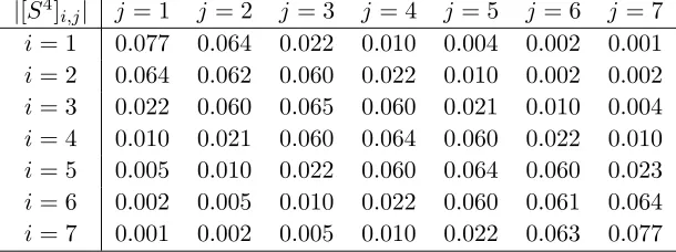
Table 2. Calculated port reflection and mutual coupling coefficients.
|[S4]i,j| j= 1 j= 2 j = 3 j= 4 j= 5 j= 6 j= 7
i= 1 0.077 0.064 0.022 0.010 0.004 0.002 0.001
i= 2 0.064 0.062 0.060 0.022 0.010 0.002 0.002
i= 3 0.022 0.060 0.065 0.060 0.021 0.010 0.004
i= 4 0.010 0.021 0.060 0.064 0.060 0.022 0.010
i= 5 0.005 0.010 0.022 0.060 0.064 0.060 0.023
i= 6 0.002 0.005 0.010 0.022 0.060 0.061 0.064
i= 7 0.001 0.002 0.005 0.010 0.022 0.063 0.077
At the end of each feeding line, cases of variable impedance are considered. In this paper, we are to directly compose the mode scattering from array antennas with various loading conditions.
The incident plane-waves are in the XOZ plane (ϕ = 0◦) with V polarization, which is also the dominating radiating polarization of each antenna unit. Considering only the co-polar scattering, the Eq. (6) can be simplified into:
bv =S1vv·av+ S2vn1n·[I]nn−[Γ]nn S4nn−1[Γ]nn S3nvn1·av (10)
3.2. Mode Scattering under Arbitrary Loading Condition
We follow the computation process described in Section 2.2 in founding theS-matrix elements at cared mono-static directions (θ = −90◦∼90◦, ϕ = 0◦), then the Eq. (10) can be used to compose the co-polar mono-scattering in case of arbitrary loadings. In Figure 3, the received signals at each port of the antenna array versus plane-wave illuminations from different directions are plotted, which were obtained in the scattering computations (port matched). The differences in the receiving signal results at each port can be clearly observed. Those receiving signal results ([S3]) are used to obtain the active element radiation results ([S2]) by using Eq. (9). In Table 2, the calculated port reflection and mutual coupling coefficients ([S4]) are presented, which are obtained in the radiation/S-parameter computation. Clearly the computed [S4] is a diagonal dominating one, as in nature the mutual coupling decreases as the distance between antenna units increases.
Since the necessary elements in [S2], [S3], and [S4] are obtained, the mode scattering from this
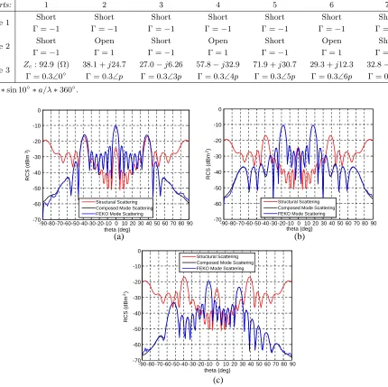
Table 3. Three loading conditions at each feeding port.
Ports: 1 2 3 4 5 6 7
Case 1 Short Γ =−1
Short Γ =−1
Short Γ =−1
Short Γ =−1
Short Γ =−1
Short Γ =−1
Short Γ =−1
Case 2 Short Γ =−1
Open Γ = 1
Short Γ =−1
Open Γ = 1
Short Γ =−1
Open Γ = 1
Short Γ =−1
Case 3 Zc: 92.9 (Ω) Γ = 0.3∠0◦
38.1 +j24.7 Γ = 0.3∠p
27.0−j6.26 Γ = 0.3∠3p
57.8−j32.9 Γ = 0.3∠4p
71.9 +j30.7 Γ = 0.3∠5p
29.3 +j12.3 Γ = 0.3∠6p
32.8−j18.9 Γ = 0.3∠7p p= 2∗sin 10◦∗a/λ∗360◦.
-90-80-70-60-50-40-30-20-10 0 10 20 30 40 50 60 70 80 90 theta (deg)
Structural Scattering Composed Mode Scattering FEKO Mode Scattering
-90-80-70-60-50-40-30-20-10 0 10 20 30 40 50 60 70 80 90 theta (deg)
Structural Scattering Composed Mode Scattering FEKO Mode Scattering
-90-80-70-60-50-40-30-20-10 0 10 20 30 40 50 60 70 80 90 theta (deg)
Structural Scattering Composed Mode Scattering FEKO Mode Scattering -70
-60 -50 -40 -30 -20 -10 0
RCS (dBm )
2
-70 -60 -50 -40 -30 -20 -10 0
RCS (dBm )
2
-70 -60 -50 -40 -30 -20 -10 0
RCS (dBm )
2
(a) (b)
(c)
Figure 4. Comparison of mode scattering results (σV V,θ=−90◦∼90◦,ϕ= 0◦) under different loading conditions at 10 GHz. (a) Case 1. (b) Case 2. (c) Case 3. The loading conditions are listed in Table 3.
loading condition). It is clear the composed mode scattering results agree very well with the directly simulated ones, and the mode scattering characteristics caused by the loading conditions are clearly presented. It is proven that without performing repeating full scale simulations, one can use the S -Matrix model to compose the scattering under arbitrary loading conditions with promising accuracy.
4. EXTENSION TO LARGE ARRAY
a small periodic linear antenna array can be used to obtain those from a large array, by the hybrid AEP (Active Element Pattern) [8] and IIEPM (Improved Induced Element Pattern) [10, 11] method respectively. It should be noted that, each antenna unit was with the same loading condition in those works. Additionally, by approximately mapping the mutual coupling results ([S4]) of a small array onto
that of a large array, one is able to fully analyze the mode scattering from large array under arbitrary loading conditions, based on results of small arrays.
4.1. Extension Approach
To be specific, the IIEPM method can be used to obtain the structural scattering of a large array (each port was match loaded), which is [S1]. For example, if the 7 element array considered is large enough that the central element scattering is no longer affected by the array edge, then with scattering results of an 8 element array, one can obtain the scattering of an any larger array. Detailed formulations can be found in [10].
On the other hand, the well-established hybrid AEP method can be used to obtain the radiation of a large array based on that of a small array. The key idea of the hybrid AEP method is the separate mapping of radiation ([S2]) from central elements and edge elements [8]. Assuming antenna reciprocity, the unit receiving patterns ([S3]) of a large array can be obtained similarly. For the need of mode scattering composition in case of arbitrary loadings, the [S4] of a large array is also required to be known. Using the same mapping strategy of the hybrid AEP method, this is achievable. A demonstrating figure that illustrates the mapping procedure of those sub - matrixes ([S2], [S3], [S4]) is presented in Figure 5. The difference between the mapping of [S2]([S3]) and [S4] is that, in the latter one there is no need to compensate the phase caused by projected unit position changes.
4.2. Numerical Results
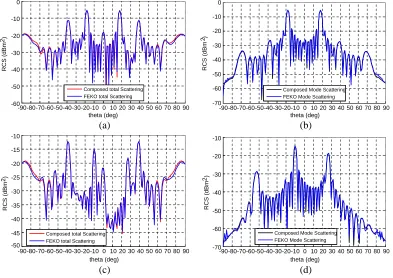
The scattering from a 12-element array is considered, which is still in reach of FEKO for full scale computations. Once again, direct simulations were performed for reference results. The S-matrix for this array is obtained based on that of the 7 element array and 8 element array (for structural scattering by IIEPM). The composed scattering in the loading case 2 and 3 (see Table 3) were compared with those by direct simulations, in Figure 6. Good agreements in results by two methods can be observed, and clearly the difference (total scattering) in largeθdirections should be blamed to the structure scattering. Using results of larger arraies (9 and 10 elements) for the IIEPM method will help in this case. It can also be observed that the relationship between the mode and structural scattering is correctly handled by the S-matrix model, as the total scattering results by S-matrix composition and direct simulation agreed with each other. As can be concluded, by addtionally mapping the mutual coupling results for the large antenna array, the combination of S-matrix model and the hybrid AEP along with IIEPM methods yielded promissing scattering results, under various loading conditions.
To further demonstrate the efficiency and accuracy of the extendedS-matrix composition method, another set of results for a even larger array with 60 elements are presented and compared in Figure 7.
1 2 3 4 5 6 7 8 9 10 1112
1 2 3 4 5 6 7
1 2 3 4 5 6 7
1 2 3 4 5 6 7
1 2 3 4 5 6 7 8 910 1112
Small Array
Large Array
[ S2]
[ S2] [ S3]
[ S4] [ S
4 ] [ S3]
1 2 3 4 5 6 7 8 9
10 11 12
-90-80-70-60-50-40-30-20-10 0 10 20 30 40 50 60 70 80 90 theta (deg)
Composed total Scattering FEKO total Scattering
-90-80-70-60-50-40-30-20-10 0 10 20 30 40 50 60 70 80 90 theta (deg)
Composed Mode Scattering FEKO Mode Scattering
-90-80-70-60-50-40-30-20-10 0 10 20 30 40 50 60 70 80 90 theta (deg)
Composed total Scattering FEKO total Scattering
-90-80-70-60-50-40-30-20-10 0 10 20 30 40 50 60 70 80 90 theta (deg)
Composed Mode Scattering FEKO Mode Scattering -60
-50 -40 -30 -20 -10 0
RCS (dBm )
2
-70 -60 -50 -40 -30 -20 -10 0
RCS (dBm )
2
-50 -45 -40 -35 -30 -25 -20 -15 -10
RCS (dBm )
2
-70 -60 -50 -40 -30 -20 -10
RCS (dBm )
2
(a) (b)
(c) (d)
Figure 6. Comparison of scattering results (σV V, θ = −90◦∼90◦, ϕ = 0◦) of a 12 elements array under different loading conditions at 10 GHz. (a) Total scattering Case 2. (b) Mode scattering Case 2. (c) Total scattering Case 3. (d) Mode scattering Case 3. The loading conditions are listed in Table 3.
-60 -50 -40 -30 -20 -10 0 10 20 30 40 50 60
theta(deg)
Composed total Scattering FEKO total Scattering
-60 -50 -40 -30 -20 -10 0 10 20 30 40 50 60
theta(deg)
Composed total Scattering FEKO total Scattering
-50 -45 -40 -35 -30 -25 -20 -15 -10 -5 0 5 10
RCS (dBm )
2
-50 -45 -40 -35 -30 -25 -20 -15 -10 -5 0 5 10
RCS (dBm )
2
(a) (b)
Figure 7. Comparison of scattering results (σV V,θ=−60◦∼60◦,ϕ= 0◦) of a 60 elements array under different loading conditions at 10 GHz. (a) Total scattering Case 2. (b) Total scattering Case 3. The loading conditions are listed in Table 3. (Composed results: 0.2◦ angular interval; FEKO results: 0.5◦ angular interval).
For a clear view, the figures are enlarged while the θ region was zoomed to (−60◦. . .60◦). The computations for the S-matrix extension approach cost less than 3 hour to obtain all the required
5. CONCLUSION
In this work, we report the attempt in composing the scattering from array antennas with arbitrary loadings. The S-matrix model was adopted to address this problem, and the structure scattering, antenna radiation, antenna receiving signals, port mutual coupling are obtained separately to fulfill the task. The computation process is discussed, and the antenna reciprocity is utilized in obtaining the basis for composing the mode scattering. The scattering results by the direct simulation and the S-matrix composition agree well with each other, for a linear array antenna with various port loadings. For the efficient scattering analysis of large array antenna, extension to the existing hybrid AEP and IIEPM methods based on the results of small arrays, was made by additionally mapping the mutual coupling results. Then the basis for extendedS-matrix composition model was completed, and promising results were obtained in case of various loading conditions. Although this work was performed based on the adoption and extension of existing model and methods, it demonstrated the idea of composing the total scattering from array antennas for comprehensive analysis purpose. Also, the presented computation process offers guidance and reference for practical applications on antenna scattering properties.
REFERENCES
1. Wiesbeck, W. and E. Heidrich, “Wide-band multiport antenna characterization by polarimetric rcs measurements,” IEEE Trans. on Antennas Propagat., Vol. 46, No. 3, 341–350, 1998.
2. Shrestha, S., M. D. Balachandran, M. Agarwal, L. Zou, and K. Varahramyan, “A method to measure radar cross section parameters of antennas,”IEEE Trans. on Antennas Propagat., Vol. 56, No. 11, 3494–3500, 2008.
3. Hu, S., H. Chen, C. Law, Z. Shen, L. Zhu, W. Zhang, and W. Dou, “Backscattering cross section of ultrawideband antennas,” IEEE Antennas Wireless Propagation Lett., Vol. 6, 70–73, 2007. 4. Liu, Y., S. Gong, and D. Fu, “Theoretic study of antenna scattering,” ACTA Electronica Sinica,
Vol. 33, No. 9, 1611–1613, 2005 (in Chinese).
5. Jehn, D. and S. Lee, “Inband scattering from arrays with series feed networks,” IEEE Trans. on
Antennas Propagat., Vol. 43, No. 8, 867–873, 1995.
6. Jehn, D. and V. Flokas, “In band scattering from arrays with parallel feed networks,”IEEE Trans.
on Antennas Propagat., Vol. 44, No. 2, 172–178, 1996.
7. Zhang, S., S. Gong, Y. Guan, and Q. Gong, “Synthesis of array radiation and scattering patterns including mutual coupling,” Chinese Journal of Computational Physics, Vol. 28, No. 3, 420–426, 2011 (in Chinese).
8. Kelly, D. and W. Stutzman, “Array antenna pattern modeling methods that include mutual coupling effects,” IEEE Trans. on Antennas Propagat., Vol. 41, No. 12, 1625–1632, 1993.
9. Maaskant, R., M. Ivashina, O. Iupikov, E. Redkina, S. Kasturi, and D. Schaubert, “Analysis of large microstrip-fed tapered slot antenna arrays by combining electrodynamic and quasi-static field models,” IEEE Trans. on Antennas Propagat., Vol. 59, No. 6, 1798–1807, 2011.
10. Zhang, S., S. Gong, Q. Gong, Y. Guan, and B. Lu, “Application of the active element pattern method for calculation of the scattering pattern of large finite array,” IEEE Antennas Wireless
Propagation Lett., Vol. 10, 83–86, 2011.
11. Zhang, S., S. Gong, and Y. Liu, “Fast method for calculating the scattering from large plane arrays,” ACTA Electronica Sinica, Vol. 41, No. 9, 1680–1684, 2013 (in Chinese).
![Figure 5. Demonstration of mapping of sub-matrixes [S2], [S3] and [S4].](https://thumb-us.123doks.com/thumbv2/123dok_us/1991011.1263430/7.612.182.437.575.713/figure-demonstration-mapping-sub-matrixes-s-s-s.webp)