Available online: https://edupediapublications.org/journals/index.php/IJR/ P a g e | 3133
An
Optimum
Voltage
Management Scheme for Three-Phase
Ups Systems by Flc Method
M.Yashoda & M.Prakash Babu
Assistant Professor, GATES Institute of Technology, Gooty, Andhra Pradesh, India E-mail: [email protected]
……….………
Abstract: This paper proposes a simple optimal voltage control method for three-phase uninterruptible-power-supply systems. The proposed voltage controller is composed of a feedback control term and a compensating control term. The former term is designed to make the system errors converge to zero, whereas the latter term is applied to compensate for the system uncertainties. Moreover, the optimal load current observer is used to optimize system cost and reliability. Particularly, the closed-loop stability of an observer-based optimal voltage control law is Mathematically proven by showing that the whole states of the augmented observer-based control system errors exponentially converge to zero. Finally, the comparative results for the proposed scheme and the conventional feedback linearization control scheme are presented to demonstrate that the proposed algorithm achieves fast transient response, small steady-state error, and low total harmonic distortion under load step change, unbalanced load, and nonlinear load with the parameter variations.
Key words: optimal voltage control, optimal load current, closed loop stability, feedback linearization control scheme.
I.INTRODUCTION
Therefore, this paper proposes an observer-based optimal voltage control scheme for three-phase UPS systems[1]. This proposed voltage controller encapsulates two main parts: a feedback control term and a compensating control term. The former term is designed to make the system errors converge to zero, and the latter term is applied to estimate the system uncertainties. The Lyapunov theorem is used to analyze the stability of the system. Specially, this project proves the closed loop stability of an observer-based optimal voltage
control law by showing that the system errors exponentially converge to zero. Moreover, the proposed control law can be systematically designed taking into consideration a tradeoff between control input magnitudes and tracking error unlike previous algorithms [2].
The efficacy of the proposed control method is verified via simulations on MATLAB/Simulink and experiments on a prototype600-VA UPS inverter test bed with a TMS320LF28335DSP. In this paper, a conventional FLC method is selected to demonstrate the comparative results because it has a good performance under a nonlinear-load condition, and its circuit model of a three-phase inverter is similar to our system model[3].
II. PROPOSED OPTIMAL VOLTAGE CONTROLLER DESIGN
The three-phase UPS system with an LC filter is shown in Fig. 1, which is composed of a dc-link voltage (Vdc), a three- phase pulse width modulation (PWM) inverter (S1 ~ S6), an output LC filter (Lf, Cf), and a three-phase load (e.g., linear or nonlinear load) [4,5].Based on Fig. 1, the dynamic model of a three-phase inverter can be derived in a d − q synchronous reference frame as follows.
Available online: https://edupediapublications.org/journals/index.php/IJR/ P a g e | 3134
I˙iq = −ωiid +k2viq −k2vlq …2
v˙Ld = ωvlq +k1iid−k1ild…...3
v˙Lq = −ωvld +k1iiq −k1ilq….4
where k1=1/Cf, and k2=1/Lf. In system model, vLd, vLq, iid and iiq are the state variables, and vid and viqare the control inputs. In this scheme, the assumption is made to construct the optimal voltage controller and optimal load current observer as follows:
The load currents (iLd and iLq) are unknown and vary very slowly during the sampling period. Recall that Q and R are the weighting matrices [26]. Excessive large error or control input values can be penalized by using properly chosen Q and R. Generally, the large Q means a high control performance, whereas the large R means a small input magnitude[6]. Consequently, there is a tradeoff between Q and R in the control system. The Q and R parameters generally need to be tuned until satisfactory control results are obtained.
Let the diagonal matrices Q and R be defined as
Fig 1 block diagram of proposed
system.
III PROPOSED OPTIMAL VOLTAGE
CONTROLLER DESIGN AND
STABILITY ANALYSIS
Here, a simple optimal voltage controller is proposed for system (1). First, let us define the d − q-axis inverter current references (i*id, i*iq) as
𝑖𝑖𝑑 = 𝑖𝐿𝑑−
1 𝑘1𝜔𝑣𝐿𝑞,
𝑖𝑖𝑞 = 𝑖𝐿𝑞+
1
𝑘1𝜔𝑣𝐿𝑑… . . (5)
Then, the error values of the load voltages and inverter currents are set as vde
𝑣𝐿𝑑 = 𝑣𝐿𝑑− 𝑣𝐿𝑑,
𝑣𝑒𝑞 = 𝑣𝑖𝐿𝑞+ 𝑣𝐿𝑞− − − − − (6)
𝑖𝑑𝑒 = 𝑖𝑖𝑑− 𝑖𝑖𝑑,
𝑖𝑞𝑒= 𝑖𝑖𝑞+ 𝑖𝑖𝑑− − − − − (7)
Therefore, system model (1) can be transformed into the following error dynamics:
𝑥 ́ = 𝐴𝑥 + 𝐵(𝑢 + 𝑢𝑑) − − − − − −(8) Note that ud is applied to compensate for the system uncertainties as a compensating term.Consider the following Riccati equation for the solution matrix P
PA+AT−PBR-1BTP+Q=0 --- (10)
where Q and R are the positive definite weighting matrices with sufficient dimensions. Recall that Q and R are the weighting matrices. Excessive large error or control input values can be penalized by using properly chosen Q and R. Generally, the large Q means a high control performance, whereas the large R means a small input magnitude. Consequently, there is a trade off between Q and R in the control system[7]. The Q and R parameters generally need to be tuned until satisfactory control results are obtained. Let the diagonal matrices Q and R be defined as
where Q and R have positive diagonal entries such that
Available online: https://edupediapublications.org/journals/index.php/IJR/ P a g e | 3135 adjusted through a trial-and-error method.
Then, the optimal voltage controller can be designed by the following equation[8,9]
𝑢 = −𝑢𝑑+ 𝐾𝑥 − − − − − − − (11)
where K = −R−1BTP denotes the gain matrix, and Ud and Kx represent a feed forward
control term and a feedback control term, respectively[10].
The proposed voltage controller, in essence, is designed based on the well-known linear quadratic regulator minimizing the following performance index :
𝐽 = ∫(𝑥𝑇
∞
0
𝑄𝑥 + 𝑢𝑛𝑇𝑅𝑢𝑛)𝑑𝑡 − − − −(12)
where x is the error, un = u + ud, and Q and R are symmetrical positive definite matrices as mentioned above.
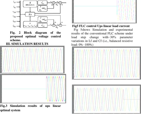
Fig. 2 Block diagram of the proposed optimal voltage control scheme.
III. SIMULATION RESULTS
Fig.3 Simulation results of ups linear optimal system
FIG 3 shows Simulation and experimental results of the proposed observer-based optimal voltage control scheme under load step change with30 %parameter variations in Lf and Cf (i.e., balanced resistive load:0%–100%)
Fig 4 under linear load ,load voltage voltage
Fig 4 shows that Flc control by applying linear load the voltage wave form.
Fig5 FLC control Ups linear load current
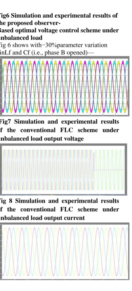
Available online: https://edupediapublications.org/journals/index.php/IJR/ P a g e | 3136 Fig6 Simulation and experimental results of
the proposed observer-
Based optimal voltage control scheme under unbalanced load
fig 6 showswith−30%parameter variation sinLf and Cf (i.e., phase B opened)—
Fig7 Simulation and experimental results of the conventional FLC scheme under unbalanced load output voltage
Fig 8 Simulation and experimental results of the conventional FLC scheme under unbalanced load output current
Fig9 Simulation and experimental results of the proposed observer-based optimal voltage control scheme under nonlinear load Load output voltages (VL)
Fig 10 Simulation and experimental results of the proposed observer-based optimal voltage control scheme under nonlinear load Load output currents(IL)
Fig11 Simulation and experimental results under nonlinear load
Fig shows under nonlinear load PhaseA load current error(ieLA=iLA−ˆiLA)
Fig12 Simulation and experimental results of the conventional FLC scheme under nonlinear load
Fig 12 shows the results of conventional IFLC scheme under non linear load with−30%parameter variations in Lf and Cf (i.e., three-phase diode rectifier
CONCLUSION
Available online: https://edupediapublications.org/journals/index.php/IJR/ P a g e | 3137 using the Lyapunov theory. The superior
performance of the proposed control system was demonstrated through simulations and experiments. Under three load conditions,the proposed control scheme revealed a better voltage tracking performance such as lower THD, smaller steady-state error, and faster transient response than the conventional FLC scheme even if there exist parameter variations.
REFERENCES
[1] A. Nasiri, “Digital Control of Three-Phase Series-Parallel Uninterruptible Power Supply Systems,” IEEE Trans. Power Electron. , Vol. 22, No. 4, Pp. 1116–1127, Jul. 2007.
[2] Y. H. Chen And P. T. Cheng, “An Inrush Current Mitigation Technique For The Line-Interactive Uninterruptible Power Supply Systems,” Ieee Trans. Ind. Appl. , Vol. 46, No. 4, Pp. 1498–1508, May/Jun. 2010kimetal.Optimal Voltage Control Scheme For Three-Phase Ups Systems 2081
[3] K. S. Low and R. Cao, “Model Predictive Control of Parallel-Connected Inverters for Uninterruptible Power Supplies,”IEEE Trans. Ind. Electron., Vol. 55, No. 8, Pp. 2884–2893, Aug. 2008.
[4] A. Mokhtarpour, H. A. Shayanfar, M. Bathaee, And M. R. Banaei, “Control Of A Single Phase Unified Power Quality Conditioner-Distributed Generation Based Input Output Feedback Linearization,”J. Elect. Eng. Technol.Vol. 8, No. 6, Pp. 1352–1364, Nov. 2013.
[5] J. H. Lee, H. G. Jeong, And K. B. Lee, “Performance Improvement Of Grid- Connected Inverter Systems Under Unbalanced And Distorted Grid Voltage By Using A Pr Controller,”J. Elect. Eng. Technol., Vol. 7, No. 6, Pp. 918–925,Nov. 2012.
[6] H. K. Kang, C. H. Yoo, I. Y. Chung, D. J. Won, And S. I. Moon, “Intelligent Coordination Method Of Multiple Distributed Resources For Harmonic Current Compensation In A Microgrid,” J. Elect. Eng. Technol., Vol. 7, No. 6, Pp. 834–844, Nov. 2012.
[7] C. Salim, B. M. Toufik, And G. Amar, “Harmonic Current Compensation Based On Three-Phase Three-Level Shunt Active Filter Using Fuzzy Logic Current Controller,” J. Elect. Eng. Technol., Vol. 6, No. 5, Pp. 595– 604, Sep. 2011.
[8] U. Borup, P. N. Enjeti, And F. Blaabjerg, “A New Space-Vector-Based Control Method For Ups Systems Powering Nonlinear And Unbalanced Loads,” Ieee Trans. Ind. Appl., Vol. 37, No. 6, Pp. 1864–1870, Nov./Dec. 2001.
[9] H. Karimi, A. Yazdani, and R. Iravani, “Robust Control of an Autonomous