Data Transmission Using Barcode Modulation Technique
P Sravani & B Bhargavendra
1Pg Scholar, Department of ECE, Vaageswari College of engineering, Karimnagar
2Assosciate Professor, Department of ECE, Vaageswari College of engineering, Karimnagar.
ABSTRACT
The concept of two-D bar codes is of extraordinary relevance for use in wireless statistics transmission among handheld virtual gadgets. In a well-known setup, any file on a mobile telephone cellphone, for instance, may be transferred to a 2nd mobile phone cellphone through a chain of images at the liquid crystal show which might be then captured and decoded through the digital digicam of the second one telephone cell smartphone. On this have a study, a modern-day-day method for facts modulation in 2-D bar codes is introduced, and its conventional typical overall performance is evaluated in evaluation to unique famous methods of bar code modulation. In this new technique, orthogonal frequency-department multiplexing (OFDM) modulation is used together with differential phase shift keying (DPSK) over adjoining frequency area factors. A completely particular cause of this look at is to installation a device this is proven tolerant to digital digital camera moves, photograph blur, and mild leakage inner neighboring pixels of a liquid crystal display.
1 INTRODUCTION
The telecom employer has grown dramatically within the ultimate six a long time and helps numerous applications
reliability regarded, t right here many upgrades had been made to the real barcode layout. Two-dimensional barcode (2D) or a latest the front matrix has opened for those price-powerful codes and implemented in greater complicated facts switch situations along with storing touch data and URLs among different things, and which code codes can be increasingly famous. Compare 2D barcode overall performance in digital camera smartphone applications. Much effort has been committed to growing the barcode matrix to the barcode displayed on a bit of paper as I usually use. .
2. AIM OF THE PROJECT
In this paper the differential changed into combined with the variable section shift with the orthogonal frequency department i to regulate the facts go with the glide to the two-dimensional optical barcode. It has been shown that the KSC-OFDM configuration has intense shortcomings inside the mitigation of LED digicam moves due to the fact the section of every element changes constantly. On the other hand, the addition of the differential-section modulator previous to modulation to adjust the information flow to the section versions of the adjacent factors (DPSK-OFDM) is increasingly weakening the movement's impact because of its sluggish trade from detail to component, contributing to its small size deviation from the right phase of the signal Receiving.
3.MOTIVATION
Data transfer (virtual bit or virtual analog sign) via a element-to-factor or element-to-multipoint conversation channel. Examples include copper wires, fiber optics, wireless conversation channels, storage media and laptop buses. The
facts is represented as an electromagnetic sign, along with an electrical voltage, radio wave, microwave, or infrared signal. Analog or analogue transmission is a transmission approach for the transmission of voice, facts, photograph, sign or video information the use of a non-forestall sign that varies in amplitude, segment or different property in proportion to a variable. Messages are either represented via a series of pulses via a line code (the baseband transmission), or through a confined set of continuously converting waveforms (sending the scroll range) the usage of a virtual modulation technique. The formation of the nursing band and the elimination of the corresponding configuration (also known as detection) are completed through method m. According to the maximum commonplace definition of digital sign, every primary and extendedband alerts representing bit currents are taken into consideration digital transmissions, whilst an opportunity definition is nice the number one band sign as digital, and the digital range of virtual records switch is converted to analogue
4.TRANSMMISION OF DATA
The capability is a essential a part of the records transmission from the prevent of the transmission to the surrender of the receiver though the channel. The wide variety B is seen at the LED screen and in particular from the raw photograph. A color photograph at the show display which consist of rows and columns "M" and "N" is displayed and records is transmitted through a channel this is deeply represented via bits of colour constant with channel.
As communique systems evolve, the want for better photo rates will become extra said. However, the modern-day multiple get entry to with excessive code prices faces many more than one direction problems, which leads to Isi. Echo is the Co-Pie of the original sign not on time in time. EISI takes area while echoes of numerous period propagation paths cause overlapping of the receiving codes. Problems can arise while one OFFDM code interferes with the subsequent code. There isn't any dating among two consecutive signals, so the overlap of one code with the alternative will bring about a disturbance signal. In addition, the price of symbols in conversation systems is confined to sincerely the channel bandwidth. For better picture charges, Icy's outcomes should be treated significantly. Many channel offset strategies can be used to suppress channel-delivered on ES gadgets. However, to accomplish that, the heart beat response of the channel ought to be predicted. In addition, once the incoming signal is break up into the sub-groups of the transmission, a shield interval is delivered among each code. Each code is beneficial, wherein, the duration of the image l, Tissiand the guard duration, a part of the time, the Tissi sign is repeated periodically. Since multi-segment propagation delays do no longer exceed the duration, there may be no overlap among symbols and no channel equation is wanted.
4.2 Interference, distortion and noise
When the use of the digicam to seize a photograph of 2D barcode, some artifacts will have an effect on the photo stop result of the facts extraction approach. These artifacts are specifically attributed to the following distance and attitude some of the digital camera and the
LCD (• Distortion mind-set); digital camera and relative movement project
• Out of consciousness lens.
• Pressure deformities
• Ambient slight property
• Dirt and everlasting markers on the LCD
• Noise (more gucci noise in the first area).
• Furthermore, there are non-linear distortions within the guidance of standard optical transmission facts because of the bodily constraints of transmitter and receiver cited in. These unwanted consequences ought to be addressed to make certain the feasibility of the set of regulations beneath realistic conditions, whilst keeping the potential to advantage excessive facts switch charges
Generation of Csk: Here i / p binary sequence. They are first converted right into a bipolar sign shape of signal. This reference is referred to as (t). Returns the binary "1" by way of "+ 1V" and the binary "0" via "-1V". The complex is split into two separate bits of character numbered or even numbered bits. Here represents (t) even a numbered series and represents a bo (t) numbered numbered series. The length of the image for each of these character numbered sequences is two terabytes. Thus, every code consists of 2 bits.
includes error correction codes. These help a QR reader, to accurately read the code, even if part of it is unreadable. This is done by creating some redundant data that is generated when a QR code is encoded. Error corrections are of four levels. The lowest is L, which allows the code to be read even if 7 percentage of it is unreadable. After that is M, which gives 15 percentage error correction, then Q, which provides 25 percentage, and finally H, which gives 30 percentage. The capacity of a given QR code depends on three factors: the version, error correction level and the type of data that is encoded. A QR code can encode four types of data modes: numeric, alphanumeric, binary, or Kanji. [10]. The algorithm for QR code is as shown. Step 1: Data analysis: Choose proper mode for encoding data. Step 2: Data encoding: Data is encoded in the desired mode. Step 3: Error correction coding: Suitable error correction code words are selected. Step4: Structure final message: Both data and error correction code words are arranged into final message. Step5: Module placement: These message bits are arranged in the form of a matrix. Step 6: Data masking: Suitable data mask pattern is selected. Step7: Add format and version string Step8: Add quiet zone
5.1.ReceiverIn the receiver, this QR code is demodulated and decrypted to obtain the actual message. The cyclic prefix is removed before demodulation and FFT is taken. Using the constellation mapping used at the transmitter, the original data bits are retrieved. Image capturing: The encrypted modulated QR code which is displayed on the LCD of the first phone is captured using the camera of another phone. This QR code can be detected with the help of finder patterns. QR code decoder: The encrypted
modulated QR code is decoded to obtain the encrypted modulated message. Demodulation and decryption is performed in this message. Removal of cyclic prefix: The bits that were added in the transmitter side as the cyclic prefix are removed. FFT: On taking the FFT, time domain signal is converted to frequency domain signal. The frequency domain data comprises of the differential phase modulated elements. Let this matrix be R.
DPSK demodulation: From the matrix R, the phase difference is extracted as follows.
Calculate the input bit: Each input bit is calculated using the constellation map of the transmitter. Now these input bits are decrypted to obtain the data. Thus the QR code is captured without much motion blur and the message is retrieved.
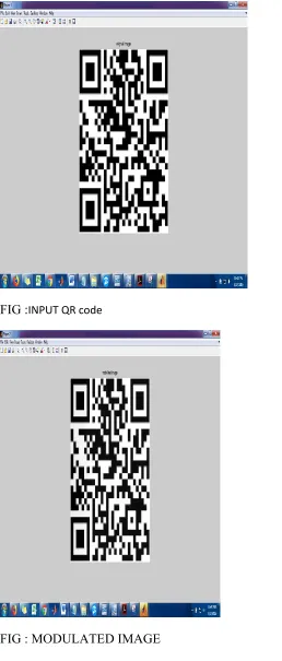
EXPERIMENTAL RESULTS:
FIG :INPUT QR code
FIG : MODULATED IMAGE
CONCLUSION AND FUTURE WORK A
data can be securely transferred from one mobile device to another by first encrypting it and then converting the data into barcodes. This is then transferred to another device by capturing the image of the barcode. This data transfer uses visual light communication, thus reducing the possibilities of NFC attacks. In order to avoid motion blur distortions, the data is stored in phase difference of adjacent elements. The data transfer rate can be increased by increasing the bits per symbol from current 2 bits per symbol constellation.
REFERENCES
[1] M. Allah, “Strengths and weaknesses of near field communication (nfc) technology,” GJCST, vol. 11, no. 3, 2011.
[2] H. Kato and K. Tan, “Pervasive 2d barcodes
for camera phone
applications,”PervasiveComput., vol. 6, no. 4, pp. 76–85, Oct. 2007.
[3] X. Liu, D. Doermann, and H. Li, “Vcode-pervasive data transfer using video barcode,” IEEE Trans. Multimedia, vol. 10, no. 3, pp. 361– 371, Apr. 2008.
[4] S. D. Perli, N. Ahmed, and D. Katabi, “Pixnet: Interference- free wireless links using LCD-camera pairs,” in Proc. MobiCom, 2010, pp. 137–148.
[6] M.Mondal and J. Armstrong, “Impact of linear misalignment on a spatial OFDM based pixelated system,” in Proc. 18th Asia-Pacific Conf. Commun., Oct. 2012, pp. 617–622.
[7] M. Mondal and J. Armstrong, “The effect of defocus blur on a spatial OFDM optical wireless communication system,” in Proc. 14th Int. Conf. Transparent Opt. Netw., Jul. 2012, pp. 1–4.
[8] M. R.H.Mondal and J.Armstrong, “Analysis of the effect of Vignetting on mimo optical wireless systems using spatial OFDM,” J. Lightw. Technol., vol. 32, no. 5, pp. 922–929, Mar. 1, 2014.
[9] Amin Motahari and
MalekAdjouadi.“Barcode modulation method for data transmission in mobile devices” IEEE Trans. on Multimedia. vol. 17, no. 1, Jan. 2015.