Conjoined, 2.4/5-GHz WLAN Two-Monopole System Decoupled
Using Mode-Controlled Capacitor for Notebook Computers
Che-Chi Wan and Saou-Wen Su*
Abstract—A low-profile, decoupled two-monopole system with its two parasitic grounded strips conjoined, forming a very compact structure is demonstrated. Each of the two identical antennas comprises a driven coupling strip and a parasitic grounded strip, operating respectively in the 2.4 GHz (2400–2484 MHz) and 5 GHz (5150–5825 MHz) wireless local area network (WLAN) bands. The two parasitic strips are further joined together, becoming a central, grounded T monopole. By loading a capacitor between the T monopole and the antenna ground, the mutual coupling in the 2.4 GHz band can be reduced by about 12 dB. The capacitor in this design is used to control Ant2 monopole mode to cancel out opposite-phased currents of the dipole mode on the T monopole when Ant1 is excited, such that isolation enhancement can be attained. The proposed two-monopole system occupies a compact size of 5 mm×40 mm (about 0.04λ×0.32λat 2.4 GHz) and is favorable for applications in the narrow-bezel notebook computers owing to its low profile of 5 mm.
1. INTRODUCTION
The demands for higher data rates have increased over a decade. This translates into the requirement of using multiple antennas inside wireless devices to gain more spatial streams in the complex propagation environment. For example, four wireless local area (WLAN) antennas are deployed in the gaming notebook computers to provide more antenna pattern selections for achieving better throughput performance [1]. It is forecasted that future notebook computers will be installed with more than two WLAN antennas for the soon IEEE 11ax communications [2]. For the antenna engineers, this becomes very challenging to further distribute more antenna elements inside the devices because very little space is left for the current notebook computers. For the rationale of limited space, placing two antennas in close proximity (usually less than quarter-wavelength in free space [3]) becomes a feasible solution.
To improve antenna port-to-port isolation, one popular decoupling technique in common practice is to introduce additional coupling path against the original antenna coupling by inserting grounded resonator structures between the antennas as in [4–9]. The decoupling structures include the uses of the meandered strip resonator [4], the T-shaped open slot in the protruded ground [5], the T-shaped decoupling structure [6], the combination of the meandered strip and the T-shaped open slot [7], the same radiator as the decoupling structure [8], and the integrated π-shaped decoupling strip [9]. A different decoupling technique that uses an inductor connecting the open ends of the shorted monopoles is also reported for notebook applications [10]. Another decoupling technique without placing any decoupling structure between antennas is reported as a self-curing technique [11], in which the capacitive load at proper locations on the shorting strips of the inverted-F antennas with the edge-to-edge distance of 9 mm. The most obvious advantage of designing two separate antennas in a two-antenna system is that
Received 30 August 2019, Accepted 19 November 2019, Scheduled 27 November 2019
* Corresponding author: Saou-Wen Su (Saou-Wen [email protected]).
between the two antennas are presented in [12]. It is shown that the conjoined section embedded with a capacitor acts like a band-pass structure, which attracts the currents on the ground, when one loop is excited, distributed on this section and not entering the other loop owing its much lower impedance and thereby decouples the antennas. However, the impedance bandwidth covers the single band of the 5G new-radio band (NR) 77 (3300–4200 MHz), and the isolation therein is just better than 12 dB. The antenna height of 6 mm (about 0.07λat 3.3 GHz) is also larger than 5 mm and can not fit in the narrow bezels of recent notebook computers [13–16].
In this paper, we demonstrate a low-profile, conjoined two-monopole antenna system capable of operating in the 2.4/5 GHz WLAN band with isolation better than 19 and 16 dB over the 2.4 and 5 GHz bands and showing a compact size of 5 mm × 40 mm (about 0.04λ×0.32λ at 2.4 GHz). The design comprises two symmetrically identical monopoles, formed by one 5 GHz driven coupling strip and one 2.4 GHz parasitic grounded strip. The parasitic strips are further conjoined, becoming a central, grounded T monopole. By loading a chip capacitor between the T monopole and the antenna ground, the mutual coupling in the 2.4 GHz band can be reduced by about 12 dB (from 7 to 19 dB). Moreover, the two 5 GHz driven strips are inherently decoupled owing to larger distance between them. The capacitor in this study neither function as a band-pass resonant structure as reported in [12] nor is considered as one of the two discrete auxiliary ports in the impedance matrix as calculated in [11]. Substantially different, the capacitor allows the conjoined strips (T monopole) to generate two different resonant modes very close to each other with similar magnitude but out-of-phase surface currents on the parasitic strip of one antenna (Ant2) when the other antenna (Ant1) is excited. Good decoupling between the antennas is thereby attained. A comparison table for the previous work in [4–12] is provided. From Table 1, it can be seen that the proposed design shows a low profile of 5 mm with no separation between antennas and yet offers minimum isolation >16 dB for every band. Details of the design are described, and the results thereof are discussed in the article.
Table 1. Comparison of the two-antenna systems [4–12] regarding the operating bands, the overall antenna size, the separation distance between antennas, and the minimum isolation for every band.
Ref. Operating bands Size of height ×length Antenna separation Isolation*
[4] 2.4/5.2/5.8 GHz 9 mm×50 mm 24 mm 18.5 dB
[5] 2.4/5.2/5.8 GHz 9 mm×40 mm 26 mm 18 dB
[6] 2.4/5.2/5.8 GHz,
2.5/3.5/5.5 GHz 9 mm×54 mm 25.6 mm 15 dB
[7] 2.4/5.2/5.8 GHz 7.5 mm×46.4 mm 14.4 mm 15 dB
[8] 2.4/5.2/5.8 GHz 5 mm×40 mm 16 mm 15 dB
[9] 2..4/5.2/5.8 GHz 5 mm×38 mm 2 mm 16 dB
[10] 2.4/5.2/5.8 GHz 5 mm×42 mm 1 mm 17 dB
[11] 2.4 GHz 10 mm×43.2 mm 9 mm 16 dB
[12] 3.3–4.2 GHz (5G NR77) 6 mm×20 mm no separation 12 dB
proposed 2.4/5.2/5.8 GHz 5 mm×40 mm no separation 16 dB
2. PROPOSED TWO-MONOPOLE SYSTEM
2.1. Antenna Configuration and Design Consideration
t
port2
copper tape
metal plate of display two-monopole system
port1
capacitor
(a) (b)
(c)
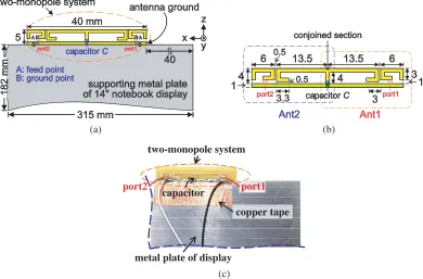
Figure 1. (a) Geometry of the conjoined, dual-WLAN-band two-monopole system affixed to the top edge of the supporting metal plate of a 14-inch notebook display. (b) Detailed dimensions of the design prototype. (c) Photo of the fabricated prototype.
plate, coated with the zinc for solderability and can function as the large system ground for both the antennas and the electromagnetic interference (EMI) grounding. The proposed design is fabricated on a 0.4-mm-thick, flame retardant 4 (FR4) substrate (εr = 4.4) of size 5 mm ×40 mm only and spaced 40 mm apart from the top-right corner of the metal plate. This 40 mm clearance area is reserved for the mechanical structures, not available for any antenna placement. The small antenna ground of size 1 mm ×40 mm is also considered in the design footprint as it is required to be connected to the large system ground via small copper tape for practical applications.
(a) (b)
(c) (d)
Figure 2. Simulated S parameters (S11 for Ant1, S22 for Ant2, S21 isolation between two antennas)
for (a) proposed design, (b) reference case 1 (Ant1, proposed without Ant2), (c) reference case 2 (Ant1 and Ant2 spaced 1 mm apart), and (d) reference case 3 (proposed without capacitor C);C= 2.4 pF.
2.2. Controlling Mechanisms
To understand the decoupling mechanisms of the design, several reference cases are analyzed. Fig. 2 shows the simulatedS-parameters for the proposed design, reference case 1 (single monopole), reference case 2 (Ant1 and Ant2 spaced 1 mm apart), and reference case 3 (proposed without capacitor); all the dimensions are kept the same as those shown in Fig. 1. First, for the proposed design, two resonant modes respectively in the 2.4 and 5 GHz bands with isolation (S21) better than 18 and 15 dB are
generated. For Ant1 only as in reference case 1, the reflection coefficient in Fig. 2(b) is almost the same as those (see S11, S22 curves) in Fig. 2(a). This suggests that the achievable impedance bandwidth
for the individual antenna is not much affected when the two monopoles are joined together for the proposed design. Notice that the capacitor still has the effect on the antenna frequencies in the lower band (see the black circle curve for reference 1 without C) and thus, are reserved for the studies in reference cases 1 and 2. In the case of duplicating Ant1 and symmetrically placing it as Ant2 in close proximity (1 mm gap), the two discrete antennas in Fig. 2(c) have poor isolation at about 9 dB in the 2.4 GHz band, which is caused by strong coupling between the two parasitic strips [see Fig. 4(a)].
The capacitor in this design controls the occurrence of the monopole mode for Ant2 to be very close to the dipole mode in the central T monopole. The monopole mode of Ant2 has the opposite-phased currents opposed by those of the dipole mode when Ant1 is excited. As a result of the two resonant modes of almost the same magnitude but with the opposite phases, the mutual coupling can be reduced [18]. The decoupling mechanisms for the design are further elaborated with the aid of Figs. 3 and 4. In Fig. 3, two largely different-scaled values (1.0 vs. 10 pF) of the capacitor are practically selected from the datasheet of Murata GJM series, and two resonant modes can be observed in the 2–3 GHz frequency range. The resonant mode around 2.4 GHz is identified as the dipole mode, formed by the horizontal portions of the two parasitic strips as shown in Figs. 4(c) and (d) and does not move drastically as the values of the capacitor varies. On the other hand, when the capacitor C increases from 1.0 to 10 pF, the frequencies of the monopole modes for both antennas shift toward the lower frequencies, even below 2.4 GHz [see resonance at 2120 MHz in Fig. 3(b)]. In these cases, the isolation also becomes very poor. Only when these two modes (dipole and monopole) becomes very close to each other can good isolation be attained.
(a) (b)
Figure 3. Simulated S parameters for the proposed design in the case of (a) C = 1.0 pF and (b) C= 10 pF.
f= 2445 MHz (separate monopole modes)
f= 2445 MHz (separate monopole modes)
(a)
f= 2200 MHz
central monopole mode)
(b)
f= 2435 MHz (dipole mode)
f= 2815 MHz (monopole mode)
(c)
f= 2120 MHz
(monopole mode)
f= 2395 MHz
(dipole mode) (d) PORT1
PORT1
PORT2
PORT2 PORT1PORT1
PORT
PORT1 PORT2
PORT2 PORT1
PORT2 PORT1
PORT1 PORT2
monopole mode). The surface currents on the horizontal portions of the two parasitic strips flow, in the same direction, through the top portion of the central T monopole when the two parasitic strips are conjoined. This phenomenon results in the dipole mode around 2.4 GHz as seen in Figs. 4(c) and (d). Notice that this dipole mode can only occur when the T monopole is coupling fed by a driven strip. If the signal port is given to the T monopole without any driven strips [see Fig. 4(b)], the surface currents on the T monopole are in the same phase (from the signal to two open ends), resembling the properties of the surface current for the monopole modes in Figs. 4(c) and (d).
Also notice that from the input impedance curves at 2200 MHz where the zero reactance occurs, the resistance for the central monopole mode studied in Fig. 4(d) is very small at about 8 Ω (results not shown for brevity). This behavior suggests that for reference case 3 studied in Fig. 2(d), the dipole mode is the dominant resonance and the monopole mode is not responsive. Finally, from these results shown in Figs. 2, 3, and 4, it can be concluded that with the use of the mode-controlled capacitor loaded between the parasitic strip and the antenna ground, isolation enhancement in the 2.4 GHz band can be attained by about 12 dB (from 7 to 19 dB).
3. EXPERIMENTAL AND SIMULATION RESULTS
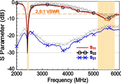
Figure 5 shows the measured and simulated S-parameters for the proposed two-antenna system. The simulation is presented by gray dashed lines. The targeted 2.4 and 5 GHz WLAN bands are marked by the shaded frequency ranges. The experimental data in general agree with the simulation. The reflection coefficients,S11 andS22, in the bands of interest are all below−7.4 dB (VSWR of 2.5), which
corresponds to about 0.8 dB transmission loss via the antenna and is industrially acceptable for WLAN notebook antennas. The measured isolation (S21) between the antennas is better than 19 and 16 dB
over the 2.4 and 5 GHz bands. Notice that the 50-Ω mini-coaxial cables of length about 80 mm were used for feeding the monopoles. The inner conductor of the cable is connected to the feed point (point A) of the monopole while the outer grounding is soldered at the ground point (point B), opposite to the feed point with a feed gap of 1 mm, on the antenna ground. The feed point and the ground point for Ant1 and Ant2 are shown in Fig. 1(a).
Figure 5. Measured and simulated (gray dash lines) S parameters for the proposed two-monopole system; C= 2.4 pF.
f= 2445 MHz PORT1 PORT2
PORT1
PORT2 f= 5490 MHz
f= 2445 MHz PORT1
PORT2
PORT1
PORT2 f= 5490 MHz
(a)
f= 2445 MHz PORT1
PORT2
PORT1
PORT2 f= 5490 MHz
f= 2445 MHz PORT1
PORT2
PORT1
PORT2 f= 5490 MHz
(b)
Figure 6. Simulated surface currents for Ant1 excited at 2445 and 5490 MHz in the (a) proposed design and (b) reference case 3.
(a)
(b)
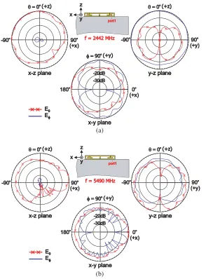
Figure 7. Measured 2D radiation patterns of Ant1 in the proposed design at (a) 2442 MHz and (b) 5490 MHz.
(a)
(b)
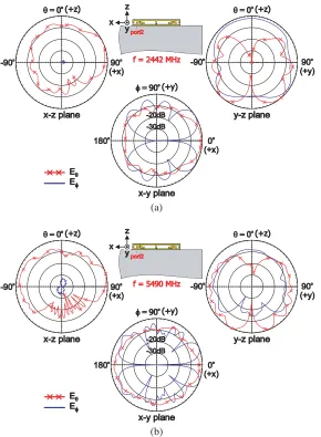
Figure 8. Measured 2D radiation patterns of Ant2 in the proposed design at (a) 2442 MHz and (b) 5490 MHz.
isolation in the lower band.
The over-the-air (OTA) performance of the fabricated prototype was measured at our SATIMO chamber of model SG 64, which uses the conical-cut method and has multiple probe arrays [19]. Figs. 7(a), (b) and 8(a), (b) show the measured radiation patterns in Eθ and Eϕ fields for Ant1 and Ant2, respectively, at 2442 and 5490 MHz, the center frequencies of the 2.4 and 5 GHz bands. During the measurement for Ant1 or Ant2, the counterpart Ant2 or Ant1 was terminated at the 50-Ω load connector. First, comparable Eθ and Eφ fields are observed in the x-y planes, which is beneficial for WLAN operation in the complex propagation environment. Second, the radiation patterns in the elevation planes (x-z and y-z planes) show larger radiation toward the +z direction above the display, similar to the radiation characteristics of the WLAN, monopole notebook antenna as studied in [13].
Figure 9. Measured peak antenna gain and antenna efficiency for Ant1 and Ant2 studied in Figs. 7 and 8.
the cable loss; the realized gain [20] and the antenna efficiency [21] are measured in the chamber. The efficiency was also obtained by calculating the total radiated power of the antenna over the spherical radiation and dividing that total amount by the input power of 0 dBm given to the antenna under test.
4. CONCLUSION
A conjoined two-monopole system suitable for narrow-bezel, notebook applications for dual-band WLAN operation has been proposed. The design comprises two driven coupling strips, one T monopole formed by conjoining two parasitic grounded strips, and one mode-controlled capacitor loaded between the T monopole and the antenna ground, all printed on the substrate of size 5 mm×40 mm. The driven strips mainly generate the upper band for 5 GHz operation while the parasitic strips are used to excite the 2.4 GHz band. The chip capacitor is introduced to move the monopole mode for one antenna (Ant2) very close to the dipole mode in the T monopole when the other antenna (Ant1) is excited, creating out-of-phase currents but with similar magnitude on Ant2 and thereby improving the isolation properties in the 2.4 GHz band. The measured port isolation is better than 19 and 16 dB over the 2.4 and 5 GHz bands. The antenna efficiency in the 2.4 and 5 GHz bands exceeds 63% and 57% for Ant1 and 58% and 57% for Ant2. The proposed two-monopole system is promising for future multiple notebook antennas for Gbps communications.
REFERENCES
1. RangBoost technology, ASUS, https://www.asus.com/Laptops/ ROG-Strix-Hero-II/.
2. Khorov, E., A. Kiryanov, A. Lyakhov, and G. Bianchi, “A tutorial on IEEE 802.11ax high efficiency WLANs,”IEEE Comm. Surveys &Tutorials, Vol. 21, 197–216, 2019.
3. Mak, A. C. K., C. R. Rowell, and R. D. Murch, “Isolation enhancement between two closely packed antennas,”IEEE Trans. Antennas Propagat., Vol. 56, 3411–3419, 2008.
4. Kang, T. W. and K. L. Wong, “Isolation improvement of 2.4/5.2/5.8 GHz WLAN internal laptop computer antennas using dual-band strip resonator as a wavetrap,” Microw. Opt. Technol. Lett., Vol. 52, 58–64, 2010.
5. Guo, L., Y. Wang, Z. Du, Y. Gao, and D. Shi, “A compact uniplanar printed dual-antenna operating at the 2.4/5.2/5.8 GHz WLAN bands for laptop computers,” IEEE Antennas Wireless Propagat. Lett., Vol. 13, 229–232, 2014.
6. Liu, Y., Y. Wang, and Z. Du, “A broadband dual-antenna system operating at the WLAN/WiMax bands for laptop computers,”IEEE Antennas Wireless Propagat. Lett., Vol. 14, 1060–1063, 2015. 7. Deng, J. Y., J. Y. Li, L. Zhao, and L. X. Guo, “A dual-band inverted-F MIMO antenna with
integrated π-shaped decoupling structure,” IEEE Trans. Antennas Propagat., Vol. 67, 6182–6186, 2019.
10. Su, S.-W., C. T. Lee, and S. C. Chen, “Very-low-profile, triband, two-antenna system for WLAN notebook computers,”IEEE Antennas Wireless Propagat. Lett., Vol. 17, 1626–1629, 2018.
11. Sui, J. and K. L. Wu, “Self-curing decoupling technique for two inverted-F antennas with capacitive loads,”IEEE Trans. Antennas Propagat., Vol. 68, 1093–1101, 2018.
12. Wong, K. L., B. W. Lin, and S. E. Lin, “High-isolation conjoined loop multi-input multi-output antennas for the fifth-generation tablet device,” Microw. Opt. Technol. Lett., Vol. 61, 111–119, 2019.
13. Su, S.-W., “Very-low-profile, 2.4/5-GHz WLAN monopole antenna for large screen-to-body-ratio notebook computers,”Microw. Opt. Technol. Lett., Vol. 60, 1313–1318, 2018.
14. Su, S.-W., C. T. Lee, and S. C. Chen, “Compact, printed, tri-band loop antenna with capacitively-driven feed and end-loaded inductor for notebook computers,” IEEE Access, Vol. 6, 6692–6699, 2018.
15. Su, S.-W., “Capacitor-inductor-loaded, small-sized loop antenna for WLAN notebook computers,” Progress In Electromagnetics Research M, Vol. 71, 179–188, 2018.
16. Su, S.-W., “Very-low-profile, small-sized, printed monopole antenna for WLAN notebook computer applications,” Progress In Electromagnetics Research Letters, Vol. 82, 51–57, 2019.
17. ANSYS HFSS, ANSYS Inc., https://www.ansys.com/Products/Electronics/ANSYS-HFSS. 18. Li, M., L. Jiang, and K. L. Yeung, “Novel and efficient parasitic decoupling network for closely
coupled antennas,”IEEE Trans. Antennas Propagat., Vol. 67, 3574–3585, 2019.
19. SG 64, SATIMO, http://www.mvg-world.com/en/products/field product family/antenna-measurement-2/sg-64.
20. Volakis, J. L., Antenna Engineering Handbook, 4th Edition, Chapter 6, 16–19, McGraw-Hill, New York, 2007.
![Table 1. Comparison of the two-antenna systems [4–12] regarding the operating bands, the overallantenna size, the separation distance between antennas, and the minimum isolation for every band.](https://thumb-us.123doks.com/thumbv2/123dok_us/1965729.1259248/2.612.76.545.460.641/comparison-regarding-operating-overallantenna-separation-distance-antennas-isolation.webp)