Controlling the Optical Bistability and Multistability
via Atom Localization
Marziye Moghannian, Azar Vafafard*, and Mohammad Mahmoudi
Abstract—We investigate optical bistability (OB) and optical multistability (OM) behaviors in a triply driven five-level atomic system. It is shown that the system has bistable behavior and can be controlled by intensity of applied fields. We find that OB switches to OM via interference induced among the Rabi-split resonance. We consider a superposed one-dimension standing wave, generated by two optical fields, and it is demonstrated that the OB and OM behaviors depend on the position of localized atoms as well as the relative phase of applied fields.
1. INTRODUCTION
Atomic coherence plays an important role in controlling the optical properties of the mediums because of its potential applications in optical physics. One interesting application is optical bistability (OB) which can be used in all optical switching and optical computing [1]. Optical bistable system exhibits two possible outputs for the same input intensity which are suitable for controlling the light by light. Different mechanisms have been used for preparing OB in various systems. One of these techniques is acousto-optical (AO) interaction which includes an optoelectronics feedback system [2, 3]. In this technique, OM and even chaos have been observed which are useful in the encryption/decryption blocks of a digital communication system [4]. The second mechanism is a simple Fabry-Perot resonator or ring cavity filled with a material whose refractive index is intensity-dependent [5]. Such bistable behavior is the result of nonlinearity of the atomic medium inside the cavity and feedback of the optical field from the cavity mirrors. In past three decades, optical transistors, all-optical switching and all-optical storage devices based on OB in two-level atomic systems have been extensively studied both experimentally and theoretically [1, 6, 7]. The OB in a three-level V-type atomic system in the presence of vacuum quantum interference has been investigated in multi-photon resonance condition [8, 9] and beyond it [10]. Moreover, the double dark resonance has been used for controlling the OB behavior in a four-level atomic system [11, 12]. Recently, we have reported phase-controlled OB via electromagnetically induced absorption in a four-level double V-type closed-loop system, and it was shown that OB switches to OM via applying a microwave field [13].
On the other hand, the optical properties of a triply driven five-level atomic system have been investigated, and the coherent control of narrow structures in absorption and dispersion was reported [14]. In this paper, we study the OB and OM behaviors of such a system, and it is shown that the OB behavior can be controlled by intensity of applied fields. In addition, it is demonstrated that by applying a microwave field to the system, OB switches to OM via interference induced among the Rabi-split resonance. Moreover, the effect of transverse standing cavity field on OB and OM in a unidirectional ring cavity is studied, and it is shown that the position of localized atom plays a major role in determining of the bistability and multistability behaviors of the system.
Received 31 August 2015, Accepted 7 January 2016, Scheduled 16 January 2016
* Corresponding author: Azar Vafafard ([email protected]).
2. MODEL AND EQUATIONS
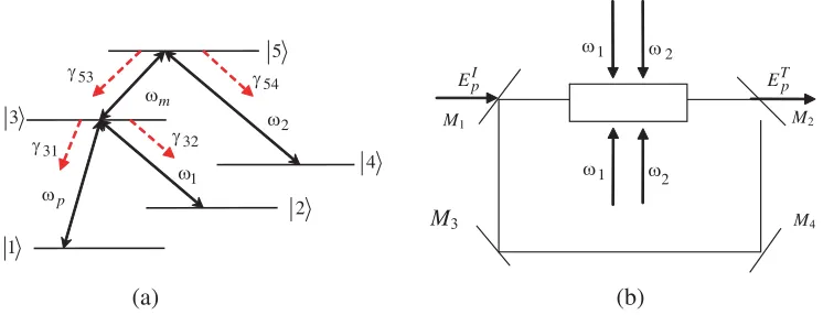
We consider a triply driven five-level atomic system as shown in Fig. 1(a). In this scheme, the probe field is applied to the transition |1–|3 of frequency ω31 with frequency ωp and amplitude Ep. Two
coherent coupling fields with frequencyω1, ω2and amplitudeE1, E2 are applied to the transitions|2–|3
of frequencyω32 and |4–|5 of frequency ω54, respectively. All three laser beams can be generated by
a single laser, using electro-optical modulators. The transition |3–|5 of frequency ω53 is excited by a
microwave field with frequencyωm and amplitudeEm. The energy levels|2and|4are assumed purely metastable states. Such a system can be generated in D1 transitions of cold 87Rb atoms in a vapor
cell. The lower levels are considered as |1 = 5S1/2(F = 1, mF = −1), |2 = 5S1/2(F = 1, mF = 1) and |3 = 5P1/2(F = 2, mF = 1). Upper levels are two hyperfine levels |3 = 5P1/2(F = 1) and
|5 = 5P1/2(F = 2) separated by 816 MHz. Here F is the total atomic angular momentum quantum
numbers. mF stands for magnetic quantum number of corresponding state.
The Hamiltonian of the system in the interaction picture by using the rotating wave and dipole approximations are expressed by the following equation
H = −[(ΔP −Δ1)|2 2|+ ΔP|3 3|+ (ΔP + Δm−Δ2)|4 4|+ (ΔP + Δm)|5 5|
+(Rp|1 3|+R1|2 3|+Rm|3 5|+R2|4 5|+H·C)] (1)
In this equation, the detuning and Rabi frequency of applied fields are defined as
Δ1 = ω1−ω32, Δ2 =ω2−ω54, Δm =ωm−ω53, Δp =ωp−ω31, (2)
R1 = μ23·
E1
2 , R2 =
μ45·E2
2 , Rm=
μ35·Em
2 , Rp=
μ13·Ep
2 , (3)
where μ23, μ45, μ35 and μ13 show the dipole moment of transitions |2 → |3, |4 → |5, |1 → |3 and |3 → |5 respectively.
The density matrix equations of motion are given by ˙
ρ11=iRp(ρ31−ρ13) +γ31ρ33,
˙
ρ22=iR1(ρ32−ρ23) +γ32ρ33,
˙
ρ33=iRp(ρ13−ρ.31) +iR1(ρ23−ρ32) +iRm(ρ53−ρ.35)−(γ31+γ32)ρ33+γ53ρ55,
˙
ρ44=iR2(ρ54−ρ45) +γ54ρ55,
˙
ρ55=iRm(ρ35−ρ53) +iR2(ρ45−ρ54)−(γ53+γ54)ρ55,
˙
ρ21=i(Δp−Δ1)ρ21+iR1ρ31−iRpρ23,
˙
ρ31=−(Γ31−iΔp)ρ31+iRp(ρ11−ρ33) +iR1ρ21+iRmρ51,
˙
ρ32=−(Γ32−iΔ1)ρ32+iR1(ρ22−ρ33) +iRpρ12+iRmρ52,
˙
ρ41=i(Δp+ Δm−Δ2)ρ41+iR2ρ51−iRpρ43,
˙
ρ42=i(Δ1+ Δm−Δ2)ρ42+iR2ρ52−iR1ρ43,
˙
ρ43=−(Γ43−i(Δm−Δ2))ρ43−iRpρ41−iR1ρ42−iRmρ45+iR2ρ53,
˙
ρ51=−(Γ51−i(Δm+ Δp))ρ51−iRpρ53+iRmρ31+iR2ρ41,
˙
ρ52=−(Γ52−i(Δm+ Δ1))ρ52−iR1ρ53+iRmρ32+iR2ρ42,
˙
ρ53=−(Γ53−iΔm)ρ53+iRm(ρ33−ρ55) +iR2ρ43−iRpρ51−iR1ρ52,
˙
ρ54=−(Γ54−iΔ2)ρ54+iR2(ρ44−ρ55) +iRmρ34,
(4)
where Γ31 = Γ32 = Γ43 = (γ31+2γ32), Γ51 = Γ52 = Γ54 = (γ53+2γ54), Γ53 = (γ31+γ32+2γ53+γ54) are the
31
γ γ32
53 γ 54 γ m ω p
ω ω1
2 ω 1 2 3 4 5 2 ω 1
ω ω2
1
ω
I p
E ETp
M2
M3 M4
M1
(a) (b)
Figure 1. (a) Diagram of five-level atomic system which is driven by a probe field with frequency ωp and three coherent coupling field with ωi(i= 1,2, m). The red arrows stand for decay rates. (b)
Unidirectional ring cavity with atomic sample of lengthL. EPI andEPT are the incident and transmitted fields, while ω1 and ω2 are the central frequency of coupling fields. For mirrors 1 and 2 it is assumed
that ¯R+ ¯T = 1 and mirrors 3 and 4 have perfect reflectivity.
Now, we introduce the eigenvalues of dressed states established by the applied fields which have a key role in understanding of the optical properties of the system. For resonance condition, the atom-field eigenvalues can be written as
Λ1= 0,
Λ2=−
R2
1+R22+R2m−
R4
1−2R21(R22−Rm2 ) + (R22+R2m)2 √
2 ,
Λ3=
R2
1+R22+Rm2 −
R4
1−2R21(R22−R2m) + (R22+Rm2 )2 √
2 ,
Λ4=−
R2
1+R22+R2m+
R4
1−2R21(R22−Rm2 ) + (R22+R2m)2 √
2 ,
Λ5=
R2
1+R22+Rm2 +
R4
1−2R21(R22−R2m) + (R22+Rm2 )2 √
2 .
(5)
ForR1= 0 the eigenvalues are simplified to
λ1=λ2 =λ3= 0,
λ4=−
R2
2+R2m,
λ5=
R2 2+R2m.
(6)
Note that in the presence of R1, only one zero eigenvalue is obtain and can establish a transparency
window in absorption spectrum, accompanied by four peaks. By switching offR1, three zero eigenvalues
are generated and can generate a sharp peak due to the interacting dark resonance.
Now, we are going to study the optical bistability behavior of the system by considering N such five-level atoms inside the unidirectional optical ring resonator depicted in Fig. 1(b). Then under slowly varying envelope approximation, the dynamic response of the probe field is governed by Maxwell’s equation [15]
∂Ep ∂t +c
∂Ep ∂z =i
ωp
2ε0
P(ωp) (7)
where c and ε0 are the light speed and permittivity of free space, respectively. P(ωp) is the induced
According to the mean-field limit and using the boundary condition the input-output relationship is given by
y= 2x−iCγ31ρ31, (8)
wherex=μ31EpT
√T¯ and y=μ31EI p
√T¯ are the normalized output and input fields respectively. The parameter C = LNωPμ2312cε0γ31T¯ is the atomic coupling parameter in a ring cavity, and L
stands for the length of the atomic sample.
3. RESULTS AND DISCUSSIONS
In this section, we discuss the numerical results for obtaining the optical properties of the system under various conditions. We assume γ31 =γ32=γ53 =γ54=γ = 1 and all parameters are scaled by γ. We
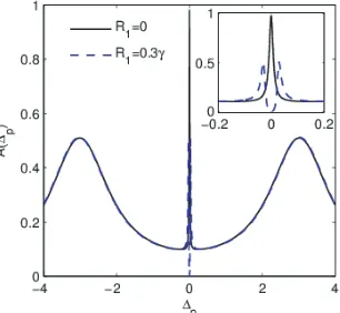
choose a case with symmetric decay rates for reducing the number of parameters in our calculation, and this assumption is not critical for the appearance of the observed multistability in this system. First, we assume that the fieldsE1 andE2 are in the resonance condition. In Fig. 2, we show the absorption of the
probe field versus probe field detuning for different values of Rabi frequency. The selected parameters areRm= 3γ, R2= 0.3γ, Rp = 0.01γ, Δm= Δ1 = Δ2= 0, R1 = 0 (solid) and R1 = 0.3γ (dashed). An
investigation on Fig. 2 shows that the absorption of the probe field is affected by applying the fieldE1
to the system. An absorption peak due to the constructive interference in the three-photon process is appeared for R1 = 0 at the Δp = 0. This structure is explained according to the Equation (6). When
field E1 is turned on, the sharp absorption peak splits into a closely spaced absorption doublet, and a
central transparent window due to the four-photon resonance is established which is shown by dashed curve in Fig. 2. The results are in good agreement with Fig. 2 of [14]. Note that the position of four peaks can be determined by the four eigenvalues of the system, which have been introduced in Equation (5).
In Fig. 3, we show the OB behavior of the system in resonance condition in (a) absence and (b) presence of the field E1 for different values of the probe field detuning. Used parameters areC = 200,
Δp = 0 (solid), Δp = 0.025γ (dashed), Δp = 0.05γ (dash-dotted) for (a) R1 = 0 and (b) R1 = 0.3γ.
Other parameters are the same as in Fig. 2. In Fig. 3(a), it is shown that increase of Δp leads to a decrease of the bistablity threshold. We find that, in the presence of the field E1, one can transit
between bistability and mulitstability by adjusting the value of the probe field detuning. Moreover, our results show that the outer peaks in the absorption spectrum (Fig. 2) apply only OB behavior while the inner narrow peaks, due to the four-photon transitions, can induce OM behavior to the system.
Let us introduce another scenario for simple control of OB of the system. We are going to investigate the effect of atom localization due to the transverse standing wave on the OB behavior of the system.
Figure 2. The absorption of the probe field versus the probe field detuning for different values of coupling Rabi frequency. The selected parameters are Rm = 3γ, R2 = 0.3γ, Rp = 0.01γ,
(a) (b)
Figure 3. The normalized output field (x) versus input field (y) of the system in resonance condition in the (a) absence and (b) presence of the fieldE1 for different values of the probe field detuning. Used
parameters are C = 200, Δp = 0 (solid), Δp = 0.025γ (dashed), Δp = 0.05γ (dash-dotted) for (a) R1 = 0 and (b)R1= 0.3γ. Other parameters are same as in Fig. 2.
(a) (b)
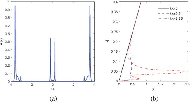
Figure 4. The position dependent absorption (a)A(kx) and (b) the OB curve (xversusy) for different positions of localized atoms. Parameters used are, R1 = R2 = 0.5γ, Rm = 10γ, Δm = Δ1 = Δ2 = 0,
Δp = 0.001γ, k1 = 0.9k, k2 = k, φ= 0, (a) Rp = 0.01γ, (b) C = 200, kx = 0 (solid), 0.21 (dashed),
3.59 (dash-dotted).
The effect of the standing wave on the Fabry-Perot cavity has been investigated [16]. Moreover, atom localization of different systems via absorption spectrum has been studied [17, 18]. We choose the required spatial-field arrangement for E1 and E2 to establish the standing wave along the direction
x, which is perpendicular to the probe propagation direction. Then, it is necessary to redefine the space dependent Rabi frequencies as Ω1(x) =R1sin(k1x+φ) and Ω2(x) =R2sin(k2x),whereki is the
magnitude of wave vector of field Ei, andφ stands for spatial phase shift of two fields. Therefore, the optical properties of the system depend on the transverse position of localized atoms, and then OB behavior can be controlled by position atoms, intensity and phase shift of standing wave.
In Fig. 4, we plot the position dependent absorption (a)A(kx) and (b) the OB curve for different positions of localized atoms. Parameters used are R1 = R2 = 0.5γ, Rm = 10γ, Δp = 0.001γ,
Δm = Δ1 = Δ2 = 0, k1 = 0.9k, k2 = k, φ = 0, (a) Rp = 0.01γ, (b) C = 200, kx = 0 (solid),
does not show bistable behavior. The atoms located aroundkx= 0.21 show bistable behavior (dashed), while OM behavior is induced by atoms located aroundkx= 3.59 of standing wave (dash-dotted). Then OB and OM behaviors of the system can be controlled by simple shift of the standing wave cavity inx direction.
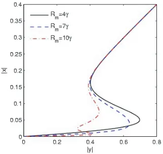
Now, we are interested in studying the effect of microwave field on OB behavior of the system. In Fig. 5, we plot OB behavior of the system for different values of microwave intensities. Parameters used are C = 200, kx= 0.21, Rm = 4γ (solid), Rm = 7γ (dashed), Rm = 10γ (dash-dotted). Other parameters are the same as in Fig. 4(a). Fig. 5 shows that the threshold value and hysteresis cycle width of the bistable curve are reduced by increasing the microwave field intensity.
The effect of the intensity of the standing wave on the OB behavior of the system is shown in Fig. 6. We assume that the driving fields E1, E2 and Em are exactly tuned to the corresponding transitions,
and the phase-shift φis set as zero. The input-output curve is plotted for different values of intensity of the driving fields. Used parameters are kx = 0.21, R1 = R2 = R = 0.1γ (dotted), 0.5γ (dashed),
5 (solid). Other parameters are the same as in Fig. 4. We find that OB behavior can be induced to the system by increasing the intensity of standing waves. It is worth noting that the optical properties
Figure 5. The OB behavior for different microwave field intensities. Parameters used are kx = 0.21, Rm = 4 (solid), Rm = 7 (dashed), Rm = 10 (dash-dotted). Other parameters are same as in Fig. 4.
Figure 6. The input-output curve for different values of intensity of the driving standing fields. Used parameters are kx = 0.21, R1 =R2 =R =
0.1γ (solid), 0.4γ (dashed), 0.8γ (dash-dotted). Other parameters are same as in Fig. 4.
Figure 7. The input-output curve of the system for different values of phase-shift. Selected parameters are R1 = 0.1γ, R2 = 0.5γ, Rm = 10γ, k2 = k, k1 = 0.9k, kx = 1.5, φ = 0 (solid), 2 (dashed), 3
of the system depend also on the phase-shift of applied fields. The input-output curves of the system, for different values of phase-shift, are plotted in Fig. 7. Selected parameters areR1 = 0.1γ,R2= 0.5γ,
Rm = 10γ, kx = 1.5 , φ = 0 (solid), 2 (dashed), 3 (dash-dotted). Other parameters are the same as
in Fig. 4. It is seen that OB of the system switches to OM just by changing the phase-shift of applied fields. The physical origin lies on the fact that the position of the absorption peaks depends on the phase shift between the two considered standing waves.
Finally, we are going to determine the stable and unstable branches in OM diagrams which are important in all-optical multistate switching or coding elements [19]. Fig. 8 shows the stable (solid) and unstable (dotted) branches in four different OM curves which are selected from Fig. 3(a), Fig. 5(b), Fig. 6(c) and Fig. 7(d). The input-output solutions show two S-type curves, which gives rise to the tristability in certain input intensity region. The jump up and jump down output intensities are shown by dashed arrows.
(a) (b)
(c) (d)
Figure 8. The stable (solid) and unstable (dotted) branches in four different OM curves which are selected from Fig. 3(a), Fig. 5(b), Fig. 6(c) and Fig. 7(d). The jump up and jump down output intensities are shown by dashed arrows.
4. CONCLUSION
REFERENCES
1. Lugiato, L. A., “Theory of optical bistability” Progress in Optics, E. Wolf, Ed., Vol. 21, North-Holland, Amesterdam, 1984.
2. Chrostowski, J., C. Delisle, and T. Tremblay, “Oscillations in an acoustooptic bistable device,” Can. J. Phys., Vol. 61, 188–191, 1983.
3. Balakshii, V. I., A. V. Kazar’yan, and A. A. Lee, “Multistability in an acousto-optical system with a frequency feedback,”Quantum Electronics, Vol. 25, No. 10, 940–944, 1995.
4. Ghosh, A. K., P. Verma, S. Cheng, R. C. Huck, M. R. Chatterjee, and M. Al-Saedi, “Design of acousto-optic chaos based secure free-space optical communication links,”Proc. of SPIE, Vol. 7464, 74640L, 2009.
5. Abraham, E. and S. D. Smith, “Optical bistability and related devices,”Rep. Prog. Phys., Vol. 45, 815, 1982.
6. Dawes, A. M. C., L. Illing, S. M. Clark, and D. J. Gauthier, “All-optical switching in rubidium vapor,”Science, Vol. 308, 672, 2005.
7. Rosenberger, A. T., L. A. Orozco, and H. J. Kimble, “Observation of absorptive bistability with two-level atoms in a ring cavity,” Phys. Rev. A, Vol. 28, 2569, 1983.
8. Anton, M. A. and O. G. Calderon, “Optical bistability using quantum interference in V-type atoms,” J. Opt. B: Quantum Semiclass. Opt., Vol. 4, 91–98, 2002.
9. Joshi, A., W. Yang, and M. Xiao, “Effect of quantum interference on optical bistability in the three-level V-type atomic system,”Phys. Rev. A, Vol. 68, 015806, 2003.
10. Mousavi, S. M., L. Safari, M. Mahmoudi, and M. Sahrai, “Effect of quantum interference on the optical properties of a three-level V-type atomic system beyond the two-photon resonance condition,”J. Phys. B: At. Mol. Opt. Phys., Vol. 43, 165501, 2010.
11. Feng, Z. F., W. D. Li, L. T. Xiao, and S. T. Jia, “The double dark resonance in a cold gas of Cs atoms and molecules,”Opt. Exp., Vol. 16, 15870, 2008.
12. Mahmoudi, M., S. M. Mousavi, and M. Sahrai, “Controlling theoptical bistability via interacting dark-state resonances,” EPJD, Vol. 57, 241–246, 2010.
13. Vafafard, A., H. Zaakeri, L. E. Zohravi, and M. Mahmoudi, “Phase-controlled optical bistability via electromagnetically induced absorption,” JOSA B, Vol. 31, 1981, 2014.
14. Dutta, B. K., “Coherent control of narrow structures in absorption, transparency and dispersion by interference induced among the Rabi-split resonances,”Phys. Lett. A, Vol. 377, 1890, 2013. 15. Scully, M. O. and M. S. Zubairy,Quantum Optics, Cambridge University Press, London, 1997. 16. McCALL, S. L. and H. M. GIBBS, “Standing wave effects in optical bistability,” Opt. Commun.,
Vol. 33, 335, 1980.
17. Qamar, S., S. Y. Zhu, and M. S. Zubairy, “Precision localization of single atom using Autler-Townes microscopy,” Opt. Commun., Vol. 176, 409, 2000.
18. Sahrai, M., M. Mahmoudi, and R. Kheradmand, “Atom localization of a two-level pump-probe system via the absorption spectrum,”Laser Phys., Vol. 17, 40, 2007.