Utilization of Low Computational Cost Two Dimensional Analytical
Equations in Optimization of Multi Rings Permanent
Magnet Thrust Bearings
Siddappa I. Bekinal1, *, Mrityunjay Doddamani2, and Nikhil D. Dravid1
Abstract—Replacement of conventional bearings by passive magnetic bearings for high-speed applications, in terms of their performance will be effective, if the design is carried out by optimizing the geometrical dimensions in the given control volume. Present work deals with modification and utilization of two-dimensional (2D) analytical equations in optimization of multi rings permanent magnet (PM) thrust bearing configurations. Conventional and rotational magnetized direction (RMD) configurations are selected in optimizing the design variables for maximum bearing characteristics in a given volume with a constant aspect ratio. The design variables chosen for optimization are axial offset of rotor, number of rings, radial air thickness and inner diameter of the rotor and stator PM rings. MATLAB codes for solving 2D equations are developed in optimizing configuration variables. Further, optimized parameter values of the two configurations are compared. Finally, optimized results obtained using 2D and three-dimensional (3D) equations for the conventional configuration with same aspect ratio are compared, and conclusions are presented.
1. INTRODUCTION
PM bearings are the devices wherein shaft rotate without any contact with the support owing to magnetic force generated between permanent magnets. PM bearings are obtained by either axially or radially magnetized PM rings or combinations thereof [1, 2]. The features of bearings that are made of only two rings are smaller. It can be improved by using layers of rings, which can be stacked with a definite magnetization pattern. The axially and/or radially polarized ring magnets can be stacked in a specific pattern to obtain conventional, perpendicular, or Halbach magnetized configurations [3]. Such stackings increase the force and stiffness to a great extent. According to Earnshaw’s theorem [4], complete passive magnetic levitation is not possible and stable equilibrium cannot be achieved. Thereby, at least one degree of freedom has to be controlled by some other means. Even then, these types of bearings are quite attractive and due to their advantages these have been used extensively in various applications like wind turbines, flywheel systems, ventricular assist device and spacecraft applications [5–7]. Tian et al. [8] have developed 2D analytical equations for axial and radial force in conventional and rotational magnetized stack structured PM bearings made up of ‘n’ number of ring pairs. Three dimensional equations for bearing features in multi rings PM bearings having possible kinds of polarization rings is presented by Bekinal and Jana [9] to overcome the curvature effect which is neglected in developing 2D equations. Increased utilization of PM bearing in different applications necessitates optimization of bearing characteristics and which is achieved by considering the effect of various parameters such as magnet volume, number of rings on rotor and stator, axial position of the
Received 20 July 2017, Accepted 25 September 2017, Scheduled 8 November 2017 * Corresponding author: Siddappa I. Bekinal ([email protected]).
rotor, radial air thickness, magnetization pattern and geometrical parameters. Analytical and/or FEA techniques can be used for optimization. Conventional multi rings radial passive magnetic bearing is optimized by Moser et al. [10] for maximum radial stiffness using 2D FEA. Yoo et al. [11] optimized non-contact thrust bearings for maximum axial force using 2D equations. Lijesh and Hirani [12] optimized radial passive magnetic bearing with a single ring pair using modified 2D equations. Bekinal et al. [13] presented the effectiveness of optimization in conventional multi rings thrust bearing using 3D equations in a given space for maximum bearing features. Recently, Beneden et al. [14] carried out the optimization for all possible kinds of multi rings PM thrust bearing for maximum bearing characteristics using 2D equations.
The observations made out of the prevailing literature on optimization of stack structured PMB are,
• In Refs. [11, 14], optimization is carried out by considering equal radial ring thickness ((R2−R1) = (R4−R3)) leading to partial optimization.
• 2D FEA technique is used to carry out optimization of conventional radial bearing in Ref. [10].
• Optimization of perpendicularly magnetized multi rings passive magnetic thrust bearing has not been carried out so far to the best of authors knowledge in a given control volume.
• Computational time for solving 3D equations as against 2D equations is quite high.
• 2D analytical equations for force in PM bearings with n rings have not been explored yet in optimization.
These observations necessitate the authors to carry out the complete optimization of conventional and rotational magnetized stack structured PM thrust bearings using 2D analytical equations.
In this work, the 2D analytical equations developed by Tian et al. [8] using Coulombian approach have been modified for ‘n’ ring pairs and optimization has been carried out for maximum bearing features in axially and perpendicularly polarized multi rings PM thrust bearings. Both configurations are optimized for the aspect ratio of 0.5. Presented equations are solved in MATLAB in carrying out the optimization process. The procedure for optimizing different geometrical parameters in both the configurations in a given control volume is presented with elaborate discussion.
2. ANALYTICAL EQUATIONS FOR FORCE AND STIFFNESS 2.1. Permanent Magnet Thrust Bearing Configurations
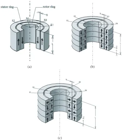
Stack structured PM thrust bearings are realised using three types of ring magnets: axial, radial and/or perpendicular magnetization. As the stack structured bearings with only axially or radially polarized magnets exhibit similar bearing performance characteristics, two configurations: conventional and RMD are chosen for the optimization study. The thrust bearing configuration with one pair of axially magnetized rings and ‘n’ number of axially as well as radially polarized ring pairs in the same cylindrical volume is presented in Fig. 1.
Analytical equations of axial force generated between two rings of PM bearings suggested by Tian et al. [8] are presented in Equations (1) and (2). The equations are based on 2D plane model, and detailed parameters used are shown in Fig. 2. In 2D plane model, the force exerted between two long parallel magnets is calculated with the help of their cross-section areas as shown in Fig. 2(a). The geometrical dimensions of cross sections of two rings inXZ plane are shown Fig. 2(b). The force exerted between two axially/radially polarized rings and between two perpendicularly polarized rings is obtained by considering two cases (I and II), and modified equations of axial force in multi-rings PM bearings are also presented thereafter.
Case I (For axially or radially magnetized ring pairs): Whenβ1+β2= 0, 2π and β1+β2 =π, the
axial forceFz inz-direction can be expressed as,
Fz =±Br1Br2L×10 −6
4πμ0
(a) (b)
(c)
Figure 1. PM thrust bearing configuration with (a) axially magnetized one ring pair, (b) axially magnetized multi ring pairs (conventional structure) and (c) perpendicularly magnetized multi ring pairs (RMD structure).
where, when β1+β2 =π, take ‘+’ symbol, and whenβ1+β2 = 0, 2π, take ‘−’ symbol. ϕ(k) = (t−p) ln(c−p)2+ (q+w)2−2tlnt2+ (q+w)2
+ (t+p) ln
(t+p)2+ (s+w)2
−(t+p) ln
(t+p)2+ (q+t+w)2
−(t+p) ln
(t+p)2+w2
+ (t+p) ln
(t+p)2+ (q+w)2
+ (t−p) ln
(t−p)2+ (s+w)2
−2tln
t2+ (s+w)2
−(t−p) ln
(t−p)2+ (q+s+w)2
+ 2tln
t2+ (q+s+w)2
−(t−p) ln
(t−p)2+w2
S1 S2 J1 J2
r
uv β3 β4 θ X Zo
Y U vx
z
o
p
q
t(p+g)
s
w
p
U Vr
uv (a) (b)Figure 2. Details of 2D plane model (a) cross sections of two long parallel magnets, (b) geometrical dimensions of cross sectional areas of two long magnets in XZ plane [8].
+2 (s+w)
arctan t−p
s+w
+ arctan t+p
s+w
−2 arctan t
s+w
+2 (q+w)
arctan t−p
q+w
+ arctan t+p
q+w
−2 arctan t
q+w
−2h
arctan t−p
w
+ arctan t+p
w
−2 arctan t
w
+2 (q+s+w)
2 arctan t
q+s+w
−arctan t+p
q+s+w
−arctan t−p
q+s+w
Case II (For perpendicularly magnetized ring pairs): Whenβ1+β2=π/2 andβ1+β2 =−π/2,
Fz =±Br1Br2L×10 −6
4πμ0
φ(k) [8] (2)
where, when β1+β2 =−π/2, take ‘+’ symbol, and whenβ1+β2=π/2, take ‘−’ symbol.
φ(k) = 2 (s+w) ln
(t2+ (s+w)2
−2 (q+s+w) ln
(t2+ (q+s+w)2
−(s+w) ln
(t+p)2+ (s+w)2
+ (q+s+w) ln
(t+p)2+ (q+s+w)2
−(s+w) ln
(t−p)2+ (s+w)2
+ (q+s+w) ln
(t−p)2+ (q+s+w)2
−2hlnt2+w2
+wln
(t−p)2+w2
+ 2 (q+w) ln
t2+ (q+w)2
−(q+w) ln
(t−p)2+ (q+w)2
+wln
(t+p)2+w2
−(q+w) ln
(t+p)2+ (q+w)2
+4c
2 arctan s+w
t
−arctan q+s+w
t −arctan w t
−2 (t+p)
2 arctan s+w
t+p
−arctan q+s+w
t+p
−arctan w
t+p
−2 (t−p)
2 arctan s+w
t−p
−arctan q+s+w
t−p
−arctan w
t−p
2.2. Magnetic Force 2D Analytical Model for Conventional and RMD PM Thrust Bearings
Modified equations of force in multi-rings PM thrust bearing configurations are expressed as follows. For conventional configuration presented in Fig. 1(b),
Fz = Br1Br2L×10 −6
4πμ0
n
i=1
n
j=1
(−1)i+jϕ(kij) (3)
For RMD configuration shown in Fig. 1(c),
Fz = Br1Br2L×10 −6
4πμ0
n
i=1
n
j=1
Fij (4)
where,
Fij = (−1)i+j2 −iϕ(kij) for (i+j) is even
and Fij = (−1)i+j+12 −iφ(kij) for (i+j) is odd
kij =k+ (j−i)pis the axial distance of jth inner ring magnet toith outer ring magnet. Equations (3) and (4) are used to estimate magnetic thrust force between rotor and stator ring magnets in a given bearing configuration. The longitudinal length L can be approximated to the average length of a pair of magnetic rings.
The equation for axial stiffness generated in the stack structured configuration is given by the three-point midpoint formula,
Kz= dFz
dz =
1
2Δz[Fz(z+ Δz)−Fz(z−Δz)] (5)
3. OPTIMIZATION
Optimization of PM thrust bearings is carried out to compute maximum bearing features in a given space. Optimization process involves the variation of parameters of the bearing in addition to determining the parameters for maximum bearing features. Crucial parameters of the bearing affecting force and stiffness are axial position (z), number of ring pairs (n), ring axial height (h), radial air thickness (g), outer and inner radii of inner rings (R4 andR3), and outer and inner radii of outer rings (R2 andR1).
MATLAB codes are written to optimize each variable separately. The steps followed in the optimization process are:
(i) Firstly, for a particular air gap, R4 and L are fixed due to assumed cylindrical volume constant aspect ratio.
(ii) Then ‘n’ is increased, and axial force is calculated for various axial offset values (z). The values of number of ring pairs (n) and axial position (z) at which bearing features are maximum are the optimum values, i.e.,nopt and zopt.
(iii) Based on the optimum values (nopt and zopt), axial force is calculated for different values of inner
radius of stator ring (R3) by fixingR1. The value at which axial force is maximum is the optimum value, i.e.,R3opt.
(iv) Since the air gap (g) which is the difference betweenR2 andR3 is fixed, outer radius of rotor ring (R2) gets optimized along withR3.
(v) Using the optimized values, nopt, zopt and R3opt, R1 is varied. The value of R1 at which the
characteristics are maximum is the optimum value,R1opt.
Table 1. Parametric values of PM thrust bearing.
Parameter Value
Inner radius of rotor rings, R1 (mm) 9 Outer radius of rotor rings,R2 (mm) 14 Inner radius of stator rings,R3 (mm) 15 Outer radius of stator rings,R4 (mm) 20
Air gap,g(mm) 1
Axial length,L (mm) 20
Magnetic polarization,Br (T) 1.2
Aspect ratio AR=L/D4 0.5
-20 -15 -10 -5 0 5 10 15 20 -500
-400 -300 -200 -100 0 100 200 300 400 500
Axial offset z (mm)
Axi
al
F
or
ce F
z(N)
n=1 n=2 n=3
-30 -20 -10 0 10 20 30 -800
-600 -400 -200 0 200 400 600 800
Axial offset z (mm)
A
xia
l Fo
rc
e Fz
(N
)
n=2 n=3 n=4
(a) (b)
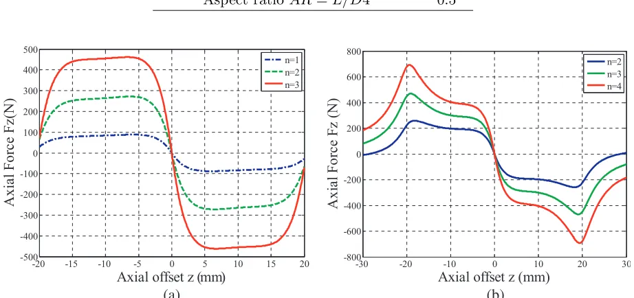
Figure 3. Axial force in stack structured PM thrust bearings with 1–3 ring pairs of the configuration with (a) axial and (b) perpendicular magnetization pattern.
The effect of axial position (z) of the rotor with respect to number of rings is demonstrated by increasing the rings on the rotor and stator from one to three with axial ring length of 20 mm. The change of axial force and stiffness with axial position are plotted in Figs. 3 and 4.
Figure 3(a) reveals that the axial force for axial magnetization pattern is maximum at an axial offset approximately equal to half the ring axial length. Fig. 3(b) shows that the maximum axial force for perpendicular magnetization pattern occurs at an axial offset approximately equal to the ring axial length. Figs. 4(a) and 4(b) depict that maximum axial stiffness occurs at zero axial offset for both axial and perpendicular magnetization patterns. From Figs. 3 and 4, the range of axial offset values within which force and stiffness are maximum is decided for both the configurations. The values of bearing features increase with increasing ring pairs.
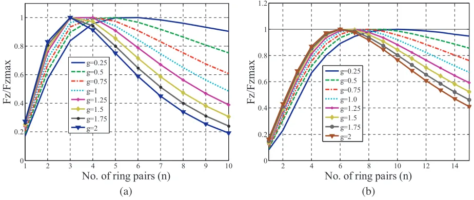
The values of other parameters such as n,g, R3 and R1 are calculated based on optimized value of an axial offset. Number of rings on the stator and rotor (n) is optimized for eight values of air gap (0.25 to 2 mm in increments of 0.25). Optimized values of n for different air gap values in axial and perpendicular magnetization patterns are presented in Figs. 5 and 6, and the optimized values are listed in Table 2.
Figures 5 and 6 indicate that the numbers of rings on the rotor and stator at which bearing characteristics are maximum, decreasing with increasing air gap for both axial and perpendicular magnetization patterns.
-20 -15 -10 -5 0 5 10 15 20 -2
-1.5 -1 -0.5 0 0.5 1 1.5 2 2.5x 10
5
Axial offset z (mm)
Ax
ia
l Stiff
ness
Kz(N/m)
n=1 n=2 n=3
-20 -15 -10 -5 0 5 10 15 20 -5
0 5 10 15 20x 10
4
Axial offset z (mm)
Ax
ia
l st
iffn
ess Kz
(N/
m
)
n=2 n=3 n=4
(a) (b)
Figure 4. Axial stiffness in stack structured PM thrust bearings with 1–3 ring pairs for selected configuration with (a) axial and (b) perpendicular magnetization pattern.
1 2 3 4 5 6 7 8 9 10
0 0.2 0.4 0.6 0.8 1
No. of ring pairs (n)
Fz
/F
zmax
g=0.25 g=0.5 g=0.75 g=1 g=1.25 g=1.5 g=1.75 g=2
2 4 6 8 10 12 14
0 0.2 0.4 0.6 0.8 1 1.2
No. of ring pairs (n)
Fz
/F
zmax g=0.25g=0.5 g=0.75 g=1.0 g=1.25 g=1.5 g=1.75 g=2
(a) (b)
Figure 5. Optimized values of n with respect to maximum axial force in (a) axial and (b) perpendicular magnetization configurations.
approximately doubles the number of ring pairs for axial magnetization pattern in the case of both axial force and stiffness.
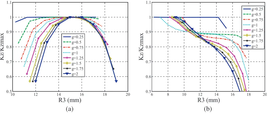
R3 is optimized by fixing R1 and nopt for different air gaps. Changes in the optimized values of R3 for different air gaps for maximum bearing features in both magnetizations are exhibited in Figs. 7 and 8.
Figure 7(a) shows that for maximum axial force in axial magnetization, the optimum value of R3 lies between 14 and 16 mm for all the air gaps. It shows a slight deviation for air gaps of 1 and 2 mm for which the values are 12 and 13 mm, respectively.
It is observed from Fig. 7(b) that the optimum value of R3 is almost same for all the air gaps and varies between 6 and 8 mm.
5 10 15 20 25 0
0.2 0.4 0.6 0.8 1
No. of ring pairs (n)
K
z/
K
zmax
g=0.25 g=0.5 g=0.75 g=1.0 g=1.25 g=1.5 g=1.75 g=2
5 10 15 20 25 30 35 40 45 50 55 0
0.2 0.4 0.6 0.8 1
No. of rings (n)
Kz/
K
zmax g=0.25 g=0.5 g=0.75 g=1 g=1.25 g=1.5 g=1.75 g=2
(a) (b)
Figure 6. Optimized values of n with respect to maximum axial stiffness in (a) axial and (b) perpendicular magnetization pattern.
8 10 12 14 16 18
0.4 0.5 0.6 0.7 0.8 0.9 1 1.1
R3 (mm)
Fz
/F
zm
ax
g=0.25 g=0.5 g=0.75 g=1 g=1.25 g=1.5 g=1.75 g=2
6 8 10 12 14 16 18
0 0.2 0.4 0.6 0.8 1
R3 (mm)
Fz
/F
zmax
g=0.25 g=0.5 g=0.75 g=1 g=1.25 g=1.5 g=1.75 g=2
(a) (b)
Figure 7. Change in the optimized values ofR3 for different air gaps for maximum axial force in (a) axial and (b) perpendicular magnetization pattern.
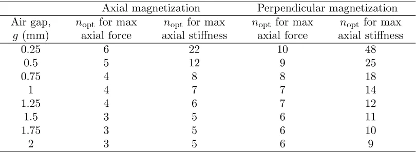
Table 2. Optimized values nfor maximum bearing features.
Axial magnetization Perpendicular magnetization Air gap,
g (mm)
nopt for max axial force
nopt for max axial stiffness
nopt for max axial force
nopt for max axial stiffness
0.25 6 22 10 48
0.5 5 12 9 25
0.75 4 8 8 18
1 4 7 7 14
1.25 4 6 7 12
1.5 3 5 6 11
1.75 3 5 6 10
10 12 14 16 18 20 0.5
0.6 0.7 0.8 0.9 1 1.1
R3 (mm)
Kz/Kz
ma
x g=0.25
g=0.5 g=0.75 g=1 g=1.25 g=1.5 g=1.75 g=2
6 8 10 12 14 16 18 20 0.5
0.6 0.7 0.8 0.9 1 1.1
R3 (mm)
Kz/Kzma
x
g=0.25 g=0.5 g=0.75 g=1 g=1.25 g=1.5 g=1.75 g=2
(a) (b)
Figure 8. Change in the optimized values of R3 for different air gaps for maximum axial stiffness in (a) axial and (b) perpendicular magnetization pattern.
2 4 6 8 10 12
0 0.2 0.4 0.6 0.8 1
R1 (mm)
Fz
/F
zmax
g=0.25 g=0.5 g=0.75 g=1 g=1.25 g=1.5 g=1.75 g=2
1 2 3 4 5 6 7
0 0.2 0.4 0.6 0.8 1
R1 (mm)
Fz
/F
zmax
g=0.25 g=0.5 g=0.75 g=1 g=1.25 g=1.5 g=1.75 g=2
(a) (b)
Figure 9. Change in the optimized values of R1 for different air gap values for maximum axial force in (a) axial and (b) perpendicular magnetization pattern.
Figure 8(b) shows the optimized values of R3 for maximum axial stiffness in perpendicular magnetization which varies from 6 to 9 mm.
R1 is optimized usingzopt,nopt and R3opt. The change in the optimized values ofR1 for different
air gaps for maximum bearing features in axial and perpendicular magnetization patterns are depicted by Figs. 9 and 10.
Figures 9(a) and (b) show that maximum axial force for all the air gaps in both axial and perpendicular magnetization patterns remains unaffected for a range of values of R1 up to a certain critical value and decreases suddenly thereafter.
Figures 10(a) and (b) show that the optimum values ofR1 for maximum axial stiffness in axial and perpendicular magnetization are in the ranges of 9–12 and 5–8 mm, respectively for various air gaps.
2 4 6 8 10 12 0.2
0.3 0.4 0.5 0.6 0.7 0.8 0.9 1 1.1
R1 (mm)
K
z/
K
zmax g=0.25g=0.5 g=0.75 g=1 g=1.25 g=1.5 g=1.75 g=2
1 2 3 4 5 6 7 8 9 10 0.7
0.75 0.8 0.85 0.9 0.95 1 1.05 1.1
R1 (mm)
Kz/
K
zmax
g=0.25 g=0.5 g=0.75 g=1 g=1.25 g=1.5 g=1.75 g=2
(a) (b)
Figure 10. Change in the optimized values ofR1 for different air gaps for maximum axial stiffness in (a) axial and (b) perpendicular magnetization.
Table 3. Optimized values of geometrical parameters of PM thrust bearings.
Parameters
Conventional Configuration RMD Configuration
For Max. Axial Force
For Max. Axial stiffness
For Max. Axial force
For Max. Axial stiffness
n 4 7 7 14
zopt (mm) −2.6 0 −2.8 0
hopt (mm) 5 2.857 2.857 1.428
L (mm) 20 20 20 20
R4 (mm) 20 20 20 20
R3opt (mm) 12 15 8 7
R2opt (mm) 11 14 7 6
R1opt (mm) 1 10 4 5
412.1107 N 333930 N/m 935.1197 N 701750 N/m
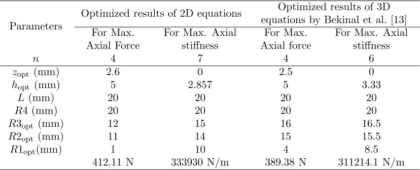
Table 4. Comparison of optimized results obtained using 2D and 3D equations.
Parameters
Optimized results of 2D equations Optimized results of 3D equations by Bekinal et al. [13] For Max.
Axial Force
For Max. Axial stiffness
For Max. Axial force
For Max. Axial stiffness
n 4 7 4 6
zopt (mm) 2.6 0 2.5 0
hopt (mm) 5 2.857 5 3.33
L (mm) 20 20 20 20
R4 (mm) 20 20 20 20
R3opt (mm) 12 15 16 16.5
R2opt (mm) 11 14 15 15.5
R1opt(mm) 1 10 4 8.5
-20 -15 -10 -5 0 5 10 15 20 -400
-300 -200 -100 0 100 200 300 400
Axial offset z (mm)
Ax
ialF
orce
F
z(
N
)
n=1 n=4
-20 -15 -10 -5 0 5 10 15 20 -4
-3 -2 -1 0 1 2 3 4x 10
5
Axial offset z (mm)
A
xia
l Stiff
ne
ss
K
z(N/
m
)
n=1 n=7
(a) (b)
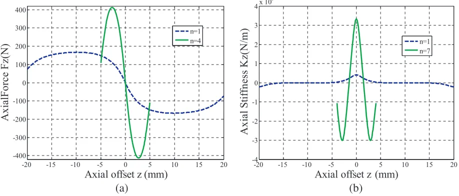
Figure 11. Maximized characteristics of conventional PM thrust bearing configuration with optimized number of ring pairs along with one ring pair on the rotor for 1 mm air gap for (a) axial force and (b) stiffness.
-20 -15 -10 -5 0 5 10 15 20 -1000
-800 -600 -400 -200 0 200 400 600 800 1000
Axial offset z (mm)
A
xia
l Fo
rc
e Fz
(N)
n=7 n=2
-5 0 5
-8 -6 -4 -2 0 2 4 6 8x 10
5
Axial offset z (mm)
Ax
ial Stiffn
ess
Kz (N
/m
)
n=14 n=2
(a) (b)
Figure 12. Maximized characteristics of RMD thrust bearing configuration with optimized number of ring pairs along with two ring pairs on the rotor for 1 mm air gap for (a) axial force and (b) stiffness.
Figures 11(a) and (b) compare the maximized bearing characteristics of conventional PM thrust bearing configuration with one ring pair and optimum number of ring pairs for 1 mm air gap. Figures 12(a) and (b) present maximized characteristics values for perpendicularly magnetized PM thrust bearing configuration with two ring pairs and optimum number of ring pairs for 1 mm air gap.
4. COMPARISON OF OPTIMIZED RESULTS OBTAINED USING 2D AND 3D EQUATIONS
The proposed optimized results of the conventional configuration using 2D analytical equations are compared with the optimized results available in the literature [13]. In [13], optimization was carried out using 3D equations for the same aspect ratio of the configuration. Comparison results for the conventional configuration are presented in Table 4. Slight deviation in the results (5.8% with respect to force and 7.3% with respect to stiffness) is noticed, due to the negligence of curvature effect in deriving 2D analytical equations. Variation in the optimized results of design variables is also observed.
5. CONCLUSION
Optimization of axially and perpendicularly polarized multi-rings PM thrust bearings is carried out using 2D analytical equations. It is observed that the force and stiffness increase significantly (2.5 and 8.1 times) for a bearing with aspect ratio 0.5 having 1 mm air gap in the optimized conventional configuration as compared to a single ring pair in the same control volume. The force and stiffness increase further if perpendicular magnetization pattern is used (approximately 2 times of the axial magnetisation pattern). Increase in the value of optimum number of ring pairs (4 to 7 for maximum force and 7 to 14 for maximum axial stiffness) is observed in perpendicularly polarized pattern compared to axial magnetization pattern for the same aspect ratio. Finally, the optimized results obtained using 2D and 3D equations for the same bearing configuration are compared, and suitability of 2D equations is presented. The designers of PM thrust bearing can use 2D analytical equations easily in order to carry out the optimization with low computational cost.
6. NOMENCLATURE
J1 and J2 Magnetization residual magnetism induction density vectors, Tesla
Br1 and Br2 Components of the magnetization residual magnetism induction density vectors,
Tesla
β1 andβ2 Angles made by Br1 and Br2 with theX-axis, degree
R1 Inner radius of rotor rings, mm
R2 Outer radius of rotor rings, mm
R3 Inner radius of stator rings, mm
R4 Outer radius of stator rings, mm
g Air gap, mm
L Axial length, mm
AR Aspect ratio =L/D4
h Axial length of each ring, mm
n Number of rings on rotor and stator
z axial offset, mm
p(R2−R1)×q(h) Cross section of rotor rings, mm2
p(R4−R3)×s(h) Cross section of stator rings, mm2
ACKNOWLEDGMENT
REFERENCES
1. Bekinal, S. I., T. R. Anil, and S. Jana, “Analysis of axially magnetized permanent magnet bearing characteristics,” Progress In Electromagnetics Research B, Vol. 44, 327–343, 2012.
2. Bekinal, S. I., T. R. Anil, S. Jana, S. S. Kulkarni, A. Sawant, N. Patil, and S. Dhond, “Permanent magnet thrust bearing: Theoretical and experimental results,” Progress In Electromagnetics Research B, Vol. 56, 269–287, 2013.
3. Ravaud, R. and G. Lemarquand, “Halbach structures for permanent magnets bearings,” Progress In Electromagnetic Research M, Vol. 14, 263–277, 2010.
4. Earnshaw, S., “On the nature of the molecular forces which regulate the constitution of the luminiferous ether,” Transactions of the Cambridge Philosophical Society, Vol. 7, 97–112, 1842. 5. Sotelo, G. G., R. Andrade, and A. C. Ferreira, “Magnetic bearing sets for a flywheel system,”IEEE
Trans. on Applied Super Conductivity, Vol. 17, No. 2, 2150–2153, 2007.
6. Fang, J., Y. Le, J. Sun, and K. Wang, “Analysis and design of passive magnetic bearing and damping system for high-speed compressor,”IEEE Trans. Magn., Vol. 48, No. 9, 2528–2537, 2012. 7. Morales, W., R. Fusaro, and A. Kascak, “Permanent magnetic bearing for spacecraft applications,”
Tribology Transactions, Vol. 46, No. 3, 460–464, 2003.
8. Tian, L.-L., X.-P. Ai, and Y.-Q. Tian, “Analytical model of magnetic force for axial stack permanent-magnet bearings,” IEEE Trans. Magn., Vol. 48, No. 10, 2592–2599, 2012.
9. Bekinal, S. I. and S. Jana, “Generalized three-dimensional mathematical models for force and stiffness in axially, radially, and perpendicularly magnetized passive magnetic bearings with ‘n’ number of ring pairs,” ASME Journal of Tribology, Vol. 138, No. 3, 031105(1–9). 2016.
10. Moser, R., J. Sandtner, and H. Bleuler, “Optimization of repulsive passive magnetic bearings,”
IEEE Trans. Magn., Vol. 42, No. 8, 2038–2042, 2006.
11. Yoo, S. Y., et al., “Optimal design of non-contact thrust bearing using permanent magnet rings,”
Int. Journal of Precision Engg. and Manufacturing, Vol. 12, No. 6, 1009–1014, 2011.
12. Lijesh, K. P. and H. Hirani, “Development of analytical equations for design and optimization of axially polarised radial passive magnetic bearing,”ASME Journal of Tribology, Vol. 137, 011103(1– 9), 2015.
13. Bekinal, S. I., M. R. Doddamani, and S. Jana, “Optimization of axially magnetised stack structured permanent magnet thrust bearing using three dimensional mathematical model,” ASME Journal of Tribology, Vol. 139, No. 3, 031101(1–9), 2017.
![Figure 2. Details of 2D plane model (a) cross sections of two long parallel magnets, (b) geometricaldimensions of cross sectional areas of two long magnets in XZ plane [8].](https://thumb-us.123doks.com/thumbv2/123dok_us/1978862.1261401/4.612.116.504.83.271/figure-details-sections-parallel-magnets-geometricaldimensions-sectional-magnets.webp)