I
CARD
UTILITY
PRDGRAMS
I I
I I
This manual is published by the Univac Division of Sperry Rand Corporation in loose leaf format. This format provides a rapid and complete means of keeping recipients apprised of UNIV AC @ Systems developments. The infor-mation presented herein may not reflect the current status of the product. For the current status of the product, contact your local Univac Represent-ative.
The Univac Division will issue updating packages, utilizing primarily a page-for-page or unit replacement technique. Such issuance will provide notification of hardware or software changes and refinements. The Univac Division reserves the right to make such additions, corrections, and/or deletions as, in the judgment of the Univac Division, are required by the development of its Systems.
UNIVAC is a registered trademark of Sperry Rand Corporation.
UP-4120 " Rev. 2
I I ,
CONTENTS
UNIVAC 9200/9200 11/9300/9300 II
CARD UTILITY PROGRAMS
1. INTRODUCTION
1.1.
GENERAL1.2.
MACRO INSTRUCTIONS1.2.1.
Declarative Macro Instructions1.2.2.
Imperative Macro Instructions1.3.
STATEMENT CONVENTIONS2. MULTI PLY/DIVIDE AND EDIT SUBROUTINES
2.1.
GENERAL2.2.
MULTIPLY/DIVIDE SUBROUTINE2.2.1.
Instruction Format2.2.2.
Timing Formulas for Multiply/Divide Subroutine2.3.
EDIT SUBROUTINE2.3.1.
Timing Formula for Edit Subroutine2.4.
HARDWARE COMPATIBILITY3. STERLING CONVERSION ROUTINES
3.1.
GENERAL 3.1.1. Format lA3.1.2.
Format1
B3.1.3.
Format2
3.1.3.1.
Shillings3.1.3.2.
Pence3.1.3.3.
Format2
Types3.1.3.4.
Signs3.1.3.5.
Leading Zeros3.1.4.
Pence Format3.2.
CONVERSION ROUTINES3.3. USING CONVERSION ROUTINES
3.3.1.
Common Work Area3.3.2.
Converting Data3.4.
INCLUSION OF ROUTINES INTO THE PROBLEM PROGRAM3.4.1.
Joint Assembly3.4.2.
Separate AssemblyContents SECTION:
CONTENTS
1 to 3
1-1
to
1-2
1-1
1-1
1-2
1-2
1-2
2-1
to
2-5
2-1
2-1
2-2
2-3
2-4
2-5
2-5
3-1
to3-9
UP-4120
Rev. 2
UNIVAC 9200/9200 11/9300/9300 II
CARD UTILITY PROGRAMS
4. MEMORY DUMP ROUTINE
4.1.
GENERAL4.2. CONTENTS OF CONTROL AREA 4.3. PRINT FORMAT
4.4. MAIN STORAGE REQU IREMENTS
4.5. CHARACTERISTICS OF CLOSED SUBROUTINE FORM OF MEMORY ROUTINE
4.5.1. Memory-Dump-Subroutine (MDSBR) Declarative Macro Instruction 4.5.2. END Imperative Macro Instruction
4.5;3. Instructions Required for Execution of Closed Subroutine
4.6. CHARACTERISTICS OF SELF-LOADING FORM OF MEMORY DUMP ROUTIN E
4.6.1. Memory-Dump-Self-Loading-Form (MDSLF) Declarative Macro Instruction 4.6.2. END Imperative Macro Instruction
4.6.3. Programming Considerations 4.6.4. Operating Instructions
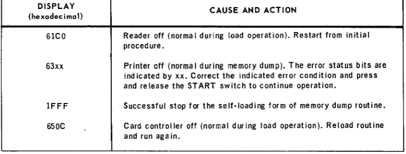
4.6.5.
Display stops5. SNAPSHOT ROUTINE
5.1. GEN ERAL
5.2. MAIN STORAGE REQUIREMENTS
5.3.
SNAP DECLARATIVE MACRO INSTRUCTIONS5.4. INSTRUCTIONS REQUIRED FOR ENTERING SNAPSHOT ROUTINE 5.4.1. Branch-and-Link (BAL) Instruction
5.4.2. Define-Constant (DC) Statement
5.5.
REQUIREMENTS FOR PRINTING SNAPSHOT DUMP 5.5.1. Print Format of Snapshot Dump6. SQUEEZE PROGRAM
6.1. GENERAL 6.2. CARD INPUT 6.2.1. START Card 6.2.2. Replace (R EP) Card 6.2.3. END Card
6.3.
OUTPUT 6.3.1. Text Card 6.3.2. Transfer Card 6.3.3. Print OutputContents
SECTION:
I
4-1 to 4-15 4-1 4-2 4-2 4-3 4-4 4-4 4-6 4-6
4-8
4-8
4-12 4-12 4-13 4-155-1 to 5-4 5-1 5-1 5-2 5-2
5-3
5-3
5-3 5-46-1
to6-13
UP-4120
Rev. 2
UNIVAC 9200/9200 11/9300/9300 II
CARD UTILITY PROGRAMS
6.4. LINKING SQUEEZE PROGRAM MODULES 6.4.1. Phase Control Card
6.4.2. External Definition (EQU) Cards 6.4.3. Arrangement of Modules in Input Deck 6.4.3.1. Card Load Routine
6.4.3.2. Squeez e Modu Ie 6.4.3.3. EXEC I
6.4.3.4. Card Read Routine 6.4.3.5. Card Punch Routine 6.4.3.6. Print Routine 6.4.4. END Control Card
6.5. OPERATING INSTRUCTIONS
7. SYMBOLIC LIST PROGRAM
7.1. G EN ERAL
7.2. PROGRAM REQUIREMENTS
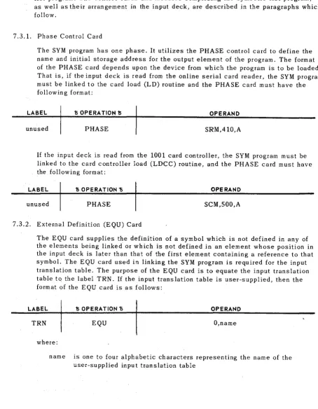
7.3. LINKING SYMBOLIC LIST PROGRAM 7.3.1. Phase Control Card
7.3.2. External Definition (EQU) Card 7.3.3. Arrangement of Modu les in Input Deck 7.3.3.1. Card Load Routine
7.3.3.2. SY M Modu Ie 7.3.3.3. EXEC I
7.3.3.4. Ca rd Read Routine 7.3.3.5. Print Routine 7.3.4. END Control Card
7.4. OPERATING INSTRUCTIONS FOR USING THE SYM PROGRAM
APPENDIX
A. STANDARD-CARD, EBCDIC, AND PRINTER-GRAPHIC CODES
FIGURES Contents SECTION: 6-5 6-5 6-6 6-6 6-6 6-6 6-7 6-7 6-9
6-11
6-13 6-,137-1 to 7-7
7-1 7-1 7-2 7-2 7-2 7-3 7-3 7-3 7-3 7-3 7-5 7-7 7-7
A-I to A-4
3-1. Linking Sequence, Format 2A to Format IB 3-7
3-2. Coding the Problem Program for Separate Assembly of the Sterling Routines 3-9
TABLES
3-1. Sterling Notation Format 3-2'
3-2. Maximum Sizes of Sterling Notation Formats 3-3
3-3. Sterling Amounts Expressed in Avai lab Ie Formats of Notation 3-3
3-4. Summary of Sterling Notation Formats 3-5
3-5. Conversion Routines 3-6
4-1. Display stops 4-15
3
UP-4120 Rev. 2
UNIVAC 9200/9200 11/9300/9300 II
CARD UTILITY PROGRAMS
SECTION.1
1. INTRODUCTION
1.1. GENERAL
The purpose of this manual is to describe the card utility programs supplied as part of the software package provided with the UNIVAC 9200/9200 11/9300/9300 II Card Systems. Descriptions of the macro instructions used to initiate and generate these utility routines and programs as well as descriptions of the displays resulting from or associated with the routines and programs are also included.
A knowledge of the UNIVAC 9200/9200 ll/9300/9300 II Systems Central Processor and Peripherals Programmers Reference, UP-7546 (current version) and the UNIVAC 9200/9200 1l/9300/9300 II Systems Card Assembler Programmers Reference, UP-4092 (current version) is helpful in using this manual.
Section 1 of this manual defines the declarative and imperative macro instructions and their parameters as used in this manual. A description of the statement conven-tions used to illustrate the statements in this manual is also provided in this section. The remainder of the manual is arranged as follows:
• Section 2 contains information pertaining to multiply/divide and edit subroutines. • Section 3 contains information pertaining to sterling conversion routines.
• Section 4 contains information pertaining to the memory dump routine. • Section 5 contains information pertaining to the snapshot dump routine. • Section 6 contains information pertaining to the squeeze program. • Section 7 contains information pertaining to the symbolic list program. 1.2. MACRO INSTRUCTIONS
A macro instruction is similar in format to a source code instruction. It mayor may not contain an entry in the label field, but it must contain an operation code in the operation field and one or more parameters in the operand field. The macro tions described in this document are classified as either declarative macro tions or imperative macro instructions. The declarative and imperative macro instruc-tions differ in three aspects: the purpose for which they are used, the format of the parameters specified in their operand fields, and the type of coding they generate.
1
UP-4120 Rev. 2
UNIVAC 9200/9200 11/9300/9300 II
CARD UTILITY PROGRAMS
1.2.1. Declarative Macro Instructions
1
SECTION:
Declarative macro instructions used keyword parameters to describe all the aspects of the file to be processed by the system. These aspects include parameters, con-stants, storage areas, special conditions, status, and options. Essentially, the declarative macro instruction defines each file required by the problem program. The code generated by the declarative macro instruction is nonexecutable and therefore should be separated from the inline file processing code.
The term "keyword parameter" refers to parameters which can be written in any order within the operand field. Keyword parameters must be separated by commas,
PAGE:
but it is not required that the omission of a keyword be indicated. Keyword parameters are recognizable by their format, which consists of a word or code immediately fol-lowed by an equals sign, which is in turn folfol-lowed by one specification.
1.2.2. Imperative Macro Instructions
Imperative macro instructions are used to point to the files described by the de-clarative macro instructions. In addition, imperative macro instructions are also used in providing additional details specifying the processing action to be taken. When executed, the imperative macro instruction generates many lines of inline, executable code.
The parameters contained in the operand field of the imperative macro instruction are positional parameters rather than the keyword parameters used in the declara-tive macro instruction. Positional parameters, as signified by their name, must be written in the order specified and separated by commas. When a positional parameter is omitted, the comma must be retained to indicate the omission except in the case of omitting trailing parameters.
1.3. STATEMENT CONVENTIONS
The conventions used to illustrate statements in this manual are as follows: • Capital letters and punctuation marks (except braces, brackets, and ellipses)
are information that must be coded exactly as shown.
• Lowercase letters and terms represent information that must be supplied by the programmer.
• Information contained within braces represents the necessary entries, one of which must be chosen.
• Information contained within brackets represents the optional entries that (depend-ing on program requirements) are included or omitted. Braces within brackets signify that one of the entries must be chosen if that operand is included.
• An ellipsis indicates the presence of a variable number of entries.
Commas are required after each parameter, except after the last parameter specified. When a positional parameter is omitted from within a series of parameters, the comma must be retained to indicate the omission.
UP-4120 Rev. 2
UNIVAC 9200/9200 11/9300/9300 II
CARD UTILITY PROGRAMS
SECTION:
2
2. MULTIPLY/DIVIDE AND
EDIT SUBROUTINES
2.1. GENERAL
The functions of multiplication, division, and editing are supplied optionally in the 9200 System. These options are offered as hardware instructions or as fixed, closed subroutines which duplicate the functions of the instructions. These subroutines are supplied as relocatable card decks and must be linked to the problem program in which they are used. The subroutines are described in the paragraphs that follow.
2.2. MULTIPLY/DIVIDE SUBROUTINE
The multiply and divide functions are provided by one fixed, closed subroutine which is in relocatable object code and which requires approximately 436 bytes of memory. To utilize the multiply/divide subroutine, it is necessary to link this subroutine to the problem program in which it is used. This is accomplished by use of the EXTRN source statement which must be inserted into the problem program. The multiply/ divide subroutine symbol (MPDP) specified in the operand of this source statement provides the information which allows the linker to insert the address required for entering the subroutine. The MPDP symbol, however, must not be defined by the problem program. The format of the EXTRN source statement used for linking the multiply/divide subroutine is as follows:
LABEL 15 OPERATION 15 OPERAND
unused EXTRN MPDP
The multiply/divide subroutine is entered from the problem program by means of two instructions: the branch-and-link (BAL) instruction and the multiply-pack (MP)
instruction for a multiplication function, or the BAL instruction and the divide-packed (DP) instruction for a division function. The BAL instruction performs two functions: it stores in processor register 15 the address used to return control to the problem program and it provides the mnemonic symbol MPDP for entering the multiply/divide subroutine. The specific operation to be performed (multiply or divide) and values to be used by the subroutine are specified by the appropriate MP and DP instructions. Examples of the coding format required to enter the multiply/divide subroutine into the program are as follows:
1
UP-4120
Rev. 2
Multiply
LABEL
unused unused
Divide
LABEL
unused un used
UNIVAC 9200/9200 11/9300/9300 II CARD UTILITY PROGRAMS
D OPERA TlON D
BAL MP
1i OPERA TlON 1i
BAL DP
OPERAND
15,MPDP op 1,op2
OPERAND
15,MPDP op1,op2
2
SECTION:
Upon completing the execution of the multiply or divide subroutine, control is returned to that point of the problem program immediately following the multiply or divide instruction.
Labels for the BAL, MP, or DP instructions are permitted, but they are not used by the subroutine. The operand addresses of the MP and DP instructions may be in-dexed or direct. The contents of all registers except register 15 are preserved by the subroutine. The condition code (CC) indicator is preserved and reset by the subroutine.
2.2.1. Instruction Format
The multiply/divide subroutine essentially duplicates the functions of the system hardware instructions. (Both the hardware instructions and the subroutine instruc-tions are of the storage-to-storage (SS2) format type.) Differences, however, exist in the manner in which operational conditions are specified in these two instruction versions. Therefore, only the differences between the hardware instructions and the subroutine instructions are described herein.
• In the hardware instructions, the length of operand 1 is determined by detection of a sign byte. The sign byte for the decimal numbers contained in operand 1 is represented by hexadecimal digits A through F, where A, C, E, or F represents a plus sign and B or D represents a minus sign.
In the subroutine instructions, the length of operand 1 must be specified within the instruction. The sign of the operand is therefore defined by its position in an operand of a given length. Any bit configuration in this position is inter~ preted as the sign of the operand.
• In the hardw.are instructions, the maximum length of operand 2 is 16 bytes. In the subroutine instructions, the length is limited to eight bytes. If a length larger than eight bytes is specified, the subroutine reduces the specified length to eight bytes.
• In the hardware instructions, a divide check stops processor oRerations. In the subroutine instructions, it causes a display of '29EE' to be presented on the control console.
2
r
UP-4120
Rev. 2
UNIVAC 9200/9200 11/9300/9300 II
CARD UTILITY PROGRAMS
SECTION:2
• The operand identities for the multiplier and the multiplicand of the subroutine multiply instruction are the reverse of the operand identities specified for the hardware instruction. That is, in the subroutine instruction, the multiplier is specified in operand 2 and the multiplicand is specified in operand 1. The result-ing product, however, is stored in the location specified by operand 1 for both versions of the instruction.
2.2.2. Timing Formulas for Multiply/Divide Subroutine
Timing for multiply/divide subroutine operations can be calculated by the use of two general timing formulas. These two formulas (one for multiply operations and one for divide operations) provide times that are expressed in terms of memory cycles. The timing formulas are as follows:
• Multiply Operation
1950
+
19a+
b+
c+
d+
775e+
388fwhere:
a = the number of bytes in the multiplicand
b
=
10 if the multiplicand is indexed; otherwise, b=
0 c = 78 if the product is negative; otherwise, c = 0 d = 5 if the multiplier is indexed; otherwise, d = 0 e = the number of digits in the multiplierf = the sum of the multiplier digits
• Divide Operation
3695
+
19a+
b+
c+
d+
962e+
640f+
6gwhere:
a = the number of bytes in the dividend
b = 10 if the dividend is indexed; otherwise, b = 0 c
=
78 if the quotient is positive; otherwise, c=
0 d = 5 if the divisor is indexed; otherwise, d = 0 e = one less than the number of digits in the quotient f = the sum of the quotient digitsg = the number of bytes in the divisor
3
UP-4120
Rev. 2
UNIVAC 9200/9200 11/9300/9300 II
CARD UTILITY PROGRAMS
2.3 .. EDIT SUBROUTINE
2
SECTION:
< The edit subn;>utine is handled in the same way by the problem program as the
multiply / divide/subroutine, It is also a fixed, closed subroutine in relocatable objectc04e, and.it requires approximately 356 bytes of memory. To make the link between the problem program and the edit subroutine, the following EXTRN source statement must be inserted into the problem program:
LABEL ti OPERATION ti OPERAND
unus~d EXTRN EDIT
This statement provides the linker with information needed to insert the actual entrance address of the subroutine. The EDIT symbol must not be defined by the problem program.
To enter the edit subroutine, it is necessary to execute a BAL instruction. Execu-tion of this instrucExecu-tion performs two funcExecu-tions: It stores into processor register 15 the address used to return control to the problem program, and it identifies the edit subroutine by specifying the EDIT symbol. The format of the BAL instruction for entering the subroutine is as follows:
LABEL ti OPERA TlON ti OPERAND
unused BAL 15,EDIT
The parameters to which the edit subroutine must function are provided by the operands of the edit (ED) instruction wh ich follows the BAL instruction in the problem program. The format of the ED instruction is as follows:
LABEL ti OPERATION ti OPERAND
unused ED op1,op2
Execution of the edit instruction transfers data from the bytes specified by operand 2 (op2) to the bytes specified by operand 1 (op 1). The data format of op2 is changed from packed decimal to unpacked decimal, zone bits and editing symbols are inserted, and leading zeros are suppressed as part of the editing process which takes pl'ace during the data transfer. This editing process is controlled by the editing mask in op 1 which is overlaid by execution of the instruction. Operand 2 must be a packed decimal field, and op 1 must contain the editing mask to avoid unpredictable results from the execution of this instruction.
Upon cOqIpletion of the subroutine, control is returned to the problem program at the point immediately following the edit (ED) instruction. All registers except register 15 are preserved by the subroutine.
4
UP-4120 Rev. 2
2
UNIVAC 9200/9200 11/9300/9300 IICARD UTILITY PROGRAM SECTION:
The operand addresses of the ED statement may be indexed or direct. Labels for the BAL or ED instructions are permitted but not used by the subroutine.
The edit subroutine achieves the same result as the hardware instruction.
2.3.1. Timing Formula for Edit Subroutine
The formula for calculating an approximate timing for the edit routine is as follows: (Times are expressed in memory cycles.)
766
+
a+
b+
c+
174d+
14e+
86f+
172g+
254h+
326i+
390j+
472k
+
3701+
316m+
426n where:a = 202 if operand 2 is indexed; otherwise, a = 0 b = 202 if operand 1 is indexed; otherwise, b = 0 c = 52 if the data value is nonzero; otherwise, c = 0 d = the number of data digits
e = the integral part of d/2
f = the number of ANSCII minus signs in the data g = the number of EBCDIC minus signs in the data h = the number of plus signs in the data
= the number of digit select bytes for wh ich suppression is performed = the number of digit select bytes for which digits are selected k = the number of significant start bytes
1 = the number of edit pattern bytes that are suppressed m = the number of edit pattern bytes that are not suppressed n = the number of field separator bytes
2.4. HARDWARE COMPATIBILITY
If a subroutine user upgrades his computer to include the multiply, divide, and edit instructions, he can modify his programs as follows:
(1) Remove all BAL 15,MPDP and BAL 15,EDIT instructions from his source code. (2) Reassemble the source code.
(3) Do not link the multiply/divide and edit subroutines to the problem pro&ram.
5
UP-4120 Rev. 2
UNIVAC 9200/9200 11/9300/9300 II
CARD UTILITY PROGRAMS SECTION:
3
3. STERLING CONVERSION
ROUTINES
3.1. GENERAL
Sterling notation is the expression of monetary fields in terms of pounds, shillings, and pence. One pound is equal to 20 shillings; one shilling equals 12 pence.
The sterling conversion routines convert sterling notation from card input to pence notation for computer operation and convert the results back to sterling notation for card punch or printer output.
PAGE:
Sterling notation is punched in the input cards in UNIVAC 9200/9200 11/9300/9300 II Systems standard card code and is translated into EBCDIC internal code (Appendix A). The output of the routines is also in EBCDIC code. In the input fields, leading zeros may be represented by blank columns.
The sterling conversion routines use a common working storage area. The routines handle six different sterling notations (lA, 1B, 2A, 2B, 2C, 2D) and a pence notation. The formats for these notations as they appear in the common working stotage area are shown in Table 3-1.
en
...I
LEFT-HAND EDGE OF COMMON WORKING STORAGE AREA
I- ~
c(
:E U
I I I I I I I I I I
II:: UJ
0 0 BYTE 0 1 2 3 4 5 6 7 8 9 10
u..
..
I
I
I
I
I
I
I
I
I
I
I
lA 0 unpkd 0 0 0 £ £ £ £ £ £ £ £
lA 1 unpkd 0 0 £ £ £ £ £ £ £ £ £
lA 2 unpkd 0 £ £ £ £ £ £ £ £ £ £
lA 3 unpkd £ £ £ £ £ £ £ £ £ £ s
IB 0 pkd 0 0 0 £ £ £ £ £ £ £ £ £ £ s s d d x
IB 1 pkd 0 0 £ £ £ £ £ £ £ £ £ £ s s d d f x
IB 2 pkd 0 £ £ £ £ £ £ £ £ £ £ s s d d f f x
IB 3 pkd £ £ £ £ £ £ £ £ £ £ s s d d f f f x
2A,2B 0 unpkd 0 0 0 £ £ £ £ £ £ £ £
2A, 2B 1 unpkd 0 0 £ £ £ £ £ £ £ £ £
2A, 2B 2 unpkd 0 £ £ £ £ £ £ £ £ £ £
2A, 2B 3 unpkd £ £ £ £ £ £ £ £ £ £ s
2C, 2D 0 unpkd 0 0 0 £ £ £ £ £ £ £ £
2C,2D 1 unpkd 0 0 £ £ £ £ £ £ £ £ £
2C, 2D 2 unpkd 0 £ £ £ £ £ £ £ £ £ £
2C, 20 3 unpkd £ £ £ £ £ £ £ £ £ £ s
pence 0 pkd 0 0 0 0 d d d d d d d d d d d d d x
pence 1 pkd 0 0 0 d d d d d d d d d d d d d f x
pence 2 pkd 0 0 d d d d d d d d d d d d d f f x
pence 3 pkd 0 d d d d d d d d d d d d d f f f x
£ POUND DIGIT s SHILLING DIGIT d PENNY INTEGER DIGIT
,
PENNY DECIMAL FRACTIONAL DIGIT
X SIGN
Table.3-1. Sterling Notation Format
(
(
I I I I
11 12 13 14I
I
I
I
£ £ s
£ s s
s s d
s d d
£ x £ s
£ s s
s s d
s d f
£ x £ s
£ s d x
s d f x
d f f x
I I
151
s d xd d x
d f x
f f x
s d
d x f
f x f
f x f
d f f f , 16
I
d f f f(
~c::CD 'tI
:=
~...
I',) I',)
UP-4120
Rev. 2
UNIVAC 9200/9200 11/9300/9300 II
CARD UTILITY PROGRAMS
3.1.1. Format 1A
3 SECTION:
This format is used if the output is to be printed. Format 1A represents sterling amounts in the standard notation of pounds, shillings, and pence, including decimal fractions of a penny.
Format 1A permits a maximum of 10 positions for pounds, 2 positions for shillings, 2 for pence, and 3 for decimals. Table 3-2 illustrCftes format 1A maximum sizes.
FORMAT
lA
2A, 28
2C, 20
Pence
£ pound digit s shilling digit d penny digit
POUNDS (£) s
HHHHH ss
£H£HHH ss
£H£H£H£ s
d d d d d d d d d d d d d
penny fractional digit
d DECIMALS (f) USE
dd fff PRINTING (OUTPUT)
d fff READING/PUNCHING
(INPUT /OUTPUT)
d fff READING/PUNCHING
(IN PUT /OUTPUT)
fff COMPUTATION
(INTERNAL)
Table 3-2. Maximum Sizes of Sterling Notation Formats
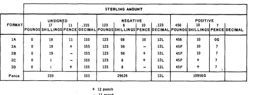
Table 3-3 shows examples of sterling amounts written in Format 1A.
STERLING AMOUNT
UNSIGNED NEGATIVE POSITIVE
FORMAT POUNDS
lA 0
2A 0
26 0
2C 0
20 0
Pence
17 11 SHilLINGS PENCE
19 11
19 +
19
-I
-I +
239
.155 123 DECIMAL POUNDS
155 155 155 155 155 155 123 123 123 123 123
+
12 punch - 11 punch8 10 .123 456 10 SHilLINGS PENCE DECIMAL POUNDS SHilliNGS
08 10 12l 456 10
08
-
12l 45F 1008 + 12l 45F 10
8 + 12l 45F +
8
-
12l 45F +29626 12l 10956G
Table 3-3. Sterling Amounts Expressed in Available Formats of Notation
7 PENCE OG 7 7 7
7 ,
DECIMAL
3
Up .. ·H20
Rev. 2UNIVAC 9200/920011/9300/9300 II
CARD UTILITY PROGRAMS
3.1.2. Format 1B
3
SECTION:
Format 1B is the same as format 1A except that the information is packed rather than unpacked.
3.1.3. Format 2
Format 2 is used for both input and output. Input cards are read and output cards punched in this format.
PAGE:
Format 2 permits a maximum of 10 positions for pounds and 3 positions for decimals. Shillings and pence may be represented in either the British Standards Institution (BSI) or the Hollerith code.
3.1.3.1. Shillings
• BSI Code
A single column is used to represent the shillings field. Amounts of 0 through 9 are indicated by the punches 0 through 9. Ten shillings are represented by a 12 punch in the column. Eleven through 19 shillings are represented by the A through I punches, respectively.
• Hollerith Code
Two columns are used to represent the shillings field. Decimal notation is used, the first column representing the tens position (that is, it contains either 0 or 1) and the second representing the units (digits 0 through 9).
3.1.3.2. Pence
• BSI Code
The pence field is represented by a single column. Amounts of 0 through 9 are indicated by the punches 0 through 9. Ten pence are represented by a 12 punch;
11 pence by an 11 punch.
• Hollerith Code
The Hollerith code is similar to the BSI code in that both use a single column to represent pence. Amounts of 0 through 9 are indicated by the punches 0 through 9. However, 10 pence are represented by an 11 punch; 11 pence by a 12 punch.
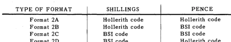
3.1.3.3. Format 2 Types
Format 2 may be used in any of the following combinations of BSI and Hol!erith code.
TYPE OF FORMAT SHILLINGS PENCE
Format 2A Hollerith code Hollerith code
Format 2B Hollerith code BSI code
Format 2C BSI code BSI code
Format 2D BSI code Hollerith code
Table 3-2 illustrates the maximum sizes of format 2. Refer to Table 3-3 for examples of sterling amounts written in format 2.
lJP-4120 Rev. 2
3.1.3.4. Signs
UNIVAC 9200/9200 11/9300/9300 II CARD UTILITY PROGRAMS
3 SECTION:
The sign is fo.und in the least significant digit o.f the decimal po.rtio.n o.f a sterling field. Ho.wever, if no. decimal fractio.ns o.f a penny exist in the field, the zo.ne punch identifying the sign is placed in the units po.sitio.n o.f the po.unds field.
The sign co.des are as fo.llo.ws: - (minus) = 11 punch
+
(plus) = 12 punch o.r blankNOTE: An 11 punch always requires a digit underpunched in the same co.lumn. A 12 punch in the appro.priate po.sitio.n is always used to. signify po.sitive o.utput amo.unts.
3.1.3.5. Leading Zero.s
Leading zero.s can be represented by blanks in sterling input fields. 3.1.4. Pence Fo.rmat
The pence fo.rmat is a "pence o.nly" no.tatio.n o.f a sterling amo.unt; all po.und and shilling fields are co.nverted to' pence.
Pence fo.rmat allo.ws fo.r a maximum o.f 16 po.sitio.ns: 13 po.sitio.ns fo.r pence and 3 decimal po.sitio.ns.
Table 3-2 illustrates the maximum size o.f the pence fo.rmat. Refer to' Table 3-3 fo.r an example o.f sterling amo.unts in pence fo.rmat.
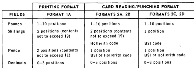
The pence no.tatio.n is o.perated o.n with decimal arithmetic instructio.ns. A summary o.f sterling no.tation fo.rmats is given in Table 3-4.
PRINTING FORMAT CARD READING/PUNCHING FORMAT
FIELDS FORMAT lA FORMATS 2A, 28 FORMATS 2C, 2D
Pounds 1-10 positions 1-10 positions 1-10 positions
Shillings 2 posi tions (contents 2 positions (contents 1 position not to exceed 19) not to exceed 19)
Hollerith code BSI code , Pence 2 pos itions (contents 1 position 1 position
not to exceed 11) BSI or Hollerith code BSI or Holleri th code
Decimals 0-3 positions 0-3 positions 0-3 positions
Table 3-4. Summary of Sterling Notation Formats
5
UP-4120
Rev. 2UNIVAC 9200/9200 11/9300/9300 II
CARD UTILITY PROGRAMS
SECTION.3
PAGE:
3.2. CONVERSION ROUTINES
3.3.
There are 11 routines to convert one format to another. Table 3-5 lists the conversion routines and shows the relationship of the routines to the individual formats.
CON· CONVERSION APPROX. APPROX. MAXI· FORMAT
VERSION NUMBER MUM TIME FOR
ROUTINES FROM TO OF BYTES EXECUTION* INPUT OUTPUT
RIA 2A 16 94 1.2 16 bytes 9 bytes
unpacked packed
R16 26 16 94 1.2 16 bytes 9 bytes
unpacked packed
RIC 2C 16 116 1.4 15 bytes 9 bytes
unpacked packed
RID 20 16 116 1.4 15 bytes 9 bytes
unpacked packed
R3 16 Pence 126 5.0 9 bytes 9 bytes
packed packed
R4 Pence 16 118 5.8 9 bytes 9 bytes
packed packed
R5A 16 2A 78 1.0 9 bytes 16 bytes
packed unpacked
R56 16 26 78 1.0 9 bytes 16 bytes
packed unpacked
R5C 16 2C 110 1.3 9 bytes 15 bytes
packed unpacked
R50 16 20 110 1.3 9 bytes 15 bytes
packed unpacked
R6** 16 lA 56 1.0 9 bytes 17 bytes
packed unpacked
*In milliseconds
**Conversion routine R6 also suppresses leading zeros in the tens digit of the shillings and pence fields.
Table 3-5. Conversion Routines
USING CONVERSION ROUTINES
Anyone of the routines may be used individually or in conjunction with others to meet any user's requirement.
3.3.1. Common Work Area
The problem program delivers data to be processed by a sterling conversion routine by storing the data in a common work area. The sterling conversion routine also uses the common work area to deliver the converted data to the problem program. This common work area must be supplied by the problem program, must be 24 bytes long, and must be labeled SWKA.
UP-4120 Rev. 2
UNIVAC 9200/9200 11/9300/9300 II
CARD UTILITY PROGRAMS SECTION:
3
3.3.2. Converting Data
1
,
, 1
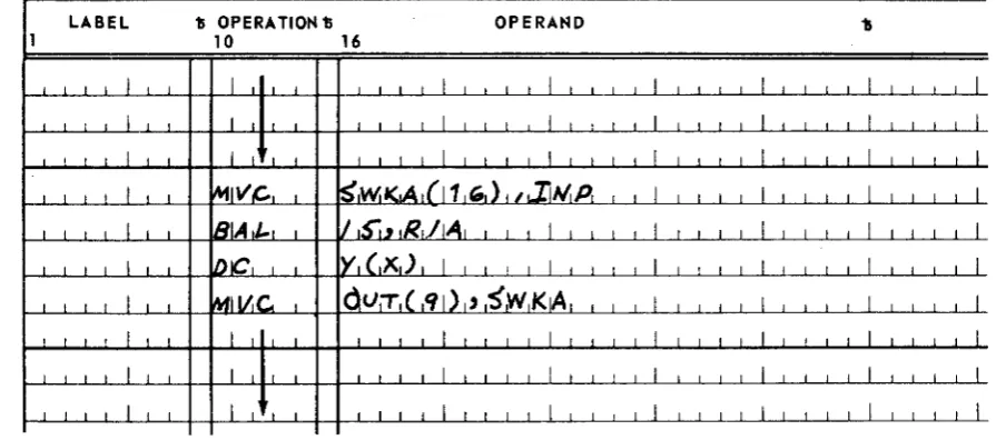
When the problem program requires conversion of data, it places the data in SWKA and then enters the sterling conversion routine by means of a BAL instruction that uses register 15 and that branches to the name of the routine. The BAL instruction should be immediately followed by a half-word constant containing, right justified in binary notation, the number of fractional pence decimal places in the data to be converted. The number may be 0 through 3. When the sterling conversion routine has finished the conversion, it stores the converted data in SWKA and returns control to the instruction immediately following the constant specifying the number of decimal places.
Register 14 is used by the routines as a working register. The sterling routines do not save the contents of register 14. Therefore, the problem program should not have usable information in register 14 when linking to the sterling routines. Figure 3-1 illustrates a typical use of the routine R1A, converting format 2A to format lB. The letter x in the DC directive must be replaced by one of the digits 0, 1, 2, or 3 to indicate the number of decimal positions required.
LABEL 11 OPERA 1101'111 OPERAND 'b
10 16
I I I 1 1 1
I
1 I 1 1I
1 I I II
1 I I 1I
1 1 I 1I
1 1 I 1i I i i i 1 1
J
I I I I I
I
i,
, I
1 ~IVC.,S',Wi
'<A
l
j1
WI) , I.,Ii",
P,I
,
,
I
1 1 1 1I
I i i
iSIA,t-,
1I
JS"J.~lRL/jAll
L 1 j J 1 j I I I II
II
I
I
~1 j
i I
1 1IDIC\
Y,(,X)
I,
I,
I I,
I
I I 1 1I
I I I 1I
1 I 1 II
I
MII!JC.
OV:T
1( '11)1'SWK~
II
JJ
,
, I I I I I I I i1
i I I
,
I i iI
j 1 i
I
I 1 I ,I
1
j 1 II
Figure 3-7. Linking Sequence, Format 204 to Format 7 B
3.4. INCLUSION OF ROUTINES INTO THE PROBLEM PROGRAM
The user may incorporate sterling conversion routines into his problem program in either of two ways. He may include the sterling routines in his source program for joint assembly, or he may assemble the sterling routines separately and link them to the problem program.
The sterling conversion routine R3 requires multiplication. The sterling conversion routine R4 requires division. These two routines are written on the assumption that they are to be used with a configuration that does not include the multiply and divide instructions. Therefore, the following is required:
PAGE:
a. If the assumption is true, then whenever routine R3 or R4 is included in a program, the multiply/divide subroutine named MPDP must also be included.
UP-4120
Rev. 2
UNIVAC 9200/9200 11/9300/9300 II
CARD UTILITY PROGRAM 3
SECTION.
b. If the assump tion is false, then the BAL instructions with the following format should be removed from routines R3 and R4 before they are assembled. There are two such instructions in each of these routines.
LABEL "IS OPERATION 15 OPERAND
unused BAL 15,MPDP
3.4.1. Joint Assembly
If the user desires to assemble the sterling routine(s) together with his source program, he incorporates the work area definition (SWKA) and the sterling routines in the source program. The sterling routine object program becomes an integral part of the obj ect program.
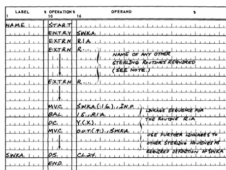
3.4.2. Separate Assembly
For separate assembly of the sterling routine package, which is composed of the desired sterling routines and an END statement, the user must include the follow-ing in the problem program:
• The name of the common work area (SWKA) must be identified by means of an ENTRY statement.
• The names of all the sterling routines used must be identified by means of EXTRN statements.
• SWKA must be defined.
Figure 3-2 illustrates the coding for the main program for separate assembly of sterling routines.
The letter x in the operand field of the DC statement in the calling sequence shown in Figure 3-2 must be replaced by one of the digits 0, 1, 2, or 3 to indicate the number of decimal positions required.
8
UP-4120
Rev. 2
LABEL
UNIVAC 9200/9200 11/9300/9300 II
CARD UTILITY PROGRAMS
11 OPERATION 1; OPERAND
10 16
3 SECTION:
NOTE: Those sterling routines denoted by EXTRN statements must also be assembled separately and then linked with the problem program.
Figure 3-2. Coding the Problem Program for Separate Assembly
of the Sterling Routines
9
UP-4120 Rev. 2
UNIVAC 9200/9200 11/9300/9300 II
CARD UTILITY PROGRAMS
4. MEMORY
4.1. GENERAL
4
SECTION:
DUMP ROUTINE
The memory dump routine is a means of printing the entire contents of main storage or a specified portion of it. The routine is provided in compressed code format and, by use of appropriately prepared macro instructions in the preassembly macro pass, can be generated in the form of a closed subroutine or in the form of a self-loading card deck.
In the closed subroutine form, the source code generated by the preassembly macro pass may be incorporated into the problem program at assembly time or may be assembled separately from the program and incorporated into the program at linker time. The routine may then be executed by a BAL instruction in the problem program.
In the self-loading form, the source code generated by the preassembly macro pass should be assembled as an independent program. The object code of the self-loading memory dump routine can then be loaded from the online card reader or the 1001 card controller when a program ends or aborts. The routine, if loaded into an area which will not be cleared or overlayed by a su bsequent program, can remain resident and can be accessed manually from the control console as often as required.
The beginning and ending locations of the main storage area to be dumped are defined by two type Y define-constant (DC) statements labeled MBGN and MEND. The follow-ing is an example of the format of these two statements.
LABEL
MBGN MEND
where:
15 OPERATION D DC DC
OPERAND
Y(c) Y(c)
c, the constant subfield, represents either an absolute or a relocatable main storage address
The dump locations specified in these DC statements may be changed by replacing the appropriate cards contained in the source code deck generated by the pre-assembly macro pass. This method applies to the closed subroutine and the self-loading forms of the memory dump routine. If the source deck has been assembled, then the beginning and ending dump locations are changed by submitting appropriately prepared replace (REP) cards to the squeeze routine. (Refer to Section 6 for a
detailed discussion of the purpose and function of the squeeze routine.) The REP cards can also be used at linker time if the subroutine form of the memory d\lmp is being incorporated into the problem program by the linker routine.
Finally, in the case of the subroutine form, the problem program can externally reference the memory dump routine in order to change the beginning and ending dump locations at execution time.
In addition to the data contained between the beginning and ending memory dump locations specified by the routine, the memory dump routine always prints the contents of the fixed hardware output area and the control area (address 0 through
127).
1
UP-4120 Rev. 2
UNIVAC 9200/9200 11/9300/9300 II
CARD UTILITY PROGRAMS
4.2. CONTENTS OF CONTROL AREA
4
SECTION:
The portions of the control area used by the memory dump routine during its execu-tion are the input/output program-state-control (I/O PSC) word, I/O registers 13
through 15, and the line advance control byte (location 80). These areas are altered by the memory dump routine. However, the subroutine form of the memory dump routine preserves the initial content s of these areas before beginning its dump execution proper. These preserved contents can be found at the following locations:
• MD+8 through MD+ 11 for the I/O PSC
• MD+12 through MD+17 for I/O registers 13 through 15 • MD+18 for the line advance control byte
• MD+24 for the processor PSC
The beginning and ending locations of the dump can be found at the following locations:
• MD+2 through MD+3 for the MBGN constant • MD+4 through MD+5 for the MEND constant
MD is the first location of the routine loaded into main storage. In the self-loading form of the routine, the contents of the part of control area stored in addresses 0 through 79 are destroyed by the loader when the routine is loaded.
4.3. PRINT FORMAT
The print format of the memory dump is as follows: • Lines are double-spaced.
• Contents of the fixed-hardware-printer output area are dumped first and printed on print line 1 without format modification.
• Contents of the control area (locations 0 through 127) are dumped next and are printed on print lines 2 through 5 in the format described in this paragraph. • Contents of the memory dump proper are dumped last. This portion of the dump
begins on print line 6 in the format described in this paragraph.
• The print format for the memory dump, with the exception of print line 1, which contains the fixed-hardware-printer output area, is as follows:
The address of the first byte printed on each line is presented in hexade,cimal notation, positioned at the left margin of the line, and separated from the rest of the line by two spaces.
The contents of each byte are represented in two consecutive print positions. The left position represents the zone of the byte and the right position repre-sents the digit of the byte. Both positions are expressed in hexadecimal notation.
Bytes are formed into eight-byte groups (16 printed characters). Groups are separated by two spaces. However, bytes within each group are not separated.
2
UP-4120 Rev. 2
UNfVAC 9200/9200 11/9300/9300 II
CARD UTILITY PROGRAMS
SECTION'4
Four eight-byte groups are printed on each of the four print lines (2 through 5) containing the contents of the control area.
PAGE.
The number of eight-byte groups printed for each line of the memory dump proper depends upon the printer used. That is, for a printer with 96 print positions, five eight-byte groups are printed per line; a printer with 120 print positions prints six eight-byte groups per line; and a printer with 132 print positiol1s prints seven eight-byte groups per line.
Under certain conditions, an entire print line of asterisks may appear in the printing of the memory dump proper. The printing of these asterisks indicates that each half-word contained in the line is equal to the last half-word of the previous line. After a line of asterisks has been printed, no more output is produced until a line in which a half-word not equal to the last half-word of the previous line is detected. With this line, the routine returns to producing lines of print in the norma 1 output format. The last line of the memory dump proper is always printed.
• The paper is automatically skipped to the horne paper position after the memory dump has been completed.
4.4. MAIN STORAGE REQUIREMENTS
The main storage requirements of the memory dump routine are based upon the form of the routine. If the routine is in the self-loading form, the storage requirement is fixed at 590 bytes. If the routine is in the closed subroutine form, the storage re-quirem ents are determined by the number of print positions specified in the print position keyword parameter of the dump-subroutine (MOSBR) and the memory-dump-self-loading-form (MOSLF) macro instructions. The number of bytes and their associated POS parameter values are as follows:
622 bytes when MOSBR POS=96 646 bytes when MOSBR POS=120 658 bytes when MOSBR POS= 132
UP-4120
Rev. 2UNIVAC 9200/920011/9300/9300 II
CARD UTILITY PROGRAMS SECTION:
4
4.5.'
CHARACTERISTICS OF CLOSED SUBROUTINE FORM OF MEMORY DUMP ROUTINEA description of the macro instructions used for the closed subroutine form of the memory dump, as well as a sample of the problem program coding used to produce a memory dump, is provided in the paragraphs that follow.
4.5.1. Memory-Dump-Subroutine (MDSBR) Declarative Macro Instruction
The" MDSBR declarative macro instruction consists of four keyword parameters which define the number of print positions per line, the character set of the print bar, and the beginning and ending locations of the dump. The format of the MDSBR macro instruction is as follows:
LABEL 15 OPERATION 15 OPERAND
unused MDSBR POS =
{
i~o}
,
• Print Position (POS) Keyword Parameter
CH =
132
'48
t
t
63f
[ ,BGN=nnnnn] [ ,END=nnnnn]
The POS keyword parameter defines the maximum number of valid print positions 'to appear in a line of print for a specific routine generated. If the maximum
number of print positions of the printer being used exceeds that specified by the POS parameter, the remaining print positions of the line should be dis-regarded. The formats of the POS parameter are as follows:
POS=96
This format of the keyword parameter limits the number of print positions per line to 96.
POS=120
This format of the keyword parameter limits the number of print positions per line to 120.
POS=132
This format of the keyword parameter limits the number of prin t positions per line to 132.
• Character Set (CH) Keyword Parameter
The CH keyword parameter is used to specify the character set of the print bar to be used. Since two character sets are available, the CH keyword parameter can be specified in the one to be used. The CH keyword has the following formats:
UP-4120 Rev. 2
UNIVAC 9200/9200 11/9300/9300 II CARD UTILITY PROGRAMS
CH=48
4
SECTION:
This format of the CH keyword parameter specifies a print bar with 48 valid characters.
CH=63
This format of the keyword parameter specifies a print bar with 63 valid characters.
• Dump Beginning Address (BGN) Keyword Parameter
The BGN keyword parameter specifies the main storage location at which the dump is to begin. The use of the BGN is optional. If the BGN parameter is omitted, a main storage location of 256 is assumed by the routine, and the memory dump will start at that location. The format of the BGN parameter is as follows:
BGN=nnnnn
The value for nnnnn can be any number from 256 th.rough 32767. It should be noted that the memory dump routine erases the four least significant bits of the beginning address when it starts to produce the memory dump. Therefore, the address which is nearest to but less than the specified address and which is an integral multiple of 16 is adopted by the routine as the actual beginning address for the memory dump .
• Dump Ending Address (END) Keyword Parameter
The location at which the memory dump is to end is specified by the END key-word parameter. The use of the END parameter is also optional. However, the value of 8191 is adopted by the routine as the ending address if the END parameter is omitted. The format of the END keyword parameter is as follows:
END=nnnnn
The value for nnnnn can be any number from 256 through 32767. The actual ending location of the memory dump may exceed that specified by the END parameter. This is due to the fact that the routine always produces the memory dump in groups of eight bytes incl uding the entire eight bytes in wh ich the specified ending location is contained. (Refer to 4.3 for information concern-ing print format for the memory dump.) If the calculation of the address of the last eight bytes to be dumped produces an address that is beyond the memory limits of the machine, the memory dump terminates in a processor abnoqnal condition.
5
UP-4120 Rev. 2
UNIVAC 9200/920011/9300/9300 II
CARD UTILITY PROGRAM
4.5.2. END Imperative Macro Instruction
4
SECTION:
The END imperative macro instruction must follow the MDSBR macro instruction, which is described in 4.5.1. The function of the END macro is to define the com-pletion or end of the closed subroutine having the name specified by the symbol contained in the operand of this instruction. The format for the END macro in-struction used with the closed-subroutine form of the memory dump is as follows:
LABEL D OPERATION D OPERAND
unused END MENT
4.5.3. Instructions Required for Execution of Closed Subroutine
The closed subroutine for memory dump is executed when the properly coded BAL instruction is encountered in the problem program. The entry point to the closed subroutine is defined by the MENT symbol contained in the operand field of the BAL instruction. Also contained in the operand field of the BAL instruction is the parameter that specifies processor register 15 as the return register. The branch from the problem program to the closed subroutine can be made by use of the following coding:
LABEL D OPERATION '\) OPERAND
unused BAL 15,MENT
The memory dump routine is designed to be entered in processor mode, and it returns to processor mode before returning control to the problem program. The memory dump itself is executed in I/O mode. Three symbols, MBGN, MEND, and MENT, are declared by ENTRY directives in the closed-subroutine form of the memory dump routine. Thus, the memory dump routine and problem program can each be assembled separately and still be linked togethe]:' by EXTRN directives, . which are declared in the problem program.
When the memory dump is in the form of a closed subroutine, it may be necessary to change the beginning and ending locations of the dump in the problem program at running time. Accordingly, the memory dump routine has the following symbols for the constant areas that specify beginning and ending locations:
• MBGN for BGN address constant area. The length is a half-word. • MEND for END address constant area. The length is a half-word.
A sample of the problem program coding which produces a memory dump from loca-tions 1000 through 2000 is as follows:
6
UP-H20
Rev. 2
'"---,,,
LABEL
UNIVAC 9200/9200 11/9300/9300 II CARD UTILITY PROGRAMS
11 OPERA TlON 1)
10 16
SECTION:
OPERAND
Since MBGN and MEND are placed in adj acent main storage locations, the preceding coding can also be written as follows:
4
7
UP-412()' Rev. 2
UN I VA C 9200/9200 11/9300/9300 II
CARD UTILITY PROGRAMS
4.6. CHARACTERISTICS OF SELF-LOADING FORM OF MEMORY DUMP ROUTINE
4
SECTION,
The following paragraphs contain descriptions of the macro instructions, programming considerations, and operating instructions for the self-loading form of the memory dump routine.
4.6.1. Memory-Dump-Self-Loading-Form (MDSLF) Declarative Macro Instruction
The MDSLF declarative macro instruction contains eight keyword parameters. These parameters define the line length and character set of the memory dump printout, as well as the location at which the routine is to be loaded, and which card reader unit is to be used. The beginning and ending locations of the memory dump are also provided as keyword parameters of this macro instruction. The format of the MDSLF macro instruction is as follows:
LABEL
15 OPE RA TION 15
[name] MDSLF POS
=
~i~o
t ,
/132 \
OPERAND
[~
'
BG N =nnnnn,END=nnnnn~J
,BGN=nnnnn ,LOAD=nnnnn
,END=nnnnn
• Print Position (POS) Keyword Parameter
The POS keyword parameter defines the maximum number of valid print positions to appear in a line of print for a specific routine generated. If the maximum number of print positions of the printer being used exceeds that specified by the PQS parameter, then the remaining print positions of the line are filled with hash and are to be disregarded. The formats of the POS parameter are as follows:
POS=96
This format of the keyword paramter limi ts the number of print positions per line to 96.
UP-4120
Rev. 2
UNIVAC 9200/9200 11/9300/9300 II
CARD UTILITY PROGRAMS
POS=120
4
SECTION:
This format of the keyword parameter limits the number of print positions per line to 120.
POS=132
This format of the keyword parameter limits the number of print positions per line to 132.
• Character Set (CH) Keyword Parameter
The CH keyword parameter is used to specify the character set of the print bar to be used. Since two character sets are available, the CH keyword parameter is used to specify the one to be used. The formats for the CH keyword parameter are as follows:
CH=48
This format specifies a print bar with 48 valid characters.
CH=63
This format specifies a print bar with 63 valid characters.
• Dump Beginning Address (BGN) Keyword Parameter
The BGN keyword parameter is an optional parameter used to specify the main storage location at which the memory dump is to begin. The value specified in this parameter may be any number from 256 through 32767. It should be noted, however, that this parameter must be omitted if the MEM parameter is used in this instruction. If both the BGN parameter and the MEM parameter are omitted from the instruction, the memory address 256 is adopted as the beginning address of the memory dump. The format for the BGN keyword parameter is as follows:
BGN=nnnnn
The value of nnnnn can be any number from 256 through 32767. The actual beginning location, however, must be an address which is an integral multiple of 16. Therefore, if the address specified by the BGN parameter is not an integral multiple of 16, the dump starts at the next lower address that is a multiple of 16.
• Dump Ending Address (END) Keyword Parameter
The END parameter is also an optional parameter. It is used to specify the main storage location at which the memory dump is to end. The value specified in this parameter may be any number from 256 through 32767. The END parameter must be omitted if the MEM parameter is used in the instruction. If both the END parameter and the MEM parameter are omitted from the instruction, a memory address of 8191 is adopted as the ending address of the memory dump. The format for the END keyword parameter is as follows:
END=nnnnn
9
UP-4120
Rev. 2
UNIVAC 9200/9200 11/9300/9300 II
CARD UTILITY PROGRAM
SECTION: 4The value of nnnnn can be any number from 256 through 32767. The actual ending location of the dump must be an address which is an integral multiple of 8. Therefore, if the address specified by the END parameter is not an i!ltegral multiple of 8, the dump ends at the next higher address that is a multiple of 8.
• LOAD Keyword Parameter
The LOAD keyword parameter specifies the beginning main storage location into which the memory dump routine is to be loaded. The value specified in this parameter may be any number from 260 through 32100. The LOAD parameter must be omitted if the MEM parameter is used in this instruction. The format of the LOAD instruction is as follows:
LOAD=nnnnn
The value of nnnnn can be any number from 260 through 32100 .
• Memory (MEM) Keyword Parameter
The MEM keyword parameter is used to specify the main storage size for a routine that is to dump the entire contents of main storage. It also indicates that the memory dump routine is to be loaded into the highest locations of main storage. If the BGN·, END, or LOAD parameters are used in the macro instruc-tion, then the MEM parameter must be omitted. The formats of the MEM parameter used for the various sizes of main storage are as follows:
MEM=8K
This format of the MEM parameter is used when the entire contents of an 8K main storage are. to be dumped.
MEM=12K
This format of the MEM parameter is used when the entire contents of a 12K main storage are to be dumped.
MEM=16K
This format of the MEM parameter is used when the entire contents of a 16K main storage are to be dumped.
MEM=24K
This format of the MEM parameter is used when the entire contents of a 24K main storage are to be dumped.
MEM=32K
This format of the MEM parameter is used when the entire contents of a 32K main storage are to be dumped.
10
PAGE:
-UP-4120 Rev. 2
UNIVAC 9200/9200 11/9300/9300 "
CARD UTILITY PROGRAMS
• Reader (RDR) Keyword Parameter
4
SECTION:
The RDR keyword parameter is an optional parameter that is used only when the UNIVAC 1001 Card Controller is used as the routine load device as opposed to the online card reader. If the routine is to be loaded from the online card reader, then the RDR parameter and its associated CHAN parameter must be omitted from the instruction. The format for the RDR parameter is as follows:
RDR=1001
• Channel (CHAN) Keyword Parameter
PAGE:
The CHAN keyword parameter is an optional parameter which is used to specify the number of the channel to which the card controller is attached. This para-meter, therefore, is only used when the RDR parameter is included in the instruc-tion format. If the RDR is omitted, then the CHAN keyword parameter must also be omitted. The formats for the CHAN keyword parameter are as follows:
CHAN=7
This format, specifies that the 1001 card controller is connected to channel number 7.
CHAN=8
This format specifies that the 1001 card controller is connected to channel number 8.
CHAN=9
This format specifies that the 1001 .card controller is connected to channel number 9.
CHAN=10
This format specifies that the 1001 card controller is connected to channel number 10.
A program name may be defined for the memory dump by entering a valid name in the label field of the MDSLF macro instruction. The use of the label field is optional. However, if its use is desired, it may contain any valid symbol desired, except that the characters Y or
Q
may not be used as the second character in the symbol. If the symbol is omitted, a label defined as MD is assigned as the program name by the macro library when the routine is generated.UP-4120
Rev. 2UNIVAC 9200/9200 11/9300/9300 II
CARD UTILITY PROGRAMS
4.6.2. END Imperative Macro Instruction
4
SECTION:
The END imperative mac;ro instruction must follow the MDSLF instruction in the card deck. The format of the EN];) macro instruction for the self-l~ading memory dump routine is the same.as that which follows the MDSBR instruction used for the closed-subroutine form. The END macrQ instruction identifies the end of the routine and specifies the name of the routine. The format of the END macro instruction is as follows:
LABEL D OPERA TION D OPERAND
un~sed END MENT
4.6.3. Programming Considerations
After the source code has been generated by the preassembly macro pass, it is assembled to produce a self-~oading object deck. Before loading the object deck, the A and
J
cards (first and second cards of the object deck) must be removed so that the first card to be loaded contains a Q in column 2 ..If a problem program is expected to abort or to require a memory dump subsequent to running, it is preferable to load the memory dump routine prior to the execution of the problem program,. The routine is therefore resident in memory during the exe-cution of the problem prog~am and can be accessed by manual operation at the con-trol console after the problem program aborts. When using this method, make certain that the problem program does not overlay the memory routine or clear the storage area in which the routine resides. As a precautionary measure the following steps should be taken:
a. Assemble a dump routine which is loaded into the high order areas of main storage.
b. Set the limits of the problem 'program so that the highest location used corre-sponds to the following:
Location ~Hexadecimal) Main Storage Size
lDB2 8K
2DB2 12K
3DB2 16K
SDB2 24K
7DB2 32K
c. When linking the problem program to a loader, set the L?HI-Iabeled EQU directive to the appropriate hexadecimal limit specified in step b. This defines the last location of main storage to be cleared.
12
UP-4120 Rev. 2
UNIVAC 9200/9200 11/9300/9300 II
CARD UTILITY PROGRAMS
SECTION: 4d. When linking the problem program to a loader, set the L? AR-Iabeled EQU directive to the appropriate hexadecimal limit specified in step b minus 340 if the online reader is used as the loading device or to minus 444 if the card controller is used as the loading device. The resulting value for L? AR specifies the beginning of the read area for the load routine.
NOTE: If the problem program is written in RPG, the requirements specified in steps b, c, and d are satisfied by placing the character D in column 80 of the RPG header control card.
4.6.4. Operating Instructions
A programmer may determine the status of the processor by performing the operations specified in the following paragraphs. This must be accomplished prior to the performance of the memory dump since the status conditions stored are destroyed once the memory dump is initiated. The operations required to obtain the status of the processor are initiated from the operator's panel of the control console.
NOT E: Make certain that the CLEAR switch is not set prior to performing this
procedure.
a. Check for error conditions as follows:
(1) Set PROC I/O switch to position PROC.
(2) Press and release switch A; observe DISPLAY SELECT indicators. If
the third DISPLAY SELECT indicator from the left is on, an address error exists. If the fourth indicator from the left is on, a memory parity error exists.
b. Determine processor state as follows:
(1) Set PROC I/O switch to position PROC.
(2) Press and release switch B; observe DISPLAY SELECT indicators. If
the third indicator from the left is on, the central processor unit is in the I/O state and the I/O state location counter points to the next instruc-tion to be executed. (The processor state control points to one instrucinstruc-tion beyond the point at which the processor left the processor state.) If the third indicator from the left is off, the processor is in the processor state and the processor state location counter points to the next instruction to be executed. The I/O state location counter is normally reinitialized by the supervisor when an exit from the I/O state takes place.
c. Press and release the CLEAR switch.
d. If the memory dump routine is not resident, display the contents of the follow-ing locations which are destroyed by the operation of the memory dump loader.
UP-4120 Rev. 2
UNIVAC 9200/9200 11/9300/9300 II
CARD UTILITY PROGRAM
Location (Hexadecimal) 2-3
12-13 20-2F 30-3F 42-43
<