Volume 2006, Article ID 82023, Pages1–12 DOI 10.1155/ASP/2006/82023
Joint Source-Channel Coding by Means of
an Oversampled Filter Bank Code
Slavica Marinkovic and Christine Guillemot
IRISA-INRIA, Campus de Beaulieu, 35042 Rennes Cedex, France
Received 1 September 2004; Revised 5 April 2005; Accepted 7 April 2005
Quantized frame expansions based on block transforms and oversampled filter banks (OFBs) have been considered recently as joint source-channel codes (JSCCs) for erasure and error-resilient signal transmission over noisy channels. In this paper, we consider a coding chain involving an OFB-based signal decomposition followed by scalar quantization and a variable-length code (VLC) or a fixed-length code (FLC). This paper first examines the problem of channel error localization and correction in quantized OFB signal expansions. The error localization problem is treated as anM-ary hypothesis testing problem. The likelihood values are derived from the joint pdf of the syndrome vectors under various hypotheses of impulse noise positions, and in a number of consecutive windows of the received samples. The error amplitudes are then estimated by solving the syndrome equations in the least-square sense. The message signal is reconstructed from the corrected received signal by a pseudoinverse receiver. We then improve the error localization procedure by introducing a per-symbol reliability information in the hypothesis testing procedure of the OFB syndrome decoder. The per-symbol reliability information is produced by the soft-input soft-output (SISO) VLC/FLC decoders. This leads to the design of an iterative algorithm for joint decoding of an FLC and an OFB code. The performance of the algorithms developed is evaluated in a wavelet-based image coding system.
Copyright © 2006 Hindawi Publishing Corporation. All rights reserved.
1. INTRODUCTION
Various joint source-channel coding approaches, guided by an optimum tradeoffbetween compression efficiency and er-ror and/or erasure resilience depending on the link charac-teristics, have been considered in order to improve multime-dia signal transmission over noisy channels. Here, we focus on JSCC techniques based on quantized redundant signal expansions by means of OFB. As the signal representation in this approach is redundant, an OFB-encoded stream has error-resilient features. Error-control coding and signal de-composition are thus integrated in a single block. The error-correcting code thus allows also to suppress some quantiza-tion noise effects.
So far, the research in this area has been concentrated mainly on the study of oversampled transform codes (OTC) which are OFB codes with polyphase filter orders equal to zero. The OTC can be viewed as real-number block codes, while the OFB codes can be associated to real-number con-volutional codes. Decoding of real-number block codes has been considered by many authors [1–7]. Oversampled block transforms like DFT codes have been shown to be BCH codes over the real field [8,9]. DFT or DCT codes have also been considered as joint source-channel block codes to obtain
robustness to erasures [4–6,10] and impulse noise errors [2,3,11–13]. Filter bank frame expansions have also been studied to achieve resilience to erasures [14–16]. In [14], the authors have shown correspondences between OFB and frames inl2(Z). They have shown that if the frames satisfy some properties, the mean-square reconstruction error can be minimized. The authors in [17] have studied oversam-pled tree-structured filter banks for erasure recovery. How-ever, there has not been many studies of OFB codes for im-pulse error correction.
used than that of standard syndrome decoding. The localiza-tion procedure usually relies on the hypothesis testing the-ory. For example, in both [18, 19], the error localization is motivated by theM-ary hypothesis testing theory. How-ever, they differ in the way the likelihood values for hy-pothesis testing are calculated. In [18], the activity detec-tion (presence of impulse errors) is based on forming the quadratic terms for each log-likelihood ratio calculated from the syndrome covariance matrices under various hypotheses. In [19], the error localization is based on the pdf of syndrome norm.
The error localization procedure presented here is in-spired from [18]. However, in contrast to [18] where the de-tection of the increased noise statistics due to impulse errors employs quadratic forms of likelihood ratios [1,18], we ap-ply a minimum total probability of error test [20]. That is, we compute the a posteriori probability of each hypothe-sis, and choose the largest. We consider two channel impulse noise models. We first consider a Bernoulli-Gaussian impulse noise model as in [18,19]. We then introduce a quantizer-dependent impulse noise model. This model takes into ac-count the discrete nature of the impulse errors at the out-put of the VLC/FCL decoders. For these two impulse noise models, the error localization procedure based onM-ary hy-pothesis testing theory is presented. Each possible error posi-tion within a window of the received samples is considered as a separate hypothesis. The localization procedure selects the hypothesis with a maximum a posteriori probability. The er-ror amplitudes are then estimated by solving the syndrome equations in the least-square sense. The message is recon-structed from the corrected received sequence by a pseudoin-verse receiver. We further consider using the soft informa-tion, that is, per-symbol reliability informainforma-tion, produced by the SISO VLC/FLC decoder in the localization procedure of the OFB decoder. The a posteriori probabilities of the source symbols produced by the SISO VLC/FCL decoders are used in the calculation of the hypothesis a priori probabilities. The results show that introducing the soft information in the er-ror localization procedure in this way improves the proba-bility of detection and decreases the MSE. An iterative algo-rithm for joint decoding of the FLC and an OFB code is pre-sented. In this algorithm, the trellis for the decoding of the FLC-encoded source coefficients modeled by the first-order Markov source is iteratively pruned with the help of the hy-pothesis a posteriori probabilities. This is done based on the information on the symbols for which errors have been de-tected in the OFB syndrome decoder. The performance of these algorithms has been tested in the image compression system based on the subband decomposition by a wavelet fil-ter bank.
The paper is organized as follows.Section 2introduces the general framework and problem statement. OFB codes are described in Section 3. Section 4 describes the SISO VLC/FLC decoders. The impulse error models and the OFB syndrome decoding algorithms are described inSection 5. It-erative algorithm for decoding of the FLC and OFB chain is presented in Section 6. Simulation results are given in
Section 7.
2. GENERAL FRAMEWORK AND PROBLEM STATEMENT
The block diagram of the considered encoding/decoding chain is shown inFigure 1. The encoding chain consists of an OFB followed by a scalar quantization and a fixed or variable-length coder. An OFB provides an oversampled frame expan-sion of the input signal. A set of vectorsΦ = {φi}i∈Iin a
Hilbert spaceHis a frame if for anyx=0,
Ax2≤
i∈I
x,φi2
≤Bx2, (1)
wherex,ydenotes the inner product ofxandy,Iis the in-dex set, andA > 0, andB < ∞are constants called frame bounds [14]. The coefficients of the expansion are
quan-tized and encoded. In the sequel, both fixed- and variable-length codes are considered. When considering a system with a variable-length code (VLC), we employ a scalar quantizer with a dead zone and with a number of levelsNk
Q for each
subbandk,k =0,. . .,N−1. In the system with an FLC, we employ a Lloyd-Max scalar quantizer with the same number of quantization levelsNQk. The encoded subbands are
trans-mitted over an additive white Gaussian noise (AWGN) chan-nel. Overcomplete frame expansions for providing robust-ness to erasures and errors in communication networks can be regarded as joint source-channel codes. The redundancy inherent in a frame makes the expansion resilient to additive channel and quantization noise. Similarly, the implicit re-dundancy due to the use of FLC or due to VLC coder subopti-mality in capturing the Markov property of the OFB outputs gives extra error-correcting capability. The receiver consists of a SISO VLC/FLC decoder followed by the inverse quanti-zation, OFB syndrome decoder, and a synthesis filter bank.
InFigure 1, the message signal is denoted byx[n]. A sam-ple at time instantnof the signal in subbandkat the output of the OFB is denoted byyk[n]. In the sequel,Lkdenotes the
number of samples (or symbols) in subbandk. Each quan-tized coefficientyk
q[n] in subbandktakes its value in an
al-phabet of dimension NQk. The sequence of quantized
sym-bols in subbandkis denoted by yk
q[n]. The vectoruk[n] =
[uk0[n]· · ·uklk
c[n]−1[n]] denotes the VLC/FLC codeword cor-responding to symbol yk
q[n], where lkc[n] is the length of
the VLC/FLC codeword. In the case of FLC, lk
c[n] = lck.
The BPSK modulated VLC/FLC codewords and the chan-nel observations corresponding to these codewords in sub-band k are denoted by ck[n] = [ck
0[n]· · ·cklk
c[n]−1[n]] and zk[n]=[zk
0[n]· · ·zklk
c[n]−1[n]], respectively. The estimates of the received symbols at the output of the VLC/FLC decoder in subbandkare denoted byyRk[n]. The symbol a posteriori
probabilities calculated by VLC/FLC decoders in subbandk are denoted byPk[n]. The estimate of thekth subband
sig-nal at the output of the OFB syndrome decoder is denoted by yk[n] and the estimate of the message signal is denoted
x[n] OFB
yk[n]
k=0,. . .,N−1
Q yk
q[n]
k=0,. . .,N−1 VLC/FLC coder
uk[n]
k=0,. . .,N−1 BPSK modulation
ck[n]
k=0,. . .,N−1
+
n(t) zk[n]
k=0,. . .,N−1 SISO VLC/FLC
decoder
ykR[n]
k=0,. . .,N−1 syndromeOFB decoder
yk[n]
k=0,. . .,N−1 Synthesis filter bank
x[n]
Pk[n]
Figure1: Joint source-channel coding chain considered.
3. OVERSAMPLED FILTER BANK CODES
There are numerous ways to construct oversampled filter banks [15, 21–23]. A straightforward approach that often yields an OFB from critically uniform FBs is by replacing the downsampling factor to a number less than the number of channels.
The OFB codes constructed in this way may not have the best error-correction power, however they can be very simply integrated in current source-coding standards.
Let us consider the analysis and synthesis filter banks with Nfilters shown inFigure 2. In the analysis filter bank, an in-put signalx[n] is split intoNsignalsyk[n],k=0,. . .,N−1.
The sequenceyk[n] is obtained by downsampling the output
of the filterkwith a factorK, whereK ≤N. The sequences yk[n] are then quantized and transmitted over the channel.
The task of the receiver is to combine the received signals into a single signalx[n] which, in absence of quantization, is iden-tical to the signalx[n], and which, in presence of quantiza-tion, is as close as possible tox[n] in the mean-square error sense. Due to redundant signal representation (K < N), per-fect reconstruction (PR) may be possible even if some of the signalsyk[n] are corrupted.
The encoding operation performed by an OFB withN channels and downsampling factorsK can be described in the polyphase domain as
Y(z)=E(z)X(z), (2)
whereX(z) andY(z) are the polyphase representations of the input and the output signals for the analysis filter bank and E(z) is an [N×K] analysis polyphase matrix [24].As OFB implement processing analog to that implemented by con-volutional codes, the analysis matrixE(z) is referred to as a generator matrix of an OFB code. Similarly, the parity check matrix is defined as
P(z)E(z)=0,
P(z)=
LP
i=0
PLP−iz−i,
(3)
wherePiis a [(N−K)×N] matrix and whereLPdenotes
the order of the multiple-input multiple-output parity check filter. From (2) and (3), we observe that filtering a sequence Y(z) with parity check filters yields zero sequences. On the
other hand, if the transmitted signal is corrupted by quanti-zation noise and errors, we have
S(z)=P(z)Y(z) +e(z) +n(z)=P(z)e(z) +n(z), (4)
where n(z) is the quantization noise, ande(z) denotes er-ror sequences in various subbands.S(z) denotes a vector of ztransforms of the sequences at the parity check filters out-puts. The parity check outputsS(z) are referred to as syn-dromes.
Let us denote (N−K) parity check filter outputs for time instantnby a vector
s[n]= s0[n] · · · s(N−K)[n]T. (5)
And let the vectors
e[n]= e0[n] · · · eN−1[n]T,
n[n]= n0[n] · · · nN−1[n]T (6)
denote errors and quantization noise at the inputs to the [(N−K)×N] parity check filter at time instantn, respec-tively.
In the time domain, the syndrome equations forLtime instants can be written as
S=P(e+n), (7)
whereSis an (N−K)Lvector of syndrome values given by
S= sT[0] · · · sT[L−1]T, (8)
eis an [N(L+LP)] error vector given by
e= 0 · · · 0 eT[0] . . . eT[L−1]T, (9)
nis an [N(L+LP)] vector containing quantization noise
x[n]
GN−1(z) G1(z) G0(z)
. . . . . . K K K
yN−1[n] y1[n] y0[n]
yN−1
R [n]
y1
R[n]
y0
R[n]
K K K
FN−1(z) F1(z) F0(z)
. . . . . .
x[n]
Figure2: Oversampled filter bank structure.
andPis an [(N−K)L×N(L+LP)] parity check matrix given
by P= ⎡ ⎢ ⎢ ⎢ ⎢ ⎢ ⎣
P0 P1 · · · PLP 0 · · · · 0 P0 P1 · · · PLP 0 · · ·
..
. . .. ... ... ... ... ... 0 · · · 0 P0 P1 · · · PLP
⎤ ⎥ ⎥ ⎥ ⎥ ⎥
⎦. (11)
The matrixPiis defined in (4). Note that firstLPNelements
of the error and quantization noise vectors are equal to zero. As in the case of codes over the finite field, the syndromes can be used to detect and correct errors.
4. SISO VLC/FLC DECODER
The performance of FLC and VLC decoding can be sig-nificantly improved by exploiting the correlation between the coefficients in a subband. The quantized coefficients in the subband k, yk
q, are modeled as a first-order Markov
process with symbol alphabetSk = {Sk
0· · ·SkNk
Q−1}. In this model, the sequence at the output of each subband is de-scribed by a vector of symbols’ stationary probabilitiesPk
st= [P(Sk0)· · ·P(SkNk
Q−1)] and the probability transition matrix Pkt with entriesPkt(m,v)=P(Svk|Skm),n,m=0,. . .,NQk−1.
The SISO decoder uses a symbol-by-symbol maximum a posteriori probability criterion (also referred to as maxi-mum posterior marginals—MPM) for estimating a sequence of subband coefficients. However, it also outputs per-symbol reliability information. That is, the decoder outputs a pair (yk
q[n],Pk[n]), where
yqk[n]=arg max k P
ykq[n]=s|zk
,
Pk[n]=max k P
yk
q[n]=s|zk
, s∈Sk, (12)
and wherezkis a vector of all the observations at the input of
the VLC/FLC decoder for subbandk.
The derivation of the SISO decoding algorithm for FLC is straightforward. The channel observations corresponding to each symbol are gathered together. Symbol-by-symbol MAP estimation is done on the trellis defined by the Markov model for the subband coefficients [25].
The a posteriori probabilities of symbols in the SISO FLC decoders, for each subbandk, are computed with the BCJR algorithm [26] in the following way:
Pyqk[n]|zk
∝αn(s)βn(s), αn(s)=P
ykq[n]=s,zk1,n
,
βn(s)=P
zkn+1,Lk|yqk[n]=s
,
(13)
γn(s,s)=P
yk
q[n]=s,zkn|yqk[n−1]=s
=P(s|s)
lk c−1
v=0
zk
v[n]|ckv[n]
, s,s∈Sk,
(14)
where zk
n = [z0k[n] zk2[n] · · · zklk
c−1[n]] are the observa-tions corresponding to the quantized symbol yk
q[n],zkn,v =
[zk
n zkn+1 · · · zkv] is a vector of observations
correspond-ing to yk
q[n]· · ·yqk[v], and Sk is the symbol alphabet
for subband k. The forward and backward steps consist in calculating αn(s) =
sαn−1(s)γn(s,s) and βn(s) =
sβn+1(s)γn+1(s,s). The coefficients α0(s) are initialized
with the stationary probabilities of the source symbols, and the coefficientsβLk(s) are initialized with uniform probability distribution.
In the case of a VLC, due to the variable-length prop-erty of the codewords, the estimation of the transmitted bit stream must be performed together with its segmentation [25]. That is, it is necessary to calculate the probability of the pairP(yk
q[n]=s,Nnk =l | zk), whereNnk is the number of
bits in the VLC coding of the sequence yk
q[0],. . .,ykq[n].The
decoder outputs
yk
q[n]=arg maxs
l
Pyk
q[n]=s,Nnk=l|zk
,
Pk[n]=max s
l
Pyk
q[n]=s,Nnk=l|zk
.
(15)
Markov source model and the VLC model [25]. This ap-proach reduces the complexity of the decoding algorithm.
Due to channel errors, the VLC/FLC decoder occasion-ally makes an error and outputs a wrong symbol. This can be seen as if the transmitted symbol has been corrupted by the impulse noise of magnitude equal to the difference between the decoded and transmitted symbols.
5. SYNDROME DECODING OF OFB CODES
The signal at the input of the OFB decoder (output of the VLC/FLC decoder)ykR[n] can be written as
yRk[n]=yk[n] +ek[n] +nk[n], (16)
where nk[n] is the quantization noise and ek[n] is an
im-pulse error at the output of the VLC/FLC decoder in subband k. The quantization noise is modeled as a Gaussian random variable with a zero mean and varianceσ2
q. We consider the
two following models for the impulse errors.
5.1. Bernoulli-Gaussian model
The impulse noise is modeled asek[n]=ak[n]bk[n], where
ak[n] is a sequence of ones and zeros with probability
P(ak[n]=1)= pkandbk[n] is a Gaussian random variable
with zero mean and varianceσIk
2
. The overall noise model is a mixture of the Gaussian and Bernoulli-Gaussian noises [1,19].
5.2. Quantizer-dependent model
The impulse noise is modeled asek[n]=ak[n]bk[n], where
ak[n] is a sequence of ones and zeros with probability
P(ak[n] = 1) = pk andbk[n] is a discrete random
vari-able with P(bk[n] = Δk
ξ) = Pξ. In this model, the values
Δk
ξ are given by the differences between the symbol levels in
a subband, while the valueP(bk[n]= Δk
ξ) =Pξk represents
the probability that a VLC/FLC decoder outputs a symbolSk
ν,
whereas a symbolSk
μ=Skν−Δkξwas transmitted.
The input of the OFB decoder, the corresponding analy-sis filter bank’s outputs, quantization noise, and impulse er-rors corrupting the analysis filter banks’ outputs in various subbands (16) are arranged in an array as
yR[n]= y0R[n] · · · yNR−1[n]
T
,
y[n]= y0[n] · · · yN−1[n]T,
n[n]= n0[n] · · · nN−1[n]T,
e[n]= e0[n] · · · eN−1[n]T, n=0,. . .,L−1, (17)
where yk[n]= 0,yk
R[n]=0,nk[n]=0, andek[n]=0 for
n < 0 andn > Lk−1.Lk is the length of the sequences in
subbandk. In the time domain, the syndrome equations for windowjof the received signal can be written as
Sj=Pyj R=P
yj+nj+ej, (18)
where
Sj= sT[j] sT[j+ 1] · · · sT[j+M−1]T,
s[j]= s1[j] s2[j] · · · sN−K[j]
T
,
yRj = yTRj−LP
· · · yTR[j+M−1]T,
yj= yTj−L P
· · · yT[j+M−1]T,
nj= nTj−L P
· · · nT[j+M−1]T,
ej= eTj−L P
· · · eT[j+M−1]T,
(19)
andPis a matrix in (11) restricted to dimension [(N−K)M×
N(M+LP)].
As the number of syndrome equations for an entire OFB encoded sequence is large, the syndrome decoder operates on the segments of the received codeword, in a sequential manner. The decoding algorithm consists of two steps: error localization and error amplitude estimation. The error local-ization procedure determines the positions in which errors have occurred by inspecting the syndromes. Due to quantiza-tion noise, syndromes have nonzero values, even in absence of channel noise. The localization procedure therefore has to distinguish between the changes of syndrome values due to quantization noise and that due to impulse errors. This can be done for example by thresholding the syndrome values [18]. However, better results can be achieved by using more sophisticated methods such as methods based on the hypoth-esis testing theory [1,18,19].
The errors are localized and estimated for the first win-dow of the received signal. Their influence is removed. The decoding procedure for the next syndromeand received data windowsSj+Mandyj+M
R is the same as that for the first
win-dow. The typical window size isM=LP+ 1.
5.3. Error localization
The approach presented here is based on theM-ary hypoth-esis testing theory [20], where each possible position of an impulse error within a window of the received data is con-sidered as a separate hypothesis [18]. We further introduce a symbol reliability information provided by a SISO VLC/FLC decoder in this localization procedure.
[yTR[−LP]· · ·yRT[−1]]T is a zero vector. As we assume that
there is no error propagation, the firstLPN samples in the
following data windows are corrupted only by quantization noise. The effective window size for impulse error localiza-tion and correclocaliza-tion is thereforeMNsamples. That is, we con-siderMN+ 1 hypotheses: null hypothesisH0and hypothesis Hi,i=1,. . .,MN which says that there is an impulse error
in positionNLP+iwithin the windowjof the received data
yRj. This in turn means that there is an error at time instant n=((j−1)M+i/N) in subbandk=(i modN). That is, the error position assumed by the hypothesis directly trans-lates into the number of the subband and the time instant in which error has occurred.
5.3.1. Hypothesis testing for a Bernoulli-Gaussian impulse noise model
Assuming that the quantization noise is Gaussian and inde-pendent of the impulse noise which has Bernoulli-Gaussian distribution, the joint probability density function (pdf) of the syndromes under hypothesisHi is a multivariate
Gaus-sian distribution given by
ps1,. . .,sD|Hi
= 1
(2π)D/2detM
i
1/2
×exp
−1
2
Sj−¯Sj i
T
M−1
i
Sj−¯Sj i
, (20)
where, in order to simplify the notation, theD=(N−K)M elements inSj are denoted bys1,. . . s
D.Miis the syndrome
covariance matrix under hypothesisHi, and¯Sijis a vector of
syndromes mean values under hypothesisHi. The quantities
M0(hypothesis that there is no channel error),Mi, and¯Sijare
given by
M0=E
SjSj T |H0
=Pdiagσ0
q
2
,. . .,σN−1
q
2 ,. . .,σ0
q
2
,. . .,σN−1
q
2 PT, Mi=E
SjSj T |Hi
=Pdiagσ0
q
2
,. . .,σN−1
q
2
,. . .,σk q
2 +σk
I
2
,. . .,σN−1
q
2 PT,
¯Sj i =E
Sj|H i
=EPyRj |Hi
=0,
(21)
wherek=(i modN).
The a posteriori probability of each hypothesis is given by
pHi|s1,. . .,sD
= p
s1,. . .,sD|Hi
pa
Hi
ps1,. . .,sD
, (22)
wherepa(Hi) is the a priori probability hypothesisHi, that is,
the a priori probability of having an error at positioniwithin the considered window.
5.3.2. Hypothesis testing for a quantizer-dependent impulse noise model
The possible error amplitudes at the output of the VLC/FLC decoder are given by the symbol level differencesΔk
ξ =Skμ−Skν,
μ = ν,μ,ν = 1,. . .,NQk, whereSkμ are symbols in the
sym-bol alphabet of subbandk. For example, for a uniform scalar quantization with a dead zone, the quantized symbol values are given by yk
q[n] = sign(Ik[n])|Ik[n]|δk, whereIk[n] =
sign(yk[n])|yk[n]|/δk, andδkis the quantization step size
in subbandk. For this example, the differences between sym-bol valuesΔkξare given byΔkξ = ±vδk,v=1,. . . Nk
Q−1.
The joint pdf of syndromes conditioned onΔkξ andHiis
a multivariate Gaussian distribution given by
ps1,. . .,sD|Hi,Δkξ
= 1
(2π)D/2detM
i
1/2
×exp
−1
2
Sj−¯SijTMi−1Sj−¯Sij, (23)
whereMiand¯Sijare given by
Mi=E
SjSj T |Hi
=Pdiagσ0
q
2
,. . .,σN−1
q
2 ,. . .,σ0
q
2
,. . .,σN−1
q
2 PT,
¯Sj i =E
Sj|Hi
=EPyRj |Hi
=P 0 · · · 0 Δkξ 0 · · · 0T, ¯S0j=0,
(24)
wherek=(i modN).
In this case, the hypothesis is characterized by the param-eterΔk
ξ which can take a number of different values.
Assum-ing that we know the probability distributionP(Δkξ |Hi), we
can apply the composite hypothesis testing. The a posteriori probability of the hypothesis is given by
pHi|s1,. . .,sD
= Δk ξ p
s1,. . .,sD|Hi,Δkξ
PΔk ξ|Hi
pa
Hi
ps1,. . .,sD
,
(25)
whereP(Δk
ξ =0|H0)=1 and where we have assumed that
the probability of making an errorΔk
ξ does not depend on
the error position, that is,P(Δkξ |Hi)=P(Δkξ)=Pkξ.
5.4. The hypothesis a priori probabilities
of the VLC/FLC decoder or based on the symbol posteriori marginals provided by the SISO VLC/FLC decoder.
5.4.1. Using the average SER
The a priori probabilities are given by
pa
H0=1−pkMN, pa
Hi
≈1−pkMN−1pk, i=1,. . .,MN, (26)
where pkis the probability of an impulse error in the
sub-bandk.
5.4.2. Using the symbol posteriori marginals
The a priori probabilities are given by
pa
H0=
v
P[v],
pa
Hi
=1−P[i]
v=i
P[v], i=1,. . .,MN, (27)
where P[v] is an element of a vector of symbol probabili-tiesP =[P[0]· · ·P[MN−1]] obtained by interlacing the probabilities at the output of the SISO VLC/FLC decoders in various subbands as
P= P0[j] · · · PN−1[j] · · · P0[j+M−1] · · · PN−1[j+M−1]. (28)
The OFB decoding algorithm with calculation of the a priori probabilities as in (26) and (27) is referred to as Algorithms A and B, respectively.
5.5. Error tracking
Due to the memory of the convolutional code, the errors can be tracked by considering syndrome segmentsSj+1· · ·Sj+LP under the same set of hypothesis as in the window corre-sponding to Sj [18]. That is, the hypothesis testing should
indicate the same error location in respect to windowSjfor
each of these syndrome segments. We therefore introduce a parameter T which specifies how many times the error lo-cation has to be confirmed in order to be considered as a true error location. The tracking of errors is necessary if the structure of the matrix Pin (11) is such that not all error positions can be detected by considering only the syndrome segmentSj.
5.6. Amplitude estimation
Once located, the errors’ amplitudes are calculated by solving the syndrome equations in (18) in the least-square sense. For the error at positioniwithin a windowyRj, the error ampli-tude is estimated as
eij=
PTiPi
−1
PTiSj. (29)
Pi denotes the ith column of matrix P. Since impulse
er-rors are sparse, one can consider additional syndrome equa-tions in order to have better estimate of the error ampli-tudes. It is necessary to consider additional syndrome equa-tions when the matrixPin (11) is such that the system of syndrome equations in (7) is underdetermined for some er-ror positions. For the amplitude estimation, we consider a set of equations corresponding to the following augmented syn-drome segment [Sj T sT[j+M] · · · sT[j+M+E−1]]T,
where E is a parameter which determines the number of additional syndrome equations. After amplitude estimation,
the error estimates for particular subband and time instant are subtracted from the received signal.
5.7. Message reconstruction
It has been shown in [14] that if the output of an OFB is cor-rupted by quantization error which can be modeled by an additive white noise, and if the noise sequences in different channels are pairwise uncorrelated, the pseudoinverse is the best linear reconstruction operator in the mean-square sense. Assuming that after impulse error correction the received se-quence is corrupted only by quantization noise, the message is reconstructed by applying the pseudoinverse receiver.
The polyphase matrix of the synthesis filter bank corre-sponding to the pseudoinverse receiver is obtained as
R(z)=E(z)E(z)−1E(z), (30)
whereE(z)=EH(1/z∗) denotes the paraconjugate ofE(z).
6. ITERATIVE DECODING OF THE OFB-FLC CHAIN
Here we consider joint decoding of an OFB-FLC code and present an iterative algorithm which can improve the decod-ing performance. However, we do not give the proof for the convergence of this algorithm.
The syndrome decoding algorithm computes the a pos-teriori probabilities of the hypothesis regarding the impulse error positions. As the symbols at the input of the OFB syn-drome decoder are known, the calculated a posteriori prob-abilities can be used to “eliminate” particular symbols from the trellis in the SISO FLC decoding algorithm in the next iteration. For example, if the a posteriori probability of hy-pothesisHiis 1, this means that the decoded symbol at time
instant corresponding to the error position assumed by hy-pothesis Hi is wrong. This symbol can therefore be
Zk[n]
k=1,. . .,N−1
SISO FLC decoder
Pk[n]
ykR[n]
k=1,. . .,N−1 Syndrome OFB decoder, error localization
Pa
k,nk=1,. . .,N−1
Syndrome OFB decoder, amplitude estimation, and impulse error correction
y
Figure3: Block diagram of the iterative decoder.
pruned. The block diagram of the iterative decoder is shown inFigure 3.
The pruning of the trellis in the FLC decoder is done by multiplying theαn(s) andβn(s) coefficients in (14) by a
factorPa
k,n(s) in the following way:αn(s)=
sαn−1(s)γn(s,
s)Pa
k,n(s) andβn(s) =
sβn+1(s)γn+1(s,s)Pka,n+1n(s). The probability Pka,n(s) is the a priori probability of the states
at time instantnin the trellis for subbandk. The probabil-ities Pka,n(s) are initialized to 1 in the first iteration. In the
subsequent iterations,the probabilities Pak,n(s) are updated
for the decoded symbols for which an error has been de-tected in the OFB syndrome decoder in the previous itera-tion. That is, let us assume that in iterationr−1, the errors have been detected for the subset of decoded symbols given by [yk
q[n0]=sn0 ykq[n1]=sn1 · · · ykq[nt]=snt],snm ∈Sk. The probabilitiesPa
k,n(s) in iterationr, denoted in the
follow-ing byPa
k,n,r(s), are updated as
Pa k,n,r
sn
=Pa k,n,r−1
sn
1−Pappk,n,r−1
sn
, n=n0,. . .,nt,
(31)
wherePkapp,n,r(sn) is the a posteriori probability of the
hypoth-esis Hi which, since there is a one-to-one correspondence
between the error position in the window of received data and the subband and time indices, says that there is an er-ror at time instantnand subbandk. Knowing that the OFB syndrome decoder input in iterationr was yR[n] = sn, the
Pkapp,n,r(sn) can be seen as the probability that the symbol sn
was not transmitted at time instantnin subbandk.
There are two problems associated with this iterative al-gorithm. First, the a posteriori probabilities of the hypoth-esis are calculated for a number of consecutive overlapping windows of syndromes and the question which one to use as Pkapp,n,r(sn). Here, we take an empirical approach and use the
average of the hypothesis a posteriori probabilities over the considered syndrome windows. The second problem is the presence of the false detected errors. Due to false detected errors, it is possible that the performance of the algorithm decreases with iterations. However, assuming that the prob-ability of a false alarm is small and that in the case of false detected errors the probabilitiesPappk,n,r(sn) are small, we can
expect the MSE improvement with iterations. Also, in most cases if a false detected error in one iteration becomes a true error in the next iteration due to soft “elimination” of the correct state, it will be detected by the syndrome decoder and corrected. The experimental results show that the MSE decreases with iterations and stabilizes after a few iterations
around a value smaller than the MSE obtained in the first iteration.
7. PERFORMANCE RESULTS
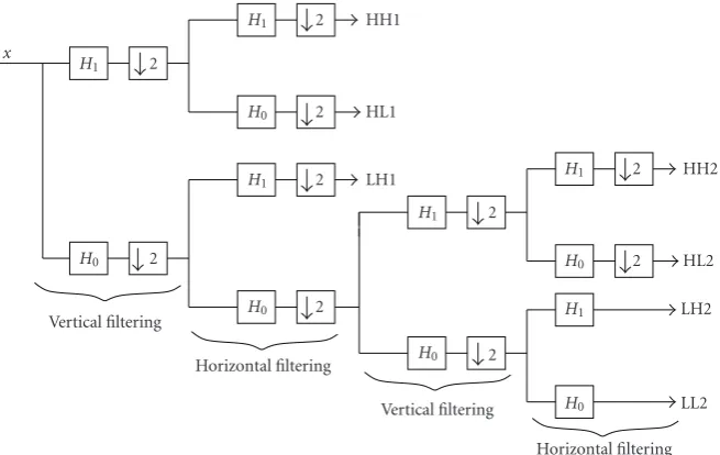
In this section, we consider an application of the presented decoding algorithm to an image coding system with a tree-structured subband signal decomposition shown inFigure 4. In each stage, anN = 2-channel biorthogonal 9/7 wavelet filter bank is employed.
The redundant signal representation is obtained by re-moving the downsamplers in the last horizontal filtering stage. Therefore, the signal in the first two subbands is pro-tected by the OFB code with (N,K)=(2, 1). The generator and parity check matrices of an OFB are given byE(z) =
[H0(z) H1(z)]T andP(z)=[H1(z) −H0(z)], whereH0(z)
andH1(z) are theztransforms of the two-channel wavelet filter bank impulse responses.
We assume that the oversampling is introduced in the last horizontal filtering stage, whereas VLC/FLC coding is ap-plied on the columns of the 2D subband representation of an image. The JSC codeword is depicted inFigure 5. In the case of the system with a VLC, this kind of interleaving pre-vents bursty impulse errors at the output of the entropy de-coder. The interleaving also facilitates iterative decoding of the OFB-FLC chain.
All the results are obtained for the gray scale [512×512] Lena image. The Markov model parameters are estimated by simulation. The parameters EandT are set toE = 5 and T =5. The number of quantization levels in subbands LL2, LH2, HL2, HH2, LH1, HL1, and HH1 is 64, 16, 4, 4, 2, 2, and 2, respectively.
Tables1and2show the performance of various decod-ing algorithms in terms of the mean-square error (MSE), the probability of detectionPd, and the probability of a false
alarmPf. The probability of detection is the probability that
x
H0 H1
2 2
Vertical filtering H0
H0
H1 H1
2 2
2 2
HL1
LH1 HH1
Horizontal filtering H0
H1
2 2
Vertical filtering H0 H1 H0 H1
2 2
LL2 LH2 HL2 HH2
Horizontal filtering Figure4: Structure of an OFB.
Entropy-encoded sequence
OFB-encoded sequence
Coefficient in subb. LL2 Coefficient in subb. LH2
Figure5: JSC codeword.
in the absence of channel noise is 43.3804. The probabil-ities of impulse errors at the output of a VLC decoder in the first two subbands arepLL2=0.0053 andpLH2=0.0077 for Eb/N0=5 dB, and pLL2=0.0116 and pLH2=0.0182
for Eb/N0=4 dB. The impulse-to-quantization noise
ra-tio in the first two subbands are IQRLL2=23.54 dB and IQRLH2=16.4 dB forEb/N0=5 dB, and IQRLL2=24.12 dB and IQRLH2=16.6 dB forEb/N0=4 dB.
Table 2shows the results in the system with an FLC. The MSE in the absence of channel noise is 21.8339. The prob-abilities of impulse errors at the output of FLC decoders in the first two subbands arepLL2 =0.0055 and pLH2=0.0067 forEb/N0=6 dB, andpLL2 =0.0282 andpLH2=0.0344 for
Eb/N0=4 dB. The impulse-to-quantization noise ratios are
IQRLL2=24.9965 dB and IQRLH2=14.8449 dB forEb/N0=
6 dB, and IQRLL2 = 25.5188 dB andIRQLH2 = 14.7 dB for Eb/N0=4 dB. We assume natural binary index assignment.
From Tables1and2, we can see that introducing the soft information in the localization procedure of the syndrome decoding algorithm significantly improves the probability of a detection. In the system with an FLC code, the probability of a false alarm is decreased as well. In the system with a VLC code, the probability of a false alarm is decreased in the subband LL2 where the IQR is high. However, in the LH2 subband where the IQR is low, utilizing the soft information can worsen the probability of a false alarm. In both systems, the MSE performance of Algorithms A and B is similar.
The peak signal-to-noise (PSNR) improvement due to OFB syndrome decoding at Eb/N0 = 4 dB is 0.75 dB for
the system with an FLC and 0.6 dB for the system with a VLC. We have assumed that the entropy decoders perfectly know the Markov model parameters. In this case, the SISO entropy decoding performs very well, that is, the IQR is small. The possible improvement by using a syndrome decoding algorithm is therefore small. For example, in the system with the FLC, the maximum possible PSNR gain due to syndrome decoding is less than 1.18 dB atEb/N0 = 4 dB
and less than 0.24 dB atEb/N0=6 dB. As the other extreme,
we consider a system with the FLC and entropy decoding which does not make use of the Markov property of the source symbols in the first two subbands. For this example, the MSE forEb/N0 = 6 dB in the system with and without
syndrome decoding is 22.87847 and 40.411473.
Figures6 and7show the reconstructed image without and with syndrome decoding for this example.
Figure 8shows the MSE versusEb/Nofor the first and the
Table1: Performance of the syndrome decoding algorithm in the system with a VLC.
MSE PLL2
d PLH2d PLL2f PLH2f Alg. Eb/N0
44.6844 0.4298 0.4006 0.0004 0.0006 A 5 dB
44.4559 0.5516 0.5370 0.0002 0.0013 B 5 dB
48.2196 — — — — PR 5 dB
48.7849 0.3978 0.3218 0.0011 0.0014 A 4 dB
48.1248 0.4851 0.4046 0.0007 0.0027 B 4 dB
55.3454 — — — — PR 4 dB
Table2: Performance of the syndrome decoding algorithm in the system with an FLC.
MSE PLL2
d PLH2d PLL2f PLH2f Alg. Eb/N0
21.9933 0.4981 0.2349 0.0006 0.0055 A 6 dB
21.9697 0.6418 0.3399 0.0005 0.0031 B 6 dB
23.0284 — — — — PR 6 dB
24.2307 0.4231 0.1981 0.0015 0.0051 A 4 dB
24.0243 0.5124 0.2533 0.0010 0.0037 B 4 dB
28.7464 — — — — PR 4 dB
Figure6: Reconstructed image, no syndrome decoding.
Figure7: Reconstructed image after syndrome decoding.
3 4 5
Eb/N0
22 24 26 28 30 32 34 36
MSE
Pseudoinverse receiver First iteration
Fourth iteration Bound
Figure8: Performance of the iterative decoding of the OFB-FLC chain.
shown. From this figure, we can see that iterative decoding reduces the MSE. However, at 3 dB, there is still a significant gap between the performance in the fourth iteration and the performance of the system with no impulse errors in the first two subbands.
8. CONCLUSIONS
improve the error localization procedure. An empirical algo-rithm for the iterative decoding of the FLC-OFB chain has been presented. The performance of the various decoding al-gorithms has been tested for the image compression system with a wavelet-based signal decomposition.
ACKNOWLEDGMENT
A part of this work has been presented in the EUSIPCO ’04 and GLOBECOM ’04 conferences.
REFERENCES
[1] G. R. Redinbo, “Decoding real block codes: activity detection Wiener estimation,”IEEE Transactions on Information Theory, vol. 46, no. 2, pp. 609–623, 2000.
[2] J. Wolf, “Redundancy, the discrete Fourier transform, and im-pulse noise cancellation,”IEEE Transactions on Communica-tions, vol. 31, no. 3, pp. 458–461, 1983.
[3] J.-L. Wu and J. Shiu, “Discrete cosine transform in error con-trol coding,”IEEE Transactions on Communications, vol. 43, no. 5, pp. 1857–1861, 1995.
[4] V. K. Goyal, J. Kovacevic, and M. Vetterli, “Quantized frame expansions as source-channel codes for erasure channels,” in Proceedings of Data Compression Conference (DCC ’99), pp. 326–335, Snowbird, Utah, USA, March 1999.
[5] G. Rath and C. Guillemot, “Performance analysis and recur-sive syndrome decoding of DFT codes for bursty erasure re-covery,”IEEE Transactions on Signal Processing, vol. 51, no. 5, pp. 1335–1350, 2003.
[6] G. Rath and C. Guillemot, “Frame-theoretic analysis of DFT codes with erasures,”IEEE Transactions on Signal Processing, vol. 52, no. 2, pp. 447–460, 2004.
[7] F. Marvasti, M. Hasan, M. Echhart, and S. Talebi, “Efficient al-gorithms for burst error recovery using FFT and other trans-form kernels,”IEEE Transactions on Signal Processing, vol. 47, no. 4, pp. 1065–1075, 1999.
[8] T. G. Marshall Jr., “Coding of real-number sequences for error correction: a digital signal processing problem,”IEEE Journal on Selected Areas in Communications, vol. 2, no. 2, pp. 381– 392, 1984.
[9] R. E. Blahut,Algebraic Methods for Signal Processing and Com-munications Coding, Springer, New York, NY, USA, 1992. [10] S. Mehrotra and P. A. Chou, “On optimal frame expansions
for multiple description quantization,” inProceedings of IEEE International Symposium on Information Theory (ISIT ’00), pp. 176–176, Sorrento, Italy, June 2000.
[11] G. Rath and C. Guillemot, “Characterization of a class of er-ror correcting frames and their application to image transmis-sion,” inProceedings of Picture Coding Symposium, Saint-Malo, France, April 2003.
[12] G. Rath and C. Guillemot, “Subspace algorithms for error lo-calization with DFT codes,” inProceedings of IEEE Interna-tional Conference on Acoustics, Speech, and Signal Processing (ICASSP ’03), vol. 4, pp. 257–260, Hong Kong, China, April 2003.
[13] A. Gabay, O. Rioul, and P. Duhamel, “Joint source-channel coding using structured oversampled filters banks applied to image transmission,” in Proceedings of IEEE Interna-tional Conference on Acoustics, Speech, and Signal Processing (ICASSP ’01), vol. 4, pp. 2581–2584, Salt Lake City, Utah, USA, May 2001.
[14] J. Kovacevic, P. L. Dragotti, and V. K. Goyal, “Filter bank frame expansions with erasures,”IEEE Transactions on Information Theory, vol. 48, no. 6, pp. 1439–1450, 2002.
[15] P. L. Dragotti, S. D. Servetto, and M. Vetterli, “Optimal filter banks for multiple description coding: analysis and synthesis,” IEEE Transactions on Information Theory, vol. 48, no. 7, pp. 2036–2052, 2002.
[16] P. L. Dragotti, J. Kovacevic, and V. K. Goyal, “Quantized over-sampled filter banks with erasures,” in Proceedings of Data Compression Conference (DCC ’01), pp. 173–182, Snowbird, Utah, USA, March 2001.
[17] R. Motwani and C. Guillemot, “Tree-structured oversampled filter banks as joint source-channel codes: application to im-age transmission over erasure channels,”IEEE Transactions on Signal Processing, vol. 52, no. 9, pp. 2584–2599, 2004. [18] G. R. Redinbo, “Decoding real-number convolutional codes:
change detection, Kalman estimation,”IEEE Transactions on Information Theory, vol. 43, no. 6, pp. 1864–1876, 1997. [19] J. C. Chiang, M. Kieffer, and P. Duhamel, “Oversampled filter
banks seen as channel codes: impulse noise correction,” in Pro-ceedings of IEEE International Conference on Acoustics, Speech, and Signal Processing (ICASSP ’03), vol. 4, pp. 249–252, Hong Kong, April 2003.
[20] H. L. Van Trees,Detection, Estimation, and Modulation Theory, John Wiley & Sons, New York, NY, USA, 1968.
[21] H. B¨olcskei and F. Hlawatsch, “Oversampled filter banks: opti-mal noise shaping, design freedom, and noise analysis,” in Pro-ceedings of IEEE International Conference on Acoustics, Speech, and Signal Processing (ICASSP ’97), vol. 3, pp. 2453–2456, Mu-nich, Germany, April 1997.
[22] S. Weiss, “On the design of oversampled filter banks for chan-nel coding,” inProceedings of 12th European Signal Processing Conference, pp. 885–888, Vienna, Austria, September 2004. [23] Z. Cvetkovic and M. Vetterli, “Oversampled filter banks,”IEEE
Transactions on Signal Processing, vol. 46, no. 5, pp. 1245–1255, 1998.
[24] P. P. Vaidyanathan, Multirate Systems and Filter Banks, Prentice-Hall, Englewood Cliffs, NJ, USA, 1993.
[25] A. Guyader, E. Fabre, C. Guillemot, and M. Robert, “Joint source-channel turbo decoding of entropy-coded sources,” IEEE Journal on Selected Areas in Communications, vol. 19, no. 9, pp. 1680–1696, 2001.
[26] L. Bahl, J. Cocke, F. Jelinek, and J. Raviv, “Optimal decoding of linear codes for minimizing symbol error rate,”IEEE Transac-tions on Information Theory, vol. 20, no. 2, pp. 284–287, 1974. [27] R. Bauer and J. Hagenauer, “Iterative source/channel decoding based on a trellis representation for variable length codes,” in Proceedings of IEEE International Symposium on Information Theory (ISIT ’00), pp. 238–238, Sorrento, Italy, June 2000. [28] C. Weidmann and P. Siohan, “D´ecodage conjoint
source-canal avec estimation en ligne de la sourc,” in Proceedings of COmpression et REpr´esentation des Signaux Audiovisuels (CORESA ’03), pp. 105–108, Lyon, France, January 2003.
Christine Guillemotis currently ‘Directeur de Recherche’ at INRIA, in charge of a re-search group dealing with image model-ing, processmodel-ing, and video communication. She holds a Ph.D. degree from ENST ( ´Ecole Nationale Sup´erieure des T´el´ecommunica-tions), Paris. From 1985 to October 1997, she has been with France T´el´ecom/CNET, where she has been involved in various projects in the domain of coding for TV,