Volume 2006, Article ID 39297, Pages1–12 DOI 10.1155/ASP/2006/39297
From MIMO-OFDM Algorithms to a Real-Time Wireless
Prototype: A Systematic Matlab-to-Hardware Design Flow
Jan-Willem Weijers, Veerle Derudder, Sven Janssens, Frederik Petr ´e, and Andr ´e Bourdoux
Wireless Research Group, Interuniversity MicroElectronics Center (IMEC), Kapeldreef 75, B-3001 Leuven, Belgium
Received 22 December 2004; Revised 4 April 2005; Accepted 7 April 2005
To assess the performance of forthcoming 4th generation wireless local area networks, the algorithmic functionality is usually modelled using a high-level mathematical software package, for instance, Matlab. In order to validate the modelling assumptions against the real physical world, the high-level functional model needs to be translated into a prototype. A systematic system design methodology proves very valuable, since it avoids, or, at least reduces, numerous design iterations. In this paper, we propose a novel Matlab-to-hardware design flow, which allows to map the algorithmic functionality onto the target prototyping platform in a systematic and reproducible way. The proposed design flow is partly manual and partly tool assisted. It is shown that the proposed design flow allows to use the same testbench throughout the whole design flow and avoids time-consuming and error-prone intermediate translation steps.
Copyright © 2006 Hindawi Publishing Corporation. All rights reserved.
1. INTRODUCTION
Fourth generation high-throughput (HT) wireless local area networks (WLANs), which are currently being standard-ized in the IEEE 802.11n Working Group [1], aim for higher data rates (well beyond 100 Mbps effective through-put at the medium access control (MAC) service access point (SAP)), larger range, and better quality-of-service (QoS), compared to existing IEEE 802.11a/g type of WLANs. To meet these ambitious targets, it is now widely agreed upon that both the physical (PHY) and the MAC layer of these HT-WLANs will capitalize on so-called input multiple-output (MIMO) orthogonal frequency-division multiplex-ing (OFDM) communication technology [2]. On the one hand, MIMO techniques, which deploy multiple antennas at both ends of the wireless link, allow to significantly in-crease the spectral efficiency (and, hence, the data rate), and to significantly improve the performance (and, hence, the QoS and/or the range), compared to their single-antenna counterparts [3–5]. On the other hand, OFDM modulation enables low-complexity frequency-domain processing over the highly frequency-selective indoor propagation channel [6–8].
Several types of MIMO-OFDM processing can be en-visioned, depending on where the processing is performed: transmit (TX-only) processing, receive (RX-only) processing and joint TX-RX processing. In either case, defining, opti-mizing, and verifying the selected digital signal processing
(DSP) algorithms for the WLAN system under consideration almost always require the modeling and the simulation of the complete system functionality using a mathematical soft-ware package like, for instance, Matlab. All aspects like auto-matic gain control (AGC), phase noise, clock frequency off-set (CFO), and their impact on synchronization and tracking need to be taken into account. Once the system functionality achieves the expected end-to-end performance, it needs to be translated into a prototype, in order to validate the mod-eling assumptions against the real physical world. However, this translation process consists of four major steps. First, a hardware architecture needs to be defined. Second, float-ing-point numbers need to be quantized. Third, timing needs to be added. Finally, interfaces to the MAC and higher software layers need to be defined. Meanwhile, constraints like power consumption, hardware cost, design time, and, most importantly, real-time operation need to be taken into account. Unfortunately, these translation steps have not been automated up till now. A lot of human intervention is still needed, which will inevitably introduce errors. Hence, a sys-tematic design flow is needed to detect these errors as early as possible. Even when using field-programmable gate arrays (FPGAs) as a target prototyping platform, a first-time-right design methodology is very valuable, since it prevents nu-merous design iterations and bug fixes, which would lead to unacceptable project delays.
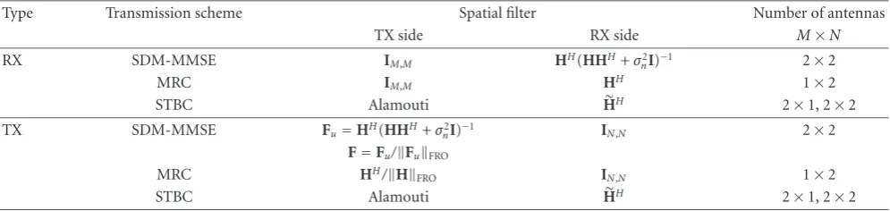
Table1: Implemented MIMO schemes. (H is the virtual matrix corresponding to the STBC precoding,HFROis the Frobenius norm of H.)
Type Transmission scheme Spatial filter Number of antennas
TX side RX side M×N
RX SDM-MMSE IM,M HH(HHH+σn2I)−1 2×2
MRC IM,M HH 1×2
STBC Alamouti HH 2×1, 2×2
TX SDM-MMSE Fu=HH(HHH+σ2
nI)−1 IN,N 2×2
F=Fu/FuFRO
MRC HH/HFRO IN,N 1×2
STBC Alamouti HH 2×1, 2×2
prototype. The first approach relies on Simulink to rewrite the Matlab model into a quantized register-transfer-level (RTL) Matlab model by means of schematic entry [9]. This RTL-Matlab model is then automatically translated into a very-high-speed hardware description language (VHDL) model. The second approach rewrites the Matlab model into a C++-based hardware description language, like, for in-stance, SystemC [10]. Using a variety of commercial tools, the obtained model can then be simulated, refined, and syn-thesized. A major disadvantage, which is common to both methodologies, is the need for completely rewriting the Mat-lab model into an RTL model. The rationale behind the work in this paper is the simple observation that this rewriting step is needed anyway, so why not translating the functional model directly into VHDL, instead of going through very time-consuming intermediate translation steps.
The Matlab-to-prototype translation is broken into dis-tinct subproblems. For each of these subproblems, the most appropriate design flow, tool assistance, and languages are given. The same testbench is used throughout the whole de-sign cycle, which allows for example to simulate the effect of front-end impairments on the RT-level description. Thanks to the bit-identical behavior from Matlab to prototype, mea-sured data can easily be evaluated with the Matlab model. Even mixing Matlab calculations and real-time prototype operation is possible, for example calculation of compensa-tion values for front-end drift.
The paper is organized as follows.Section 2describes the complete end-to-end system model, including a detailed sys-tem architecture for the access point functionality.Section 3
introduces the real-time prototyping environment.Section 4
explains our proposed system design methodology, which al-lows to map the available system functionality on the target prototyping platform in a systematic and reproducible way. Finally,Section 5summarizes our approach and formulates our major conclusions.
2. SYSTEM ARCHITECTURE
Our target was to implement both MIMO schemes with receiver processing (MIMO-RX) and MIMO schemes with transmitter processing (MIMO-TX), see [11,12]. Spatial di-vision multiplexing (SDM) [13], maximum ratio combining (MRC) [14,15], and space-time block coding (STBC) [16]
are supported at both sides. OFDM processing with MIMO processing per subcarrier is used as a modulation technique to mitigate the effects of the highly frequency-selective in-door propagation channel. These physical devices are very close to those currently discussed in the IEEE 802.11n Stan-dardization Committee.
Table 1 sumarizes the various MIMO transmission
schemes that were implemented, together with the pre- and postfilter used and the number of TX and RX antennas.1An important point is that in the case of TX processing (SDM, MRC), no channel state information (CSI) is theoretically needed at the receiver because no spatial processing needs to be applied. In practice, per-stream channel estimation and equalization are still needed in order to scale and rotate the received constellations because of transceiver effects such as AGC, residual frequency offsets, phase noise, and so forth. Figures1and2show the functional block diagrams of these two transmission schemes.
The starting point for the implementation is the floating-point Matlab model of the MIMO schemes. The Matlab model allows to accurately simulate the various MIMO transmission schemes. In addition, a key feature of our Mat-lab model is that front-end nonidealities are also included in the model. The reason is twofold: first, the baseband sig-nal processing can to some extent mitigate certain front-end effects (carrier frequency offsets, phase noise, etc.). Second, this allows to predict the performance of the digital modem together with the analog frontend, and to possibly provide early front-end specifications to the front-end designers. The overall Matlab model that enables to perform these mixed-signal simulations is shown inFigure 3.
We will focus on the baseband processing blocks of
Figure 3. These blocks run at 20 MHz and perform the DSP operations needed for MIMO-OFDM. The demonstra-tor will be implemented to prove the correctness of these MIMO-OFDM algorithms. Both the user terminal and the
Preamble (STS) for coarse synchronization.
CoarseΔf andΔt estimation
Antenna #1 Input signal from down-sampling
filters (20 Msps complex) Antenna #2
Payload CP
CP
S/P
S/P
FineΔf andΔtest
Preamble (LTS)
FineΔf andΔtest
Correct preamble
Correct preamble
Chan. estim.
To tracking init.
Chan. estim.
H
Δffine
To tracking init.
F
Coeff. calc.
FFT
FFT
Tracking MMSESTBC MRC
Demap-ping
Bits to decoder
Figure1: Functional block diagram of the MIMO-RX.
Estimated channel
H
Front-end calibr.
Transceiver calibration
data
Coeff. calc.
F
Frequency-domain preamble
Time-domain preamble
Input bit streams
Mapper
Mapper
MUX
MUX TX pre-filter
IFFT
IFFT P/S
P/S CP
CP
MUX
MUX
Antenna #1
Output signal to upsampling filters (20 Msps, complex)
Antenna #2
Not used if no TX processing
2 SISO OFDM modems
Figure2: Functional block diagram of the MIMO-TX.
base station operations will be implemented. Where possi-ble, hardware will be reused between uplink and downlink and between algorithms. Transmit, receive, and initialization operations are started under control of MAC layer software which will not be treated in this paper. In total, 1500 lines of Matlab code need to be implemented.
3. PLATFORM ARCHITECTURE
The real-time demonstrator will use IMECs Picard testbed [17]. A Picard system consists of a PCI backplane, a general-purpose processor board, one or more front-end boards each supporting one antenna, and one or more baseband pro-cessing boards, seeFigure 4. Each baseband processing board
contains two Xilinx Virtex II 6000 FPGAs [18], seeFigure 5. Each FPGA contains 144 multipliers of 18-by-18 bit, 144 RAM blocks of 18 kb and 33792 “slices.” A slice contains 2 flipflops, 216- bit-SRAM-based lookup tables which imple-ment any 4-input combinatorial function, and several gates to cascade slices.
De-mux
Symb. map.
Symb. map.
. . .
MMSE MRC STBC SISO
(per sub-carrier)
OFDM mod.
OFDM mod.
. . .
N
N
CNQ
CNQ I-Q
I-Q PHN
PHN PA
PA . . .
Nbits,
μ Δε,ϕ
Integr. phase noise, BW, floor P1dB
Front-end model
Timing, freq. offsets
H
AWGN SNR
Nbits,
μ Δε,ϕ
Integr. phase noise, BW, floor
De-mux
Symb. demap.
Symb. demap.
. . .
MMSE MRC STBC SISO (per
sub-carrier)
Tracking
Coeff. calc.
Chan. estim.
Coarse/ fine synch. OFDM dem.
OFDM dem.
. . .
Preamble
Front-end model . . .
N
N
CNQ
CNQ I-Q
I-Q PHN
PHN
Figure3: Matlab MIMO model including TX and RX processing and front-end effects.
reduce the hardware usage. However, this would require a more “user-assisted” routing and/or a more complex mul-tiplexing of resources.
The most critical hardware resources are the number of multipliers needed to implement the baseband processing, and the hardware size. The hardware size, expressed as the number of slices, together with the number of multipliers, drives the division of the logic over the 2 FPGAs. Early es-timates of these numbers need to be communicated to the algorithm designers which can opt for a different algorithm if the hardware size of the current algorithm is too big. The MIMO-OFDM base station logic has all spatial filter calcula-tions ofTable 1in one FPGA, all other logic is located in the other FPGA, seeFigure 6. Tables2and3give the sizes of each functional block.
4. MATLAB-TO-HARDWARE DESIGN METHODOLOGY
Translating a Matlab model to VHDL in a systematic and re-producable way requires the addition of a lot of details to the
model and, if necessary, choosing for a different implementa-tion of an algorithm. As this task is not automated, bugs are inevitably introduced. It is of utmost importance that after each step, the refined model is simulated and compared with the original model. Using the same testbench or, at least, the same input and output values during the whole design cycle guarantees that the prototype will behave exactly the same as the original Matlab model.
Figure4: Picard prototyping system.
To and from frontends
Initialization FPGA
Datapath FPGA
Forward error coder/ decoder PCI interface
Figure5: Picard board.
The design flow is drawn in Figure 7. Following tasks will be handled in more detail in the next sections: hardware-architecture development, fixed-point refinement, system integration, and RTL design. These tasks require a lot of human intervention, which will inevitably introduce errors. After each task, extensive simulations are needed to avoid unwanted differences in performance. Using the same testbench during the whole design cycle significantly reduces the debugging effort. The choice of algorithm implementa-tion and the fixed-point refinement are executed in Matlab. This allows the reuse of the original testbench on which the algorithms were developed. Defining signals which exist both in Matlab and in VHDL allows to compare the RTL design with the refined Matlab model.
This section is organized as follows. Section 4.1 in-troduces the hardware-architecture definition step, while
Section 4.2 explains the Matlab fixed-point and hardware
Table2: FPGA datapath hardware size.
Entity 18×18 mult. 18 kbit RAM kslices
Mapper + StbcTx — 3 0.9
Demapper 1 3 1.2
SdmaProc: DlSdma 6 — 1.4
SdmaProc: STP 6 1 0.9
HFF storage — 6 0.9
Tracking + WaitHFIFO 3 4 3.0
ZeroProc — 1 0.3
C addition — 1 0.3
FFTIFFT 8 — 2.3
Guard — 1 0.5
Sync 34 3 3.0
MasterControl — 1 1.0
MpSlave — — 0.3
ConB2A — — 0.1
ChEst 36 12 7.9
NoiseEst 2 1 0.5
Total 96 37 24.5
Resources used 67% 27% 75%
Table3: FPGA init hardware size without PCI or processor. Entity 18×18 mult. 18 kbit RAM kslices
FeComp 6 — 1.0
HStorage — 4 0.8
MMSE 44 — 5.8
HFnorm 8 1 2.0
ConA2B — — 0.2
SlaveControl — 1 0.3
MpMaster — — 0.2
Total 58 6 10.3
Resources used (%) 40% 4% 31%
refinement step.Section 4.3describes the system integration step, whileSection 4.4reviews the RTL design step. Finally,
Section 4.5explores the possibilities for design reuse offered
by our design flow.
4.1. HW-architecture development
For this MIMO-OFDM application, a quick top-level com-plexity assessment has shown that general-purpose CPUs or DSP processors are either too slow or consume too much power. FPGAs were found to provide sufficient processing power while being especially suited for prototype develop-ment. If necessary, the RTL code can be resynthesized for an ASIC, although more thorough optimizations should be con-sidered in that case.
User data
MapDemap
Mapper
STBC-Tx
Demapper
17,15
18,13
/4=
18,15
SdmaProc
DISdma
Shared
Space-time processing STBC-Rx
17,11
18,13
17,11
17,15 Tracking
17,15
W
aitHFIFO
10,9
ZeroProc
Zero-insert
Zero-delete
RAM
10,9
C-sy
mbols
18,13
10,5/16=
10,9
FFTIFFT
IFFT
Shared
FFT
10,9
10,9∗16=
18,13
Guard
Guard-insert
Guard-delete
RAM
10,9
10,9
Antenna data
Sync
SyncS
SyncR
10,9
HFF storage RAM
17,11 18,15/2= 17,15
Caddition RAM
C-Rx C-Rx 11,9
ChEst NoiseEst
18,15 H C-tx
15,15
No
is
e
ConB2A FPGA datapath
ConA2B FPGA init
Global control
MasterControl
SlaveControl
MpInterf
Mp slave
Mp master
PCI-interface + processor Noise
15,15
17,11
HFnorm
17,11
MMSE
17,13or17,15
Fecomp Hstorage RAM
18,15/2= 17,15
17,15∗4= 17,13
Figure6: Base station functionality.
operations and matrix inversions. If possible, a different algorithm or a simplification of the algorithm should be used to avoid these operations. In general, the Matlab code should only use operations, for which a hardware equivalent is avail-able. The number of operations (easily found by profiling), divided by the number of hardware resources, defines the du-ration of the calculations. If this dudu-ration is too long, more hardware resources are needed or the algorithm needs to be simplified to reduce the number of operations.
Data dependencies dictate the amount of memory needed. These memories have an impact on the power con-sumption and the latency of the calculations. Three exam-ples are (I)FFT operations where the order of the output data is bit-reversed, guard insertion, and datapaths which split in parallel branches with different latencies and which join again. In general, these data dependencies are hard to find in the Matlab code, because they are not explicitly modeled. Memory analysis tools like, for example, from PowerEscape [19], could help, but in general they take C-code as input. If translation of the Matlab code to C-code is a too big ef-fort, a manual “pen-and-paper” analysis of the Matlab code is needed.
VirtexII FPGAs contain block RAMs of 18 kb. Except for very small memories, each memory is mapped on one or more of these block RAMs. For a prototype, no effort needs to be spent on optimizing the memories to a size of less than 18 kb. For high-volume products, more effort is needed to reduce the memory requirements.
The MIMO-OFDM base station which serves as an ex-ample in this document is dominated by the amount of multiplications. Approximately, 150 18×18 bit multipliers are needed. Thanks to the early hardware-architecture ex-ploration, the algorithms could be changed to reduce the number of dividers to 3. Matrix inversion is rewritten and now uses the LDLHdecomposition because of the properties (Hermiticity) of the matrix which needs to be inverted. All MIMO algorithms described inSection 2could be mapped on the same hardware, spread over 2 FPGAs.
Matlab floating-point model
HW-architecture definition, memory insertion Size, latency, speed estimation Size, latency, and speed
requirements
Compare
Too big or too slow
Matlab fixed-point refinement, HW datapath refinement
Compare
Performance loss too big System integration:
(i) interface definition
(ii) toplevel controller intelligence
RTL design
Compare
bit by bit Bit errors
Standard synthesis and back-end flow
Netlist
Figure7: Design flow for MIMO-OFDM implementation.
implementation-friendly algorithms can be easily tested with the same Matlab testbenches as used for the original algo-rithm development.
In general, the functionality of the floating-point model is easily split into groups of operations which belong to-gether. Some examples are (I)FFT, tracking, channel estima-tion, power normalization. Each group of operations will be implemented as a VHDL entity, possibly with many more subhierarchies. Each group of operations will be called a “top-level entity” in this paper. The top-level entities are shown inFigure 6. They are connected by “top-level signals.” These top-level signals will become the checkpoints for com-paring Matlab and RT-level simulations.
4.2. Matlab fixed-point and hardware refinement
Fixed-point arithmetic is prefered over floating-point arith-metic due to its smaller size after translation to hardware. In general, algorithm development in Matlab is done in float-ing point; this is the floatfloat-ing-point model. After completion of the algorithm, it needs to be translated into a fixed-point representation: the fixed-point model.Figure 8shows the de-tailed design flow for the quantization and hardware refine-ment step.
The problem of converting the floating-point model to a fixed-point model needs to be solved independently of the language (Matlab, Simulink, C, VHDL). As will be shown in the next paragraphs, simulation speed and integration with the floating point model are important. For this rea-son, we prefer to perform this task in Matlab. An additional advantage of the availability of a fixed-point Matlab model is the possibility of cosimulation of floating-point and fixed-point models. The floating-fixed-point front-end model with all its impairments like phase noise, clock frequncy offset (CFO), automatic gain control can be simulated together with the bit-true representation of what later will become the proto-type which implements the baseband processing. Stimuli are generated by a floating-point model of 2 user terminals. Per transmit-receive antenna pair, a Hiperlan2 channel type A is used. An antenna correlation factor of 0.2 is applied both for transmit and receive. The resulting signals are applied to the frontend of the receiver.
Floating-point model
Set maximum performance degradation
Toplevel quantization
Simulate Too much degradation
Implementation choices Quantize internal signals of a toplevel entity
Simulate
All top entities quantized?
Simulate
Fixed-point model Too much degradation
or too much hardware
Still more variables need to be quantized
Too much degradation or too much hardware
Figure8: Design flow for MIMO-OFDM quantization.
important that this test executes as fast as possible, because it will be run a lot of times. A faster test with less accuracy could also be used. In that case, the full accuracy test is kept as a final check. A faster test could be a maximum BER degra-dation of 10−4at a typical signal-to-noise ratio.
Starting point for the quantization is a first simulation, which reveals the amplitude of the signals. This gives an up-per bound for the number of bits before the comma. For each signal, the standard deviation of the difference of the value during a floating-point simulation and the value dur-ing a simulation with partly quantized signals gives an upper bound of the required number of bits after the comma [20]. In general, these upper bounds are pessimistic. Applying sat-uration and rounding allows to reduce the required number of bits, although these operations require additional hard-ware. Especially, the quantization of feedback loops and ac-cumulations need manual intervention. Typical for MIMO systems are the signals at the antenna, which suffer from a high peak-to-average power ratio (PAPR). Saturating the highest peaks can reduce the required number of bits.
The maximum allowed performance loss should be con-sidered as an “error budget.” Almost each signal, which is quantized, consumes a part of the budget. A big part of the budget can be distributed over the various top-level signals proportional to the hardware (or dollar) cost of the func-tions, which are influenced by the quantization. For example,
a fast division operator which accepts one input per clock cy-cle is an expensive hardware operation. A division which is one bit longer consumes a lot more gates. For that reason, it is recommended to spend a larger portion of the perfor-mance decrease budget to use less bits for those signals which influence the divider word length.
Quantization can cost a lot of manpower. Some trade-offs are needed. For high-volume products, the savings in hardware cost are worth the additional manpower cost of fur-ther optimizing the quantization. On the ofur-ther hand, if FP-GAs with dedicated multipliers are used, it is not necessary to reduce the quantization of the signals which need to be multiplied to a number of bits less than the multiplier size. In case of Xilinx VirtexII FPGAs, the multipliers are 18-by-18 bit and do not allow subword parallellism. In the multi-plication intensive MIMO-OFDM example we use through-out this paper, the first attempt of quantization of all sig-nals is therefore 18 bits. The same FPGA family also supports dedicated RAMs which are 18-or-36 bit wide. Data stored in these RAMs is allowed to be 18-bit wide without additional hardware cost. A tradeoffof accuracy versus hardware size is possible for the complex multiplier. If the signals to be mul-tiplied are 17 bits or less, the complex multiplication can be implemented with only 3 real multiplications and 5 real ad-ditions instead of 4 real multiplications and 2 real adad-ditions. Signals which are not only multiplied and stored in RAM but which are also added and stored in flipflops should be reduced in size when possible in order to save FPGA hard-ware. Divisions need special attention because in general, they require 20 bits or more and require a lot of hardware for a reasonably fast implementation. On the other hand, the square root operation requires a relatively small amount of hardware and reduces the word length with a factor 2.
Quantization of the top-level signals is performed first. One signal at a time is quantized. Each attempt needs to be simulated. Two values need to be defined: the number of bits and the position of the comma. After all top-level sig-nals are quantized, the top-level entities are quantized. Each top-level entity is assigned a part of the rest of the perfor-mance decrease budget, based on the hardware cost function. Quantizing the internal signals of a top-level entity is almost independent of the internal quantization of other top-level entities. For this reason, the internal quantization of top-level entities can be done in parallel by several designers. Again, the quantization values which are not easily derived from al-ready quantized signals need to be checked by simulation.
Quantization in Matlab is performed using function calls. In Simulink, quantization blocks are dragged and dropped on signals. In either case, it is very important that identical functions are available for hardware implementa-tion. Each top-level entity which is converted to hardware needs to be simulated and compared with the fixed-point Matlab model. The two design representations should be identical at the bit level.
User data FIFO Downlink datapath Serial interface
To front-ends
User data FIFO
Uplink datapath interfaceSerial From front-ends
Controller
Initialization
(i)UL channel estimation (ii)DL precompensation
PCI
-Start/stop -Parameters -Status -Interrupts
MAC layer software
Modelled in Matlab
Figure9: Interfaces for system integration.
includes the optimizations based on the hardware require-ments. The word lengths are indicated inFigure 6. The first number is the word length, the second number indicates the amount of bits behind the comma. With this internal quan-tization, an SNR degradation of 0.37 dB for MMSE, 0.03 dB for MRC, 0.19 dB for STBC2x1, and 0.31 dB for STBC2x2 is achieved.
4.3. System integration
The Matlab model describes the datapath operations which need to be performed on the antenna or user data. The dat-apath however does not exist in isolation. It has to commu-nicate with sources and sinks of user/antenna data. The dat-apath has to be started, stopped and parameters like modu-lation scheme, algorithm choice, and so forth need to be set. These operations need to be modeled by the hardware devel-opper in cooperation with the software designers. Figure 9
shows these “system interfaces.”
The complexity of these “system interfaces” is one of the factors which need to be taken into account when defining the approach which is followed to convert the Matlab fixed-point model to hardware. We will now discuss the weak and strong points of three possible design flows for system inte-gration.
(1) Simulink provides the designer with a library of com-ponents which have a hardware equivalent. By means of schematic entry, these components are connected. Cosimu-lation with Matlab code and hardware synthesis are straight-forward. Simulink is an option for systems which are not too complex because Matlab and Simulink are oriented to-wards DSP operations, not toto-wards control. Implementa-tion of synthesizable control logic requires schematic entry, sometimes even down to the gate level. The MIMO-OFDM base station with its flexibility in choice of algorithm, parallel datapaths, and shared hardware requires too much control to be easily described in Simulink.
(2) SystemC is situated at the other end of the spec-trum. C and C++ are perfectly suited to implement complex
control strategies. Cosimulation of a SystemC description of the hardware with the MAC layer software is straightforward. Synthesis of SystemC descriptions to gates requires the Sys-temC description to be at RT or behavioral level. The Matlab model needs to be completely rewritten. Using SystemC is an option if there is a lot of interaction between hardware and software (the MAC layer) which need to be simulated. Hardware-software partitioning decisions can be delayed un-til relatively late in the design cycle.
(3) Both Simulink and SystemC require the Matlab fixed-point model to be completely rewritten to an RT-level model. The MIMO-OFDM algorithms needed for our example base station do not need much interaction with the MAC-layer software: once started, the datapath can run almost completely without software interventions. For these rea-sons, an immediate, manual conversion from Matlab fixed point to RTL-VHDL was used. The implementation of the “system interfaces” often can be copied from previous projects, see alsoSection 4.5on IP-reuse.
4.4. RTL design
One important property is still missing in the Matlab fixed-point model: timing. Timing is important to describe for example time multiplexing and the delay of hardware opera-tors. Before hardware synthesis is possible, this information has to be added to the design. We will now discuss the weak and strong points of three possible design flows for RTL im-plementation.
(2) SystemC models are either written at the RT-level or at the behavioral level. SystemC RT-level coding is compara-ble to VHDL RT-level coding. However, in SystemC RT-level, it is more difficult to use Xilinx-specific components. In ad-dition, not all FPGA synthesis tools accept SystemC-RTL as an input language. SystemC behavioral level requires less accurate timing information from the designer. The results however are not always as expected and tuning of the behav-ioral SystemC code is often necessary.
(3) VHDL is a natural language for RTL-level design. In addition reuse of previous designs, which are often written in this language, is no problem.
Verification of the RTL design is very important. Each top-level entity in Matlab needs to be translated to a “bit-identical” RTL model. For SystemC and VHDL RTL designs, the level signals which are input and output of the top-level entities are dumped to files. These files are used as input and expected-output of the simulations of the RTL top-level entities.
It is not sufficient that each top-level entity contains the correct datapath. They also need to correctly interpret the handshaking and data ordering of the entities with which they communicate. Control signals should be generated in time by the “controller” entity of Figure 9. For these rea-sons, integration tests are also needed. Integration tests use the input and expected-output values at the “system inter-faces.”
For a MIMO-OFDM base station like the one which serves as an example in this paper, designing the control and top-level handshaking is a major task. Immediately after the hardware-architecture definition phase, this task can be started. The actual datapath calculations are temporarily re-placed with dummy operations which need the same amount of data and the same amount of time. Using these dummy models, the assumptions on data storage and throughput made during the hardware-architecture definition phase can be tested before the datapath implementation starts. When implementation of the top-level entities starts, the dummy model serves as a specification of the control signals for the designers. This “executable control signal specification” pre-vents major problems during the integration tests described in the previous paragraph.
4.5. IP-reuse
Rewriting a fixed-point Matlab model of a system as complex as a MIMO-OFDM base station to an RTL model may seem a gigantic task. Luckily, not every line of code needs to be written from scratch. In many cases, parts from previous projects can be reused. These “parts” are known as “IP-blocks,” where IP stands for intellectual property. In addi-tion, Xilinx provides a library of IP-cores, known as “Core-gen” [21].
Xilinx-Coregen is an interesting tool for generating IP-blocks ranging from FIFOs to a PCI interface. Some of this IP is licensed, some of it is available for free. The generated IP-blocks make optimal use of the FPGA resources. For compli-cated datapath operators, Coregen is less interesting because
the internal quantization is unknown, which often prevents creating an equivalent model in Matlab.
As already treated in the previous sections, it is impor-tant that the fixed-point Matlab model has a bit-true hard-ware equivalent. A dual library of fixed-point functions is a minimum requirement. To implement the MIMO-OFDM functionality, the following functions are necessary: word-length conversions, saturation, flooring, and rounding. This library might already be available from previous projects and can be reused in future projects.
Other functions which are often needed for MIMO-OFDM applications are (I)FFT, complex multiplication, and the CORDIC-operator.2Writing bit-compatible Matlab and RTL components once and reusing them within and be-tween designs speeds up Matlab quantization and later RTL design. During Matlab quantization, high-level func-tion calls like matrix multiplicafunc-tion need to be expressed in more basic operations: real additions and multiplications. Each basic operation then needs to be quantized. If a bit-compatible complex-multiply-accumulate function is avail-able, the floating-point matrix multiplication only needs to be rewritten in terms of complex-multiply-accumulate func-tion calls with the correct quantizafunc-tion values. The RTL de-sign then calls the same function with the same parameters without the need of testing the internals of the implemented function. Using the tested function of such a bit-true dual library considerably speeds up design time and reduces the risk of errors.
A third type of mathematical functions which need dual bit-true implementations is the division and square root operations. These functions are often needed for MIMO-OFDM implementations. Coregen can generate synchronous implementations. Synopsys/designware library [22] contains asynchronous implementations in which af-terwards some pipeline stages are inserted until the FPGA clock speed is achieved. Knowing the quantization of the in-puts, the output quantization is uniquely defined. This can be modeled in Matlab without knowing the exact internal algorithm of the hardware model. In Matlab, it is sufficient to take the quantized input(s), to perform the square root or division, and to apply the output quantization to the re-sult.
Another type of basic operators exists only in hardware: interfaces between top-level blocks and between the hard-ware and the outside world. These interfaces need to be designed only once and can be reused within or between projects.
The example MIMO-OFDM base station used through-out this paper is implemented in two Xilinx VirtexII 6000 FPGAs and consumes 154 multipliers, 43 block RAMs, and 33792 slices. This does not include interfaces to the rest of the Picard prototyping environment like the PCI interface, the user data buffers, and the small processor. These blocks also fit in the two FPGAs.
5. CONCLUSIONS
A systematic approach to translate Matlab models of MIMO-OFDM algorithms in a real-time wireless proto-type is given in this paper. The translation problem is split into four subproblems: hardware-architecture development, fixed-point refinement, timing, and system integration. For each step, the task is defined and the optimum tools and languages are defined. The baseband processing of a MIMO-OFDM base station has been implemented with success us-ing this approach. Use of the already existus-ing components of IMECs Picard platform allowed us to successfully build a real-time, 5 GHz wireless demonstrator of the hardware of a MIMO-OFDM access point. The physical parameters of the demonstrated MIMO-OFDM access point are very close to those currently being discussed in the IEEE 802.11n Stan-dardization Committee.
REFERENCES
[1] “IEEE 802.11 Homepage,” http://grouper.ieee.org/groups/ 802/11.
[2] G. L. Stuber, J. R. Barry, S. W. McLaughlin, Ye Li, M. A. In-gram, and T. G. Pratt, “Broadband MIMO-OFDM wireless communications,”Proceedings of the IEEE, vol. 92, no. 2, pp. 271–294, 2004.
[3] A. F. Naguib, N. Seshadri, and A. R. Calderbank, “Increasing data rate over wireless channels,”IEEE Signal Processing Mag-azine, vol. 17, no. 3, pp. 76–92, 2000.
[4] D. Gesbert, M. Shafi, D.-S. Shiu, P. J. Smith, and A. Naguib, “From theory to practice: an overview of MIMO space-time coded wireless systems,” IEEE Journal on Selected Areas in Communications, vol. 21, no. 3, pp. 281–302, 2003.
[5] A. J. Paulraj, D. A. Gore, R. U. Nabar, and H. Boelcskei, “An overview of MIMO communications - a key to gigabit wire-less,”Proceedings of the IEEE, vol. 92, no. 2, pp. 198–218, 2004. [6] Z. Wang and G. B. Giannakis, “Wireless multicarrier commu-nications: where Fourier meets Shannon,”IEEE Signal Process-ing Magazine, vol. 17, no. 3, pp. 29–48, 2000.
[7] M. Engels, Ed.,Wireless OFDM Systems: How to Make Them Work?, Kluwer Academic, Boston, Mass, USA, 2002.
[8] A. R. S. Bahai and B. R. Saltzberg,Multi-Carrier Digital Com-munications: Theory and Applications of OFDM, Kluwer Aca-demic, New York, NY, USA, 1999.
[9] “The MathWorks - MATLAB and Simulink for Technical Computing,”http://www.mathworks.com.
[10] “Homepage of the SystemC community,”http://www.systemc. org.
[11] P. Vandenameele,Space Division Multiple Access for Wireless Local Area Networks, Ph.D. thesis, Katholieke Universiteit Leu-ven, LeuLeu-ven, Belgium, October 2000.
[12] S. Thoen,Transmit optimization for OFDM/SDMA-based wire-less local area networks, Ph.D. thesis, Katholieke Universiteit Leuven, Leuven, Belgium, May 2002.
[13] A. J. Paulraj and C. B. Papadias, “Space-time processing for wireless communications,”IEEE Signal Processing Magazine, vol. 14, no. 6, pp. 49–83, 1997.
[14] T. K. Y. Lo, “Maximum ratio transmission,”IEEE Transactions on Communications, vol. 47, no. 10, pp. 1458–1461, 1999. [15] J. H. Winters, J. Salz, and R. D. Gitlin, “The impact of antenna
diversity on the capacity of wireless communication systems,”
IEEE Transactions on Communications, vol. 42, no. 234, pp. 1740–1751, 1994.
[16] S. M. Alamouti, “A simple transmit diversity technique for wireless communications,”IEEE Journal on Selected Areas in Communications, vol. 16, no. 8, pp. 1451–1458, 1998. [17] M. Wouters, T. Huybrechts, R. Huys, S. De Rore, S. Sanders,
and E. Uman, “Picard: platform concepts for prototyping and demonstration of high speed communication systems,” in Pro-ceedings of 13th IEEE Workshop on Rapid System Prototyping (RSP ’02), pp. 166–170, Darmstadt, Germany, July 2002. [18] “Xilinx Home : Products and Services : Silicon Solutions :
Virtex-II Platform FPGAs,”http://www.xilinx.com/products/ silicon solutions/fpgas/virtex/virtex ii platform fpgas/index. htm.
[19] “PowerEscape Architect,” http://www.powerescape.com/ products/architect.php.
[20] R. Cmar, L. Rijnders, P. Schaumont, S. Vernalde, and I. Bolsens, “A methodology and design environment for DSP ASIC fixed point refinement,” inProceedings of Conference on Design, Automation and Test in Europe (DATE ’99), pp. 271– 276, Munich, Germany, March 1999.
[21] “Xilinx Design Tools Center : CORE Generator,”http://www. xilinx.com/xlnx/xebiz/designResources/ip product details. jsp?key=dr dt coregenerator.
[22] “DesignWare Intellectual Property,” http://www.synopsys. com/products/designware/designware.html.
Jan-Willem Weijers was born in 1965 in the Netherlands. He received the degree of Civil Engineer Microelectronics at KULeu-ven, Belgium, in 1989. His thesis work de-scribed the an ASIC implementation of singular value decomposition and was ex-ecuted at Interuniversity MicroElectronics Center (IMEC), Belgium. From 1989 till 1999, he was ASIC Designer at Siemens Atea, Herentals, Belgium. During this time
frame, he fulfilled several periods of employment at Siemens Ger-many (Dusseldorf and Munich). At Siemens, he implemented sev-eral telecom ASICs in VHDL (digital PLLs and controllers of ATM-based data). From 2000 on, he joined IMEC where he designed ASIC architectures to implement DSP algorithms, improved exist-ing XILINX implementations, and did DSP quantizations. Recent projects include the design and test of the control logic for a low-power high-throughput turbo coder and turbo decoder and the de-sign, test, and implementation of the hardware architecture, and control logic of several FPGA-based MIMO-OFDM systems.
Veerle Derudderreceived the M. Eng. de-gree in electrical engineering from Kath-olieke Hogeschool Brugge Oostende, Bel-gium, in 1990. She joined the Interuniver-sity MicroElectronics Center (IMEC), Leu-ven, Belgium in 1990, working on the de-sign of parameterized module generators for DSP applications. In 1995, she became responsible for the ASIC test strategy. She has also been involved in the design of
Sven Janssens received the Electrical En-gineering degree in 2000 at the Univer-sity of Leuven, Belgium. In 2000, he joined the Interuniversity MicroElectronics Center (IMEC), where he worked on the develop-ment of a smart multiple-antenna system. He contributed to the algorithmic explo-ration and the design of the digital hardware for a real-time wireless prototype. His re-search interests include the design of digital communication systems.
Frederik Petr´eis a Senior Project Engineer at the Flanders’ MECHATRONICS Tech-nology Centre (FMTC), which is a new re-search centre, operating since October 2003, with the mission to establish a bridge be-tween the academic and industrial know-how in mechatronics in Flanders, Belgium. Over there, he focuses on end-to-end sys-tem design and integration of a mobile wireless sensor system for machine
diag-nosis within the very relevant industrial process control applica-tion context. Before joining FMTC, Frederik was a Senior Scien-tist within the Wireless Research Group at the Interuniversity Mi-croelectronics Centre (IMEC), investigating baseband signal pro-cessing algorithms and digital architectures for future generation wireless communication systems, including third generation (3G) and fourth generation (4G) broadband cellular networks and high-throughput wireless local area networks (HT-WLANs). He received the M.S. degree (1997) and the Ph.D. degree (2003) in electrical en-gineering, both from the Katholieke Universiteit Leuven, Belgium. During the Fall of 1998, he spent 6 weeks as a Visiting Researcher at the Information Systems Laboratory (ISL), Stanford University, California, USA, working on OFDM-based powerline communi-cations. Frederik is a Member of the ProRISC Technical Program Committee and Secretary of the IEEE Benelux Section on Com-munications and Vehicular Technology (CVT). In 2005, he served as a Guest Editor for the EURASIP Journal on Wireless Commu-nications and Networking (JWCN), resulting in a special issue on Reconfigurable Radio for Future Generation Wireless Systems. From January 2004 till December 2005, he was a Member of the Execu-tive Board of the European 6th framework Network of Excellence in Wireless Communications (NEWCOM) and the Leader of NEW-COM Project D onFlexible Radio.
Andr´e Bourdouxreceived the M.S. degree in electrical engineering (specialization in microelectronics) in 1982 from the Univer-sit´e Catholique de Louvain-la-Neuve, Bel-gium. He is coordinating the research on multiantenna communications in the Wire-less Research Group at IMEC. His current interests span the areas of wireless com-munications theory, signal processing, and transceiver architectures with a special