RTOS
ASSEMBLER
This manual is published by the Univac Division of Sperry Rand Corporation in loose leaf format. This format provides a rapid and complete means of keeping recipients apprised of UNIV AC ® Systems developments. The infor-mation presented herein may not reflect the current status of the product. For the current status of the product, contact your local Univac Represent-ative.
The Univac Division will issue updating packages, utilizing primarily a page-for-page or unit replacement technique. Such issuance will provide notification of hardware or software changes and refinements. The Univac Division reserves the right to make such additions, corrections, and/or deletions as, in the judgment of the Univac Division, are required by the development of its Systems.
UNIV AC is a registered trademark of Sperry Rand Corporation.
Other trademarks of Sperry Rand Corporation appearing in the text of this publication are:
FASTRAND
UP-7S99
Rev. 1 UNIVAC 418·111 RTOS ASSEMBLER
CONTENTS
1. THE UNIVAC 418.111 ASSEMBLER
1.1.
INTRODUCTION1.2.
SYMBOLIC CODING FORMAT1.2.1.
Assembler Character Set1.
3. DES C RIP T ION 0 F FIE L D S1.3.1.
Label Field1.3.1.1.
Simple Labels1.3.1.2.
External Labels1.3.1.3.
Dimensioned (Subscripted) Labels1.3.1.4.
Location Counter Declaration1.3.2.
Operation Field 1.3.3. Operand Field1.3.4.
Comment Field1.3.5.
Line Continuation1.3.6.
Ejection of Paper1.
4. EXP RESSI ON S1.4.1.
Elementary Items1.4.1.1.
Symbolic Label1.4.1.2.
Location Counter1.4.1.3.
Octal Numbers1.4.1.3.1.
Double-Precision Octal Numbers1.4.1.4.
Decimal Numbers1.4.1.4.1.
Double-Precision Decimal Numbers1.4.1.5.
Alpha Constants1.4.1.5.1.
Double·Precision Alpha Constants1.4.1.6.
Floating-Point Numbers1.4.1.7.
Parameter Reference Form1.4.1.8.
Line Items (Litera~s)1.4.2.
Operato rs1.4.2.1.
Shift Exponent (* /)1.4.2.2.
Arithmetic Product (*)1.4.2.3.
Arithmetic Quotient (/)1.4.2.4.
Covered Quoti ent (/ /)1.4.2.5.
Arithmetic Sum (+)1.4.2.6.
Arithmetic Difference (-)1.4.2.7.
Logical Product (**)1.4.2.8.
Logical Sum (++)1.4.2.9.
Logical Difference (--)1.4.2.10.
Equal (=)1.4.2.11.
Greater Than (»1.4.2.12.
Less Than«)
1.4.3.
Interbay Offset Operator (!)1.4.4.
Expression Modes1.5.
DATA WORD GENERATION1.5.1.
Data Word Expressions1.5.2.
Alpha Strings1.5.3.
Double-Precision Floating-Point Numbers1.6.
DOUBLE-PRECISION EXPRESSIONSContents
SECTION:
CONTENTS
1
to
5
1-1
to
1-27
UP·7599
Rev. 1
UNIVAC 418·111 RTOS ASSEMBLER2. ASSEMBLER DIRECTIVES
2.1. G EN ERAL
2.2. EQU DIRECTIVE
2.3. RES DIRECTIVE
2.4. FORM DIRECTIVE
2.5. ODD DIRECTIVE
2.6. EVEN 01 RECTIVE
2.7. CHAR DIRECTIVE 2.7.1. XCHAR Directive
2.S. INSERT DIRECTIVE
2.9. U N LI ST 0 IRE C T I V E
2.10. LI ST 01 RECTIV E
2.11. SKI P 01 RECTI VE
2.12. END DIRECTIVE
2.13. GO DIRECTIVE
2.14. NAME DIRECTIVE
2.15. DO DIRECTIVE 2.15.1. Conditional DO
2.15.2. Nesting of DO Directives
2.16. LIT DIRECTIVE
2.17. INFO DIRECTIVE
2.1S. ASM 01 RECTI VE
3. PROCEDURES
3.1. GEN ERAL
3.2. PROCEDU RE MODES 3.2.1. Simple Mode 3.2.2. Generative Mode 3.2.3. Interpretive Mode
3.3. PROCEDURE SAMPLE
3.4. PROC DIRECTIVE
3.5. END DIRECTIVE
3.6. PROCEDURE REFERENCE
3.6.1. Definition of a Procedure Call Line 3.6.2. The Operand Field of a Call Line
Contents
SECTION:
2-1 to 2-15
2-1
2-1
2-3
2-4
2-5
2-6
2-6 2-7
2-7
2-7
2-7
2-7
2-S
2-S
2-S
2-9 2-10 2-10
2-11
2-13
2-15
3-1 to 3-31
3-1
3-1 3-1 3-2 3-2
3-2
3-2
3-3
3-4 3-4 3-5
2
UP-7S99
Rev. 1
UNIVAC 418-111 RTOS ASSEMBL~R3.7. PARAFORMS
3.7.1.
Referencing the Number of Fields3.7.2.
Referencing the Number of Subfields3.7.3.
Referencing the Procedure Call Parameters3.7.4.
Referencing the Asterisk in a Procedure Parameter3.7.5.
Referencing the NAME Directive Operand Value3.7.6.
Referencing Subfields of the Oth Field3.7.7.
Summary of Paraforms3.8.
NESTING OF PROCEDURES3.8.1.
Physi ca I N esti ng3.8.2.
Levels of Procedures3.9. PROCEDU RE LABELS
3.9.1. Global Labels
3.10.
FOR WAR0
REF ERE N C E S3.11.
LOCATION COUNTER DEFINITION3.11.1.
Writing Labels3.12.
COMPLEX PROCEDURES3.12.1.
NAME Directive3.12.1.l.
Local Reference Point3.12.1.2.
Alternate Entry Point3.12.1.3.
Parameter Value3.12. 2 •
GO Directive3.12.3.
DO Directive3.12.3.l.
Conditional DO3.12.3.2.
Generative DO4 .. ASSEMBLER OPERATION
4.1.
GEN ERAL4.2.
CONTROL CARD FORMAT4.3.
ASSEMBLER OUTPUT LISTING4.3.1.
Mode Listing4.3.2.
Cross-Reference Listing4.4.
SYMBOLIC CORRECTIONS4.5.
DIAGNOSTICS4.5.1.
Address Warning (A)4.5.2. Format Warning (F)
4.5.3.
Truncation Warning (T)4.5.4.
Level Error (L)4.5.5.
Instruction Error (I)4.5.6.
Relocation Error(R)4.5.7.
External or Undefined Warning (U)4.5.8.
Double Definition Warning (D)4.5.9. Expression Errors (E)
Contents SECTION: 3-6
3-6
3-7
3-8
3-9 3-10 3-12 3-133-13
3-14
3-153-17
3-193-20
3-213-22
3-22
3-22 3-23 3-233-24
3-25
3-27
3-28
3-284-1
to4-18
UP-7S99
Rev. 1
UNIVAC 418-111 RTOS ASSEMBLER4.6. E R RO R M ESSAG ES
4.6.1. Element Not Found
4.6.2. Procedure Not Found
4.6.3. END Card Om i ssion
4.6.4. Drum Li brary Overflow
4.6.5. Main Storage Overflow
4.6.6. Internal Error
4.6.7. Element Deletion
4.6.B.
Correction Errors4.7. GENERATION PARAMETERS
4.B.
ELEMENT AND PROCEDURE INSERTION4.9. LABEL TABLE REFERENCES
4.9.1. Operand Field Hierarchy
4.9.2. Operation Field Hierarchy
5. COMMAND/ARITHMETIC SECTION
5.1. GENERAL
5.2. HARDWARE CHARACTERISTICS
5.3. DESIGNATORS
5.4. INSTRUCTION TYPES AND FORMATS
5.5. ADDRESSING
5.6. STORAGE PROTECTION (GUARD MODE LIMITS)
5.7. PRIVILEGED INSTRUCTIONS
5.B.
FLOA TI N G·POIN T N UMBERS5.9. INTERRUPTS
6. INSTRUCTION REPERTOIRE DESCRIPTION
6.1. SYM BOL CON V EN TION S
6.2. INSTRUCTION REPERTOIRE
6.2.1. Supervisor Call Instructions
6.3. TYPES I AND II INSTRUCTIONS
6.4. TYPE III INSTRUCTIONS
6.4.1. Type III-b Instructions
6.4.2. Type III-a Instructions
Contents SECTION:
4-13 4-13 4-13 4-13 4-13 4-13 4-14 4-14 4-14 4-15
4-15
4-15
4-16 4-16
5-1 to 5-9
5-1
5-1
5-1
5-3 5-4 5-7
5-B
5-B
5-B
6-1
to6-59
6-1 6-2 6-2 6-2 6-37 6-37 6-42
4
UP-7599
Rev. 1 UNIVAC 418-111 RTOS ASSEMBLER
APPENDIX A. INSTRUCTION REPERTOIRE SUMMARY
FIGU RES
5-1. Type I Instruction Addressing Techniques
TABLES
1-1. Assembler Character Set
1-2. Hierarchy of Operators
1-3. Rules for Determining whether Results of Binary Operations are Rei 0 ca ta bl e
Contents
SECTION:
A-I
toA-7
5-6
1-2
1-18
1-25
5
UP·7599
Rev. 1 UNIVAC 418·111 RTOS ASSEMBLER 1
1.1. INTRODUCTION
SECTION:
I.
TH!E UNIVAC 418-111
ASSEMBLER
The UNIVAC 418-III Assembler is a symbolic coding language allowing simple, brief expressions as well as complex expressions. The assembler provides rapid translation from this symbolic language to machine-language relocatable object coding for the UNIVAC 418-III System.
The assembler operates under control of the Real-Time Operating System (RTOS). The output of the assembler is made consistent with the system by using standard interfacing routines both for the source files and the relocatable program generated. The assembly language includes a wide and sophisticated variety of operators which allow the fabrication of desired fields based on inform ation provided at as sem bly time. The instruction function codes are assigned mnemonics which describe the hardware function of each instruction. Assembler directive commands provide the programmer with the ability to generate data words and values based on specific conditions at assem bly time. Multiple location counters provide a means of preparing for program segmentation and controlling address generation during assembly of a source code program.
The assembler produces a relocatable binary output for processing by the loading mechanism of the system. If requested, it supplies a side-by-side listing of the original symbolic coding and an edited octal representation of each word generated. F lags indicate errors in the sym bolic coding detected by the assembler.
1.2. SYMBOLIC CODING FORMA T
In writing instructions using the assembler language, the programmer is primarily concerned with three fields: a label field, an operation field, and an operand field. It is possible to relate the symbolic coding to its associated flowchart, if desired, by appending comments to each instruction line or program element.
All of the fields and subfields following the label field in the assembler are in free form providing the greatest convenience possible for the programmer. Consequently, the programmer is not hampered by the necessity to consider fixed-form boundaries in the design of symbolic coding.
1
UP-7S99
Rev. 1
1
UNIVAC 418-111 RTOS ASSEMBLER SECTION: PAGE:
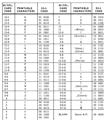
1.2.1. Assembler Character Set
The assembler uses the XS-3 character set as defined in Table 1-1. If alphanumeric data is to be generated in a different code convention, the CHAR directive, described in 2.7, may be used.
80 COL. 80 COL.
CARD PRINTABLE XS-3 CARD PRINTABLE XS-3
CODE CHARACTERS CODE CODE CHARACTERS CODE
12-1 A 01 0100 7 7 00 1010
12-2 B 01 0101 8 8 00 1011
12-3 C 01 0110 9 9 00 1100
12-4 D 01 all 1 12 + 01 0000
12-5 E 01 1000 II -(Minus) 00 0010
12-6 F 01 1001 12-0 ? 01 0011
12-7 G 01 i010 ll-O !(Exclam.) 10 0011
12-8 H 01 lOll a-I / 11 0100
12-9 1 01 1100 2-8 & 11 0011
ll-l J 10 0100 3-8 = 01 1101
ll-2 K 10 0101 4-8 '(Apos.) 10 ll10
11-3 L 10 0110 5-8 :(Colon) 01 0001
11-4 M 10 01ll 6-8
>
II 111011-5 N 10 1000 7 -8 @ 10 0000
11-6 0 10 1001 12-3-8 .(Period) 01 0010
11-7 P 10 1010 12 -4,,8 ) 11 1101
11-8 Q 10 1011 12 -5,8 [ 00 1111
11-9 R 10 11 00 12 -6-8 < 01 ll10
0-2 S 11 0101 12 -7-8 It 01 III 1
0-3 T 11 0110 11-3 -8 $ 10 OOLO
0-4 U 11 0111 11-4-8
*
10 00010-5 V 11 1000 11-5-8
1
00 00010-6 W 11 1001 11-6-8 ;(Sem i-co I) 00 111 a
0-7
x
11 1010 11-7 -8 ~ 10 11110-8 y 11 1011 0-2-8 i 11 0000
0-9 Z 11 11 00 0-3-8 ,(Comma) II 0010
0 a 00 001l 0-4-8 ( II 0001
1 1 00 0100 0-5-8 % 10 1101
2 2 00 0101 0-6-8
"
00 11013 3 00 0110 0-7 -8 ):{ II 1111
4 4 00 0111
5 5 00 1000 BLANK Space N.P. 00 0000
6 6 00 1001
Table 7 -7. Assembler Character Set
1.3. DESCRIPTION OF FIELDS
The programmer is primarily concerned with the label field, operation field, and operand field. The label field must start in column 1. The fields following the label field are freeform and may start in column 2 if there is no label field.
1.3.1. Label Field
The label field is optional. When used, the label field must start in column 1. No other field may start in column 1. The label field may contain a declaration of a specific location counter, a label, or both. The label field is terminated by a blank.
_UR_P_;_~_~9_19
_ _ ..A.o-_ _ _ _ U_N_I_V_A_C_4_1_8_.I_I_I_R_T_O_S_A_S_S_E_M_B_L_E_R _ _ _ _ ...a.-_ _ _ _ _ ---'I...S_E_C_T_IO_N_:_l _ _~l!!,._~_
1.3.1.1. Simple Labels
LABEL
A label identifies a value or a line of symbolic coding. When a label is used, the assembler assigns it a relative address which is the value of the current controlling location counter. A relative address is not assigned to a label used with assembler directives EQU, NAME, FORM, PROC, DO, LIT (see Section 2).
A ~.!l~l consists of one to s-.Lx.Hlphat:Iu.me!i_c characters starting with an alphabetic
chara~t.~!)n~(?!tl~J:Lr --. - - - .. - .... -.~-.-- . 0
~~cial c~ara~~.~rs are nOl ~llowed. within a lab,e!. To ensure uniqueness, many system labels use the $ as part of the label. U sing the $ as part of a label should be avoided to assure this uniqueness of system labels.
Labels defined in the aforementioned manner are referred to as simple labels and are allowed on any statement. If a label is the only nonblank field on a statement, the label is defined as identifying the next location counter value to be generated.
Example:
OPERATION
10 20 30 OPERAND 40
COMMENTS 50
lu~JQJ;J~._L_..LL..L.bb~L
..
L_L ....L.._L.L_L~L.LL_L,..LJ_L...l
,..LL._L-L"., . ...Ll L l L.,L . .J_L.L",.L.-l.,L .. L.1.1 . l 1I
1 1.1ML~$L~.·,L.L
.. L.l.L_J , ... L ... 1 .. .-1 ... ,L ... L ... L ...L ...
L.1 , .. ,J_.J",L".L...L...L,.L.J.,._L."L . ..J "' .. ,.L.L .. , .... L_L., . .1 .. L " . .1. .. L .. L L_L,.L_-1. .. .. 1 J .. 1 LI
I J I j JBl~L.J
.. L.L . .L.l . ..LlbLbL-L ..1_LL~~J~~L-Ll_LL..L.L..L
... LL ... ,.L-L .. "L..l,.U.,_..L.1_L .. L.J.. J .. 1 .... L.L.1 1 .. j1.3.1.2. External Labels
LABEL
An externally defined label is one which may be accessed bL_~tE~~ll1s. The loader will correiate th·e references between the external label re~erence~
In one program and the corresponding external label de-f~itions in another. To define an external lab~~!. an asterisk is appended
.!.()
the label.Example:
OPERATION
10 20 30 OPERAND 40
COMMENTS 50
1 1
LL~1~iJLL.LL_L.Lfu~....L._LLLLLJ5'LL.LL1-L-LJ.
..Ld~~CtA~_1~~~~.L1
.LL .. 1 .. .1 1 ... J 1.1, L .. 1 '--_.Irl~_LiMr
...
L .... L l ..J---.lAL~~L-.LL
.....L.L-..LLJ~J_.J
., .. L .. J ... L ... L. _L ....L.-.L!L~~lIlg1~}f A~\..JYJ.. 1l:lt£Jf:.Ll,~.i
E'i
Ot
lL.IAJ9
le.l~1
J
L .. .! 1 . .1 I I J 1 1 1 I
1.3.1.3. Dimensioned (Subscripted) Labels
UP-7599
Rev. 1 UNIVAC 418-111 RTOS ASSEMBLER 1
SECTION:
The dimensioned label is identified by the format:
The number of subscripts used in defining a dimensioned label is referred to as its dimensionality. The maximum dimensionality of a subscripted label is un-specified. The dimensionality of a subscripted label is constant, that is, once a member of the set is defined, all other explicitly defined members must have the same number of subscripts even though each subscript value may differ.
Example:
LABEL OPERATION OPERAND
10 20 30 40
.~( 13L)I~l_l----LL
__ LJ±15"L 1 ... L ... L .. l .. .l L LJ L - l L_.l . ..L--.1 .L-l L_J _L.L .. -L-.l. L.I .L ... L _ L U . L J ... L . .l J...-l 'l(l'+LILlL)L_LL.J..l±L4fL 1 L .. L I J. L l L.1 L . I 1.. . .1 .. L I L 1 1 "-_.1..1 L.-i 1 .. L .... L_L ... ;. __ L ..• _,.LC.ttLAL{L3ili
J.tlu.)
L.L~..l7L~--.L--.lL.L
__ l L . L , L L .. L_LJ __ J .... -L_L._LJ. L L .--.L .. L--.1. I~
,L_L . ..L.L-.L.L .. .L". LJ. L-l,'D1lle
L(LM1~lLlaLL".L.t.l\
.i)l)l. t l\,J
J_l~L$LL_..LL.1
. L l L.l .L_L ... L_L .. ,..L,.i .. - ' -....l~,.
LL-'--L_L--.l,. L_.lI : I I I I I I I 1
I
1 I I I ! ! I I ! I 1 I I ! I ! I i I ! I ! ! !
Explanation:
• Line 1 defines a one-dimensional label A(3). The subscript value is 3. • Line 2 defines a two-dimensional label B(4,1) with subscript values 4 and 1.
• Line 3 defines a two-dimensional label C(A(3),2) with subscript values A(3) and 2.
• Line 4 defines a two-dimensional label D(C(A(3),B(4,1)),1) with subscript values C(A(3),B(4,1)) and 1.
Dimensioned labels may not be defined to be external to the program assembly.
If used within procedures (see Section 3), the dimensioned labels may be defined as accessible at lower levels by appending the appropriate number of asterisks immediately following the label and before the left parenthesis.
Dimensioned labels may be defined to have a value in magnitude of 236 _1 or less.
If any item used in defining the value of the expression is a double-word item (see 1.4), the la be 1 has a double-word value (see 2.2).
The value of a dimensioned label may be redefined in the course of the assembly without resulting in a 'D-flag'.
If reference is made to an undefined member of a defined set of dimensioned labels, the value of the undefined item is assumed to be a defined zero. If no member of the set is defined, the value is zero and an external reference is made to the label.
4
UP-7S99
Rev. 1 UNIVAC 418-111 RTOS ASSEMBLER SECTION: 1
Example:
000001
70 000 0
000002 U 00 000000
+ 1 .. 12 00
000003 000001
00000" 00 000001 70 0000
+ 6.12 00 ooooos
/ .
L.LK A (1 )
ell) HlU 1
L.LK IH2)
END
•••
SUMMARY•••
PROGRAM SIZE: 00 00002
EXTERNA~ OR UNOEfJNEO REFERENCES: A
Explanation:
• Line 2 references the label A(l). Since no member of the set A(i) is defined, an external reference to A is made.
• Line 3 defines the set B(i) in general and the member B(l) in particular. • Line 4 references an undefined mem ber of the set B(i). Its value is taken to
be zero.
PAGE:
If reference is made to a dimensioned label, some member of which was previously defined with a smaller dimensionality, an expression error results, and the value of the referenced label is ta ken to be zero.
Example:
LABEL OPERATION OPERAND
10 20 30 40
~~~jlJL
_
-1 L~ L_LLEJ~lIL_L__
J __ L L - L L __ L5LJ L i .. L l L 1 1 i l I 1__ .L .... L.-1 1.... __ L i 1 .. 1 1.
Ll..ll..tKt ...
L .. t.. __ .-.J ... .L_L L .. L{\ltJU ..J1J.l
1 L j~ 1 l I 1 L J I 1 IAs stated previously, the dimensionality of a subscripted label is constant. As a result, all members of a set of dimensioned labels must have the same number of subscripts. An expression error results if a subscripted label is defined at a different dimensionality than another member of the same set, that is, with different subscript values but using the same label.
While the user defines the values of a p articular dimensioned label, the assembler internally defines values for the label with lower dimensionalities. These may be referenced (but not defined) in the course of the assembly. For example, if the label A(1,2,3,4) is defined, the labels A, A(l), A(1,2), and A(1,2,3) are internally defined by the assembler. (Note that the name of a dimensioned label must be unique and may not duplicate a simple label.) If a dimensioned label is defined, all labels of lower dimensionality having the sam e nam e are therefore im plici tly defined by the assembler. The values associated with these assembler-defined labels is described in the following paragraphs.
UP-7S99
Rev. 1
1
UNIVAC 418·111 RTOS ASSEMB
LER
SEC TION: PAGE:
An n-dimensional set of labels, A(sl' s2' s3"" ,sn) is defined. Many different values of. each of the subscripts si may have been used in defining the set of labels. Each subscript si has been used ni times; there are ni different subscript values si'
The set of labels defined is: A(1,2,3) A(5,7,3) A(5,8,3) A(7,2,2) A(8,9,O) A(1,2,4)
Then': n1 = 4 because there are four different subscript values defined in the first dimension;
for sl
=
1, n2=
1because only one subscript value (s2 2) has been defined; for s1 = 5, n2 = 2
because two values (s2 = 7 and 8) have been defined with the same subscript s1 = 5;
for s1
=
7 and 8, n2=
1because one value (s2 = 2, s2 = 9), has been defined with each of the subscripts sl = 7 and s1 = 8;
for sl
=
1 and s2=
2, n2=
2because there are two values (s 3 3, s3 = 4) with the same subscripts s1 = 1 and s2 = 2.
The dimensioned labels of the form label(sl,s2, ... ,Sj)' where j
<
n, are defined by the ass em bIer to have values equal to the number of different subscripts used in the next higher dimension specification.Example: 000001 000002 000003 00000'1 000005 000006 000007 000008
000009 00 OUOOOO
000010 00 000001
OOUOSI 00 000002
000012 00 OUOO03
0000 II 00 00000'1
00001'1 00 000005
000015 00 0000U6
000016 0001"'1 000310 000'15'1 000620 00076'+ 001130 0001'1'1 00000'1 000001 000002 000001 000002 000000 / .
~ll,2,3J EQU 100
AIS,7,3J EQU 200
AIS,8,3J EQU 300
AI7,2,2J EQV "00
A(8,9,0. EQU SOD
AII,2,,,. EQU 600
+AII,2,3) +A +A ( 1 )
+A IS)
+.171
+A (1,2) +A(5,9) ENO
UP-7599 Rev. 1
1
UNIVAC 418·111 RTOS ASSEMBLER
SECTION:
Explanation:
• Lines 2 through 7 define a set of dimensioned labels A. • Line 9 generates the value of the label A(1,2,3).
• Line 10 generates a number equal to the number of different subscript values s1 defined in the set. A = 4 because n1 = 4 (sl = 1,5,7,8).
• Line 11 generates a number equal to the number of different subscript values s2 defined in the set A with sl = 1. A(l) = 1 because only s2 = 2 has been defined with sl
=
1.• Line 12 generates the value n2 for s1 = 5. n2 = 2 because s2 = 7 and 8 for sl = 5. • Line 13 generates the value n2 for sl = 7.
n2 = 1 because only s2 = 2 for s1 = 7.
• Line 14 generates the value n3 for sl
=
1 and s2=
2. n3 = 2 because s3 = 3 and 4 fors1 = 1, s2 = 2. • Line 15 generates the value n3 for sl = 5 and s2 = 9.n3
=
0 because no value with s2=
9 has been defined.Label Value Definition
A(1,2,3) 100 explicit*
A(S,7,3) 200 explici t*
A(S,8,3) 300 explicit*
A(7,2,2) 400 explici t*
A(8,9,0) 500 explicit*
A(1,2,4) 600 explicit*
A 4 implicit
A(l) 1 implicit
A(S) 2 implicit
A(7) 1 implici t
A(8) 1 implici t
A(1,2) 2 implicit
A(S,7) 1 implicit
A(S,8) 1 implicit
A(7,2) 1 implicit
A(8,9) 1 implicit
A(9) and all
others 0 implici t
*See foregoing example.
7
UP-7599
Rev. 1 UNIVAC 418-111 RTOS ASSEMBLER SECTION:
1
The purpose of using dimensioned labels as opposed to simple labels may vary. The DO directive and procedures are capable of generating more than one word of data or series of instructions. Combined with these tools, dimensioned labels provide an extremely convenient method for manipulating arrays of any desired dimension.
1.3.1.4. Location Counter Declaration
When a program element is assembled, relocatable object code is produced as a result of the assembly. When the assembled program is loaded by the loader, the actual address values are assigned. The relocatable code produced by the assem-bler is therefore relative to a base address assigned by the loader when the
PAGE:
program is executed. A location counter specifies under which base address a particular word is to be generated. There are 16 location counters (0-15) within anyone assem bly. Any location counter may be used or referenced in any sequence. The loader regroups the data generated under the various location counters so that each appears in memory as though the code within the location counter was gener-ated contiguously.
A program remains under control of location counter 0 if no location counter is explicitly specified. When a specific location counter is specified, all subsequent coding is generated under its control until another location counter is specified.
->
A specific location counter may be activated by $(n) as the first entry in thelabel field, where n represents an expression whose value is within the range of 0 through 15 and denotes the location counter to be activated.
Coding may be present in the same statement which defines a new location counter. If this is done, the code generated will be under control of the new location counter. If a label is desired on a line of code which also defines a new location counter, the format is:
$(n),label operation operand
If a symbol is used in defining the location counter, it must have been previously defined.
Example:
000001 / .
000002 00 OOoouo 70 00050 LL.K S
000003 00 000001 SS 0003 Jl (LABEL.)
00000'+ 05 000000 71 0003 S(S),L.ABEL. _L.t( 3
000005 L.IT
000006 as OUOO01 50S 0002 JI (5(0) I
000007 Sll-ll,
000008 00 000002 770301 ERRORs
000009 END
00 OUOO03 000000 05 0 0 0002 000002
UP-7S99
Rev. 1
1
UNIVAC 418·111 RTOS ASSEMBLER
SECTION:
Explanation:
• Line 2 generates an LLK 5 instruction under location counter O.
• Line 3 transfers control to the address denoted by LABEL, which is not necessarily the next address because it is defined under a different location counter.
• Line 4 defines LABEL under location counter 5 and generates an ALK 3 in-struction under location counter 5.
• Line 6 transfers control back to the next address under location counter O. • Line 7 reactivates location counter O.
• Line 8 generates a procedure call ERROR$. The transfer made in line 6 will be to this addr€ss.
1.3.2. Operation Field
The operation field defines the purpose of the symbolic statement. The operation field starts with the first nonblank character following the label field. If no label field value is present, at least one blank character must be coded before defining the operation field. The operation field may contain anyone of the following: • a mnemonic operation code identifying which instruction is to be generated; • an assembler directive specifying some special function to be performed by the
assem bIer (see Section 2);
• a FORM reference specifying that a data word is to be constructed according to the format defined by the FORM directive (see Section 2);
• a procedure reference specifying that some procedure is to be assembled (see Section 3); or
• a data word generating code specifying that one or more words of data constants are to be generated.
The operation field must be terminated by at least one blank character unless: • a procedure reference is made,
• a data generating code is defined, or
• a period is used to terminate the entire statement.
If a procedure reference is made, the operation field may be terminated by a comma followed by procedure parameters. If a data generation code is defined, the data word may immediately follow the identifier.
The content of the operation field determines the value of the active location counter. If an instruction is generated, the location counter is incremented by 1 or 2 depending on whether an 18- or 36-bi t instruction is to be generated, If an assembler directive is referenced, the location counter value mayor may not be advanced depending on the specific directive, A FORM reference may cause the location counter to be advanced by one or two depending on the specified FORM directive. A procedure reference may cause the location counter to be advanced by an indefinite value, depending entirely on the definition of the procedure sample.
9
UP-7599
Rev. 1 UNIVAC 418~11I RTOS ASSEMBLER SECTION:
1 10
PAGE:
----~---~---~---
...
A data word generating code will cause the location counter to be advanced depending on the number of words generated.
Example:
000001 / .
000002 00 000000 36 0003 LBK 3
00000) F'R FORM 6,U
00000" 00 000001 00 0002 F'R o,LABEL
000005 U flRCAL.,PARI
000006 00 OOOOU2 20'4511 LABEL +10.3
00 0 0 0003 '1631'46
000007 END
Explanation:
• Line 2 specifies generation of an LBK instruction. • Line 3 is an assembler directive defining the format FR. • Line 4 is a FORM reference.
• Line 5 is a procedure reference on the procedure PRCALL. • Line 6 is a data constant.
1.3.3. Operand Field
The operand field starts with the first nonblank character following the operation field. The components of the operand field are called expressions or subfields and define the information necessary to complete the type of statement specified by the operation field.
The operand of a mnemonic instruction or data constant requires only one expression which is terminated by a blank character.
Several of the assembler directi ves do not require an operand. Others require several expressions. When groups of expressions are used, they are separated by commas. A group of such expressions is referred to as a list of expressions. Procedures may permit multiple lists of expressions. When omitting a subfield other than the first or last subfield, the construction comma-zero-comma (,0,) or two contiguous commas (,,) is necessary. Ending subfields may be om itted entirely if unnecessary.
Example:
LABEL OPERATION OPERAND
10 20 30 40
i . 1 . .1. .... 1.. . ..1 L.1. ..L_..L j ... ~~.1KJ . L l L . L ... LLJS 1 . I I L L L . L I .1 L L.L ... L 1 L I .1 ... L .... LL ... L .L.t .... L._L ... .L..J L .... ' 1. .. l .. L L.J L .LJS1~..L I .L I . .l. 1 1 J ITl~&l I J .. 1 .J .. J . .1. 1._1 .... L.L ... 1..J L.L .... L .. I . L . L . .... L L _ L . .L....!i . . i ... J. j .L L J
L.L.L..~~E.L..L L_L ....
L.l. .1110.1 1.L.JfA('I~
..
l'il&.J~L~JLO'LJ.TliL~~~.Li
.L.1 ..._L.J ... L ... 1 ... .1. . I . .1 ..
J I I I i i I i i ' I I I I I
UP-7S99
Rev. 1 SECTION:
1
UNIVAC 418-111 RTOS ASSEMBLER
Explanation:
• Line 1 is a mnemonic instruction. The operand field contains an expression whose value is 5.
• Line 2 is a mnemonic instruction. The operand field contains an expression whose value is the relocatable address TAG.
• Line 3 is a procedure call containing five lists of expressions. • Line 4 is a mnemonic instruction not requiring an operand.
• Line 5 is a FORM directive. The operand field contains one list of three expressions or subfields.
PAGE:
1.3.4. Comment Field
The construction space-period-space (15.15) terminates a line of coding. Any addi-tional subfields implied by the operation field are taken to be zero. Any characters following the space-period-space are printed on the assembly listing and may be used as comments to clarify the purpose of the line of code. If the operand field has been totally specified, comments may immediately follow the blank character which terminates- the operand field.
1.3.5. Line Continuation
000001 000002 000001 00000" 000005 000006 000007 000008 000009 000010 000011 1.3.6.
A sym bolic line may be continued to the next card image. When a semicolon is encountered during the processing of the label field, the operation field, or the operand field, the next card image is read and processing continues starting with the next nonblank character. If a new list is to be defined on a continuation card, at least one space should occur before the semicolon.
If a semicolon occurs in the comment field, whether defined or implied, it is not treated as a continuation character, and the next card image is processed separately. Continuation to the next card may be specified in any of the three basic fields. In some situations, such as the first reference to a library procedure, the label and operation field must be specified on the same card image. In general, it is recom-mended that semicolons only be used in the operand field.
Example:
00 0 0 0000 000000 00 0 0 0001
000002 000003
D 777776
D 000000
Ejection of Paper
/ . LABEL LABELT A e TAG TAG .5 RES EQU E!ilU EQU EQU END 10 2 3 LABEL+l-CA>0)-CS<5J
LABI COMMENTS MAY
ELT. FOLLOW THE I
+l .. U>O,-; CB<iJ
A slash (/) appearing in column 1 advances paper in the printer to the top of the next page. This line may not contain any coding but may contain comments. The slash prints on the new page (see 2.11).
UP-7S99
Rev. 1 UNIVAC 418-111 RTOS ASSEMBLER
I
SECTION, 11.4. EXPRESSIONS
An expression is an elementary item or a series of elementary items connected by operators. Blanks are not permitted within expressions. The values of elementary items can be combined through operators (see 1.4 .2). The res ulting value becomes the value of the expression. In addition to having an arithmetic value, each elemen-tary item has associated with it a mode value which indicates whether the numeric value of the item is constant, that is, cannot be changed, or is relocatable, that is, relative to some base constant to be determined at some later time. This base con-stant is generally a storage address or drum address determined by the job loader prior to execution of the program. In combining elementary items to form an expression, the mode values of the items are also operated upon to form the mode value of the expression. When combining elementary items to form an expression, some care must be exercised to ensure that the resulting mode value of the expression is also correct (see 1.4.4).
In combining elementary items to form an expression, the symbolic statement is scanned and interpreted from left to right. Parentheses may be used to force items to be combined in a different order. All expressions within parentheses are evaluated before their results are available to be operated upon. Up to six nested levels of parentheses may be used.
1.4.1. Elementary Items
An elementary item is the smallest element of assembler code that can stand alone; an elementary item does not contain an operator.
The magnitude of the value of an elementary item may not exceed 236 _1, that is, 0777777777777. If an elem entary item is not defined, it is assigned a value of zero. Expressions containing undefined (externally referenced) elementary items may not exceed a magnitude of 218 _1, that is, 0777777.
There are eight ways in which elementary item s may be represented. They are discussed in the following paragraphs.
1.4.1.1. Symbolic Label
Any label may be used as an elementary item. The value of the item is the relocatable location counter value of the statement associated with the label.
If the label was defined with an EQU directive, the item value is that of the operand expression of the EQU statement. Undefined labels have a constant zero value.
Example:
000001 000002 000003 00000"
Explanation:
00 oUoooo
DO 000001
12 000 I 12 0000
/ .
TAG2
TAG
LI. I.\,
ENo
TAG TAG2
PAGE:
• Line 2 defines TAG2 to have a value equal to the relocatable location counter value of the word containing the instruction LL TAG. The operand field contains an expression formed by a single elementary item TAG. The value of TAG is defined in line 3 as the relocatable location counter value of the word contain-ing the instruction LL TAG2.
UP-7599
Rev. 1 UNIVAC 418·111 RTOS ASSEMBLER SECTION: 1
1.4.1.2. Location Counter
The relocatable value of any of the location counters may be used as an elemen-tary item. The symbolic representation of a location counter value reference has the form:
$(expression) or $
If a dollar sign alone is used, the value of the elementary item is the current value of the active location counter. If a dollar sign followed by a left paren-thesis is used, the expression value contained within the parenparen-thesis defines which location counter is referenced. The value of the expression must be between 0 and 15. It should be remembered in using the $+n that some instruc-tions increment the location counter value by 2.
Example: 000001 000002 000003 00000'1 000005 000006 000007
1.4.1.3. Octal Numbers
00 000000 02 DUO 000 00 0 0 0010 00 0 0 0011 00 000012 00 000013
000010 S5 0001 3'1 001'1 S02000 000001
/ . s (21
s (0)
RES + JI J LSD END 8 $(0) 5(2. '+3 SUI
An octal number is an elementary item. An octal number consists of a group of octal integers (0-7) preceded by a O. The value of the number is the value of the elementary item.
Example: 000001 000002 000003 00000'1 000005
00 000000 00 000001 00 000002 00 000003
000077 000301 013013 36 001 7
1.4.1.3.1. Double-Precision Octal Num bers
/ .
+077 +0301013013
LBK 017
END
A double-precision octal value is produced by writing an octal constant larger than 18 bits or placing a letter D immediately after the last octal digit.
Example:
00000& / .
000002 00 0 0 0000 000000 +0770
00 000001 000077
OooOOl 00 000002 000001 +01000000
00 000003 000000
00000'1 00 oOooo"! 000000 +10+ 0 17
00 OOooos 000020
ooooos END
13
UP-7599
Rev. 1
UN I V A
C 418·111
R TO S AS S E MB L E R 1SEC TION:
1.4.1.4. Decimal Numbers
A decimal number is an elementary item. A decimal number consists of a group of decimal integers (0-9) the first of which is not a zero., The value of the elementary item is the value of the num ber.
Example: 000001 000002 000003 00000'1 oooa05
00 oUoooo 00 OUOOUI 00 OOOOOl
00011 S 000100 36 0017
I . +77 +6~ LBK END 15
1.4.1.4.1. Double-Precision Decimal Numbers
1.4.1. 5.
A double-precision decimal value is produced by writing a decimal constant whose value is larger than 0777777 or by placing a letter D immediately after the last decimal digit.
Example:
000001 I.
000002 00 OUOOOO 000000 +770
00 OUOOUI 00011S
oOOOOl 00 000002 000000 +6'1D
00 0 0 0003 000100
00000'1 00 00000'1 000000 +10+17
00 OOooos 000022
000005 END
Alpha Constants
Alphabetic, num eric, and special characters may be represented in 6-bit XS-3 code. When such characters are enclosed within apostrophes, the enclosed characters together form an alpha constant. The value associated with each character of the alpha constant is the 6-bit XS-3 code as defined in Table 1-1.
The value of the elementary item is formed by stringing together the values associated with each character.
NO TE: A semicolon is a special character which is generated when enclosed
PAGE:
by apostrophes. Therefore, it may not be used as a continuation character in an alpha constant or alpha string.
Example: 000001 000002 000003 00000'1 000005 000006 000001
00 000000 00 000001 00 OOOOOl 00 000003 00 DUO 00 'I
00002'1 002'125 2'12526 70 0021f 71 0001
UP-7599
Rev. 1 UNIVAC 418-111 RTOS ASSEMBLER
1
5 EC TION:
The 6-bit value associated with a character in an alpha constant may be re-defined through the use of the CHAR assembler directive (see 2.7).
An apostrophe may be present as a character within the alpha constant by coding two contiguous apostrophes for each apostrophe in the constant. Example:
000001 000002 000003 00000"
00 OUOOOD 00 OUOOOl
000056 56562 ..
/ .
+' , , ,
. ' " "II' END
If the alpha constant consists of one, two, or three characters, the value of the elem entary item is right-j ustified, zerofilled. If the alpha cons tant consists of four, five, or six characters, the value of the elementary item is left-justified, spacefilled, and generates two words.
An alpha constant may not consist of more than six characters (see 1.5.2).
Example:
000001 I .
000002 00 OUoooo 00002 .. +'A'
000003 00 000001 002 .. 25 +'118'
00000" 00 000002 2 .. 2526 +'ABC'
000005 00 000003 2 .. 2526 +'IIBCO'
00 00000'1 270000
000006 00 oOooos 2 .. 2526 +'IIBC
,
00 000006 000000
000U07 END
1.4.1.5.1. Double-Precision Alpha Constants
A double-precision alpha constant is one which consists of four, five, or six characters, or one which is immediately followed by the letter D.
Example:
000001 / .
000002 00 000000 000000 .'II'D
00 0 0 0001 00002 ..
000003 00 000002 2142526 +'1I8C DE'
00 OUOO03 002730
00000" END
15
UP-7S99
Rev. 1 UNIVAC 418·111 RTOS ASSEMBLER SECTION: 1
1.4.1.6. Floating-Point Numbers
1.4.1.7.
A floating-point number is an elementary item. The value of the elementary item is the 36-bit binary number formatted according to the hardware representation of floating-point numbers. Note that in manipulating floating-point elementary items, the assem bIer uses double-precision in teg er arithm etic so that expressions of the type
1.0 + 1
result in a binary number which is the result of an integer arithmetic addition of the two elementary items.
A floating-point number is recognized by the presence of a decimal point immedi-ately following a decimal number. The format of a floating point number is one of the following:
d.
d.d d.dEse d.Ese d.Ee
where: d represents one or more decimal digits.
s represents the sign of the characteristic and may be either + or -. e represents one or more decimal digits which define the power of 10
by which the number is to be multiplied.
Example:
00000& I.
000002 00 000000 20&'100 +1.
00 000001 000000
OOOOOl 00 0000U2 201'103 +, .015
00 000003 656050
00000'1 00 00000'1 200'100 +0.5
00 000005 000000
0000 as 00 000006 203S00 +0.5E+l
00 000007 000000
000006 00 000010 17'1631 +0.5E"'&
00 OUOOll '1631'16
000007 00 000012 216'171 +100.32'1E2
00 000013 '10631'1
000008 END
Parameter Reference Form
The parameter reference form (PARAFORM) is an elementary item as long as the procedure sample is being processed. The definition, explanation, and use of paraform s are given in Section 3.
16
UP-7S99
Rev. 1 UNIVAC 418-111 RTOS ASSEMBLER SECTION: 1 PAGE:
1.4.1.8. Line Item s (Literals)
1.4.2.
A line item is any symbolic line, less label, enclosed in parentheses. Line items may be elementary items.
A literal is represented as an expression enclosed within parentheses and without connecting operators. The assembler then generates a word containing the expres-sion value, and this word appears in a literal table at the end of the program. The value of the line item is the address of the generated constant.
Duplicate literals do not appear in the literal list. When location counters are used, the literals appear at the end of the coding associated with a particular counter with only duplicated literals for that particular counter eliminated (see
2.16).
Literals may be double-precision if the symbolic line is a single subfield data of the double-precision form. The value of this expression is the address of the first word of the literal.
Line items within line items are permitted up to five levels. If an operator im-mediately precedes an item enclosed within parentheses, the item is not a literal. Example:
000001
/-000002 00 000000 12 0007 LL (fENDt)
000003 00 OOOOUI 32 DOlO LB (0101)
00000'1 00 OOOOU2 10 00 II LU (J 5+5)
000005 00 000003 10 001 3 LU (L.U (01711
000006 00 OUOOO'l 70 '+600 L.LI( +(SLL 0)
000007 00 00000& 10 001'+ LA (1. a I
00 OOOOOh 12 0015
000008 END
00 000007 305027 00 0 0 0010 000101 00 0 0 0011 311 0007 00 000012 000017 00 OUOO13 10 001 2 00 OllOOI11 2011100 00 000015 000000
Operators
There are 12 operators in the assembler which designate the method, and implicitly the sequence, to be employed in combining elementary items within a subfield. Blanks are not permitted within an expression. Evaluation of an expression begins with the substitution of values for each elementary item. The operations are then performed from left to right in hierarchical order as listed in Table 1-2. All the operators listed are assembly-tim e operators.
The operation with the highest hierarchy number is performed first; operations with the same hierarchy number are performed from left to right. To alter this order, parentheses may be employed but care should be taken to avoid redundant paren-theses which may result in the generation of a literal.
UP-7S99
Rev. 1 UNIVAC 418-111 RTOS ASSEMBLER SECTION: 1
If an elementary item or an expression is enclosed in parentheses and an operator appears adjacent to the parentheses, the function of the parentheses is that of algebraic grouping. The value of this quantity is the algebraic solution of the items or expression enclosed in parentheses. This value should not be confused with the value produced by a literal and, therefore, is not an address.
HI ERARCHY OPERATOR DESCRIPTION
H ighest6 *1 a*/b is equivalent to a*2b
5 * arithmetic product
I arithmetic quotient
/1 covered quotient (allb is equivalent to
a + : - l )
4 + arithmetic sum
-
arithmetic difference3 ** logical product (AND)
;
1 10o
002 ++ I ogi cal sum (0 R)
~
1 11o
102
--
logical difference(EXCLUSIVE OR)
~
1 01o
10 Lowest 1=
a=
b has the value of 1 if true,o
if otherwise> a> b has the value of 1 if true,
o
if otherwi se«
a<
b has the value of 1 if true,o
if otherw iseT obI e 7 - 2. Hierarchy 0 f Operato rs
PAGE:
In the absence of parentheses, the rules of priority determine the sequence in which operations are performed within an expression. When two or more operators of the same priority are used, the sequence of interpretation is from left to right. The following two sample problems illustrate this point:
PROBLEM 1: 9-2*3++12**6 The result is
7.
after step 1 9-6++12**6 after step 2 3++12**6 after step 3 3++4
after step 4
7
UP-7S99
Rev. 1 UNIVAC 418-111 RTOS ASSEMBLER
PROBLEM 2: after step 1 after step 2 after step 3 after step 4
1.4.2.1. Shift Exponent (*/)
((9-(2*3/4»++12)**6
((9-1)++12)**6 (8++12)**6 12**6 4
1
SECTION:
The result is 4.
The shift exponent allows the programmer to enter a number and specify its binary positioning to the assembler. The shift may be left or right according to the sign of the exponent (-b produces a right shift). x*
Ib
is equivalent to x*2 b .If the sign of the exponent is positive, a left-circular shift of the number is performed. If the sign of the exponent is negative, a right-arithmetic shift of the number is performed.
Example:
00000& 000002 000003 00000" 000005 000006
00 000000 00 000001 00 0000lJ2 00 0 0 0003
1.4.2.2. Arithmetic Product (*)
000060 000003 777770 700000
+6./3 ,_6.8
+6./-1 ._6/2
-073./-3 ,-.073/8
+10777777./18)./-3
ENo
The integer value of the first item, the multiplicand, is multiplied by the integer value of the second item, the multiplier, to produce a product which becomes the value of the expression or next item.
Example:
000001 / ,
000002 00 0(,)0000 000020 +'1."
00 000001 0000'+0 .".1·/3 ... a
000003
.1 .. ·.£)·/3 ._a.a
00000" 00 0(,)0002 000100
5
000005 OOOOOS 1 L EQU
~F EQu 2
000006 000002
000007 000012 BL EQU JL·SF
000008 END
19
UP-7S99
Rev. 1 UNIVAC 418-111 RTOS ASSEMBLER SECTION: 1
1.4.2.3. Arithmetic Quotient (/)
The integer value of the first item, the dividend, is divided by the integer value of the second element, the divisor, and the resultant quotient becomes the value of the expression or next item.
Example: 000001 000002 000003 00000" 000005 000006
00 0 0 0000 00 000001 00 000002 00 000003
000002 000002 000000 000000
/ .
+ .. /2
+ .. _2/3 +,,,(2/3)
+ .. _2/3-/3
END
Note that the remainder of the division is discarded and that the quotient resulting from a divide must be less than 218_1.
1.4.2.4. Covered Quotient (/ /)
The covered quotient operates the same way as the arithmetic quotient with the following exception. If the remainder of the division is greater than zero, one is added to the integer value of the quotient. The resulting integer is substituted in the expression. The covered quotient may be expressed in the following form-ula: a//b Example: 000001 000002 000003 00000 .. ooooos
a + b - 1
b
1.4.2.5. Arithmetic Sum (+)
00 ouoooo 00 OOOOUI 00 0000(12
000002 00000'+ 00000'+ / . +5//3 +2-5//3 +2-(5/13) END
The arithmetic sum operator produces the algebraic integer sum of the values of two items.
Example: 000001 000002 000003 00000" OOOOOS 000006 000007
00 0 0 0000 00 000001 00 000002 00 000003 00 00000'1
000007 12 000 3 000065 000250 000250
/ .
+5+2 LL 1+2 +5+2- 3 -/3 +(5+21-3_/3 +((5+21-31_/3
END
20
UP-7599
Rev. 1 UNIVAC 418-111 RTOS ASSEMBLER
SECTION:
1.4.2.6. Arithmetic Difference (-)
The arithmetic difference operator produces the algebraic integer difference between the values of two items.
Example:
COUOOl
000002 000003 00000'1 OOOOO!) 000006
00 aOoooo 00 OUOOU1 00 OU0002 00 OU0003
1.4.2.7. Logical Product (**)
12 000 2 000003 777776 0000 II
/ .
LL 5+'1-2 +5"2 +5"2-3 +(5 .. 21-3
ENO
1
The logical product operator (AND) produces the logical product of the values of two items.
Example:
03**05 The result is Ol.
000011 ** 000101 000001
1.4.2.8. Logical Sum (++)
The logical sum operator (OR) produces the logical sum of two items.
Example:
03++05 The result is 07. 000011
++ 000101 000111
1.4.2.9. Logical Difference (--)
The logical difference operator (XOR) produces the logical difference between the values of two items.
Example:
03--05 000011 000101 000110
The result is 06.
21
UP-7S99
Rev. 1
~
________ U_N_I_V_A_C __
4_18_ .. II
__
I_R_T_O_S_.A
__
SS_E_M_B_._L_E_R ______
~
___________
~I~s_E_c_T(_O_N:
__
l __
~~PA_G_E_:_2_2
__ ___
1.4.2.10. Equal (=)
The integer value of the first item is compared with the integer value of the second item. If the two values are equal, the result of the operation is a binary 1. If they are not equal, the result of the operation is a binary O.
Example:
OOUOOI 000002 00U003 0000041
00 000 DUD
1.4.2.11. Greater Than (»
ooooos
70 0003
I .
A EQu
LLK END
S
(1.-5)_3+1,,-6)_2
The integer value of the first item is compared with the integer value of the second item. If the value of the first item is greater than the value of the second, the result of the operation is a binary 1. If the integer value of the first item is less than or equal to the second, the result of the operation is a binary O. Example: 000001 000002 00U003 0000041 000005 000006
1.4.2.12. Less Than
«)
00 DUO 00 a 00 OUOOU\ 00 OU0002
0000 Os 36 UOO O 70 000 0 7\ 000 3
I .
A EQu
LBI( I.LK ALK END S 1,,>S'_3+IA<5)_2 (1.>151).3 (1.>2).3
The integer value of the first item is compared with the integer value of the second item. If the value of the first item is less than the value of the second item, the result of the operation is a binary 1. If the first value is greater than or equal to the value of the second, the result of the operation is a binary O. Example: 000001 000002 000003 0000041 000005 000006
00 0 0 0000 00 OUoOU\ 00 OU0002
0000 os
36 0000 70 0003 71 0000
I.
A EQlJ
UP-7S99
Rev. 1
UN I V A C 418 -III R TO 5 A 55 E MB L E R
1SEC TION:
1.4.3. Interbay Offset Operator (!)
The interbay offset operator (lBOO) is a special operator recognized by the assem-bler which operates only on the mode of an expression. When the IBOO operator is present in an expression, a flag is set in the relocation output which causes the loader to relocate the data word in a special manner. If used, the IBOO operator must follow an elementary item, and may be followed by an operator.
Example:
000001 I .
000002 00 000000 32 W00 3 LB CLA~ELf)
00U003 00 OUOOU! 32 000" LEI (LABE.Lf+l)
OOUOU" 00 OUOOU2 000000 LABEL +0
oouoos END
00 OUOO03 000002 00 oUoou,+ 000003
The purpose of the IBOO operator IS to facilitate the accessing of storage in different bays.
Consider the following ways of accessing the contents of location FROM, which may be located anywhere in storage.
Examples:
OOOUOI
000uu2 00 OUOO!.lU 12 OUI2
000003 00 QUoau! 52 001 3
OOUOO'l 00 OUOOU2
"
..
001 0/ .
1.1. (S,
AND (077UUOO)
SI. SAY
000005
00U006 U 00 OOOQU3 12 DOl'!
000007 00 ouoau'! 16 0010
DouDna 00 OUOOU5
....
00 I II.L (FROM)
ANI. BAY
51. FROMR
00U009
I.B FROMR
PAGE:
OOUOIO 00 OUOO06 32 00 II
OOUOll 00 OUOOtJ7 13 OOOD LL eO .CAI,.I-CFROMI
000012 00 OUOOIQ
000U13 00 oUoo 11
00001'1
OC OUOOl2 00 OUOO13 U 00 OUOOI'! OUUOOI
OUU002 U 00 OUOOUU
000003 00 OUOOUI
00000" 00 000002
000005 00 OUOOU.)
00u006
U 00 QUOOO4f
000001
000002 u 00 QOoau()
000003 U 00 OUOOU1
00000" 00 OUOUU2
000005 000000 000000 000000 770000 000000
32 000"
5073 20 13 0000
sn73 00 000000
S073 20
12 0000
5073 00
BAY +0
FROMR +0
END / . Lt.i LSR LL LSR ENO / . LSR LL LSR END (FROM) 020 eO
a .(AL,-(FROHI
020+FROM fROM
o .CAL'-(FROM)
UP-7599
Rev. 1
1.4.4.
UNIVAC 418·111 RTOS ASSEMBLER 1
5 EC TION:
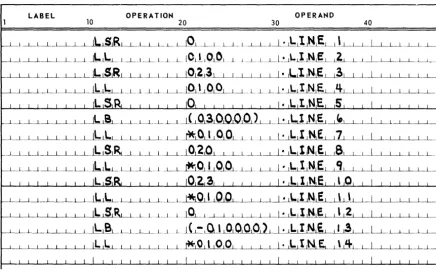
Each of the three foregoing methods has particular advantages. The first example uses six instructions to set up a bay-relative address. Subsequent references use two instructions. The disadvantage comes about if many different locations are to be accessed in this manner.
The second example is disadvantageous if frequent accesses have to be made because four instructions are used each time.
The third example still uses three instructions each time and is valid only if
FROM is an external reference. If FROM is defined within the assembled program, the LSR operand specification should be coded as:
LSR 020 + FROM - (FROM**0777777).
The IBOO operator causes the loader to relocate the specified value as follows: (VALUE)+(REL. BASE)-(BA Y IN WHICH VALUE IS STORED) .
As a result, the above access may be performed as follows:
OOUOOl / .
00UG02 U 00 OUOOOO 32 0002 LB (FROM;
000003 00 OUOOOI 13 0000 LL -0
001.100'1 END
U 00 OUOO02 0000[1" Expression Modes
As stated previously, each elementary item has both an arithmetic and a mode value. When operators are used to combine elementary items to form an expression, the mode values of the elementary items are combined also to form the mode of the expression.
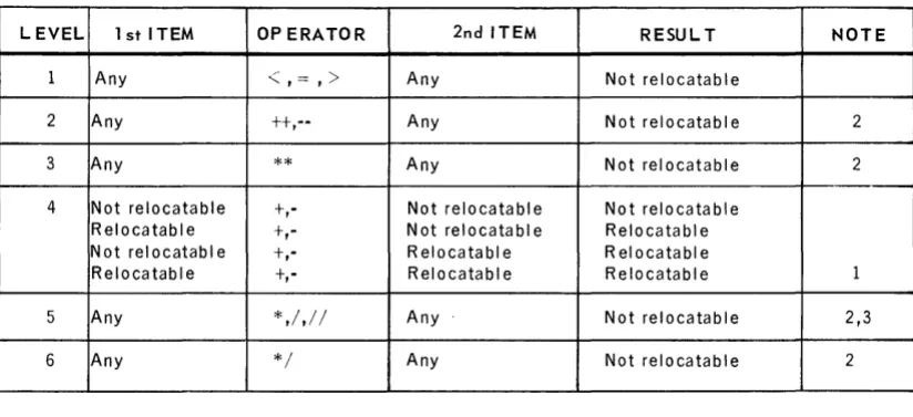
Table 1-3 gives the rules for determining whether the result of a binary operation is relocatable.
24
UP·7599
Rev. 1 UNIVAC 418-111 RTOS ASSEMBLER SECTION: 1
LEVEL 1 st ITEM OP ERATOR 2nd ITEM RESUL T NOTE
1
2 3
4
5
6
Any
<,==,>
Any Not relocatableAny tt,-- Any Not relocatable 2
Any ** Any Not relocatable 2
Not relocatable t,- Not relocatabl e Not relocatable Relocatable t,- Not relocatable Relocatable Not relocatable t,- R elocatabl e Rei ocatabl e
Relocatable t,- Rei ocatabl e Relo c a ta b I e 1
Any *,/,/ / Any Not relocatable 2,3
Any */ Any Not relocatable 2
NOTES:
1. The difference between two relocatable quantities under the same location counter is not relocatable.
2. Except as noted for level 4, the relocation error flag (R) is set for these operations. 3. Multiplication of a relocatable quantity by an absolute 1, or absolute 1 by a relocatable
quantity is relocatable. Multiplication by absolute 0 is absolute O. In either case, no error flag is set.
Table 7 -3. Rules for Determining whether Results of Binary Operations are
Relocatable
The mode values associated with a line of code may be examined by using the M option on the ASM control card (see Section 4).
1.5. DATA WORD GENERA TION
A t or - in the operation field followed by a single subfield generates one or more data words. The t or - sign may be separated from the subfield by any num ber of blanks. If the first item in the expression is anum ber or an alpha constant, the + or - may be omitted. If the mode value of the operand expression signifies that the data word is double-precision, two I8-bit words are generated. In the absence of a
+ sign, the value of a number is taken to be positive.
The operand field of a data generation statement may contain: • an expression or elementary item
• an alpha string
• a double-precis ion floating-point num ber
25
UP-7599
Rev. 1 UNIVAC 418·111 RTOS ASSEMBLER 1
SECTION: PAGE:
1.5.1. Data Word Expressions
1.5.2.
The operand field or operation field may contain an expression. A data word con-sisting of the value of the expression is generated.
Example:
000001 / .
000002 00 000000 000005 +5
00U003 00 OOOOUI 000002 TAG +1+1
00000'1 00 OUOO02 00000'1 +TAG+3
000005 00 000003 201'100 .1.0
00 OOOOU'I 000000
000006 00 00000:' 000000 +50
00 0000U6 OOOOOS
000007 00 0000U7 000001 + (TAG)
000008 00 000010 000012 (T AG I
000009 00 0000 II 001137 +20-(27+2,++037
000010 END
00 000012 OOOOUI
Alpha Strings
An alpha string consists of a series of alphabetic, numeric, and special characters enclosed within apostrophes. Two successive apostrophes within the string are equivalent to a single apostrophe which does not signify the end of the string. For each three characters in the string, one 18-bit data word is generated which consis ts of an alpha constant equal to the binary equivalent of the three characters.
Characters are left-justified, spacefilled unless the string consists of less than three characters. In this case, an alpha constant (right-justified, zerofilled) is generated.
Example:
000001
00U002 000003
00 00 00 00 00 00 00 00 00
0 0 0000 OUOOUI 0 0 0002 OOOOU3 OUOOO'l OUOO05 0000U6 000007 OUOO10
6633J'1 65003'1 65002'1 50002'1 '165233 2'100'5 665'13'1 £103200 00002'1
+'THIS IS AN ALPHA STRING'
·'A'
END
UP-7599
Rev. 1 UNIVAC 418·111 RTOS ASSEMBLER SECTION: 1 PAGE:
1.5.3. Double-Precision Floating-Point Numbers
1.6.
Double-precision floating-point numbers may be generated which conform in format to the conventions established in the FORTRAN compiler. A double-precision floating-point number consists of three 18-bit words. The first word contains the character-istic; the second and third contain the mantissa. If a floating-point elementary item occurs which specifies more than 27 bits of significance, or which contains the letter D in the exponent instead of the letter E, a double-precision floating-point format is generated.
Example:
000001
+1.02
00uD02 00 oUOOOO 0'10007
00 OUOOOI 310000 00 OUOO02 000000
000003 00 000003 0'10001 +1.23'1 •• 789
00 ouooo .. 23601'1 00 000005 S10210
00000'1 00 0000U6 037755 -0.120-5
00 000007 5367'10 00 0 0 0010 501 .. 37
000005 END
DOUBLE-PRECISION EXPRESSIONS
As previously stated, several elementary items may be specified to be double-precision.
If an expression contains a precision item, the expression is said to be a double-precision expression. When a double-double-precision expression is used to generate data, two words are generated, If the line item specified in a literal is a double-precision item, the literal value is the address of the first of the two words generated in the literal table. The following restrictions exist when generating double-precision data words.
• An expression which contains an external reference may not be defined as a double-precision expression.
• Simple labels may be defined to have a value which exceeds 218 _1, but if such labels are used to generate a data constant, only one word is gene'rated which consists of the least significant 18 bits of the value of the label.
Example:
000001 I .
00UOU2 000000 A EQu 01000000
00U003 00 DUO 00 a 000000 +A
00000'1
ooooos 000000 O( 1) EIiIU A
00U006 00 OUOOU1 000000 +0 (11
00U007 00 OUOO02 10 0010 LA ('ABCOE")
00 000003 12 0011
000008 00 OUOOO'l 10 0012 TAG L.A 11.0)
00 OOOOOS 12 001 3
000009 00 0 0 0006 10 001'1 LA (RS TAeal
00 0000U7 12 001 5
00U010 END
00 OUOO10 2'12S20 00 0 0 0011 273031 00 000012 201'100 00 000013 000000 00 00001'1 5010 00 00 000015 00 000'1
UP-7599
Rev. 1
UNIVAC 418-111 RTOS ASSEMBLER
SECTION: 2PAGE:
2. ASSEMBLER DIRECTIVES
2.1. GENERAL
The assembler provides a series of special directives which provide the means to control or direct the generation of obj ect code. The symbolic assembler directives control or direct the assem bly processor just as the hardware operation codes control or direct the central processor. The assembler directives are represented by mnemonics written in the operation field of a symbolic line of code. The directives are used to equate the expressions, control the location counter, format the object code, and control the generation of object code. The general format for the directives is:
label directi ve specification
The manner in which the assembler interprets each directive varies and is describ