Volume 2007, Article ID 23912,14pages doi:10.1155/2007/23912
Research Article
3D Model Search and Retrieval Using the Spherical
Trace Transform
Dimitrios Zarpalas,1, 2Petros Daras,1, 2Apostolos Axenopoulos,1, 2
Dimitrios Tzovaras,1, 2and Michael G. Strintzis1, 2
1Information Processing Laboratory, Electrical and Computer Engineering Department, Aristotle University of Thessaloniki,
Thessaloniki 54006, Greece
2Informatics and Telematics Institute, 1st km Thermi-Panorama Road, P.O.Box 361, Thermi-Thessaloniki 57001, Greece
Received 31 January 2006; Accepted 22 June 2006
Recommended by Ming Ouhyoung
This paper presents a novel methodology for content-based search and retrieval of 3D objects. After proper positioning of the 3D objects using translation and scaling, a set of functionals is applied to the 3D model producing a new domain of concentric spheres. In this new domain, a new set of functionals is applied, resulting in a descriptor vector which is completely rotation invariant and thus suitable for 3D model matching. Further, weights are assigned to each descriptor, so as to significantly improve the retrieval results. Experiments on two different databases of 3D objects are performed so as to evaluate the proposed method in comparison with those most commonly cited in the literature. The experimental results show that the proposed method is superior in terms of precision versus recall and can be used for 3D model search and retrieval in a highly efficient manner.
Copyright © 2007 Dimitrios Zarpalas et al. This is an open access article distributed under the Creative Commons Attribution License, which permits unrestricted use, distribution, and reproduction in any medium, provided the original work is properly cited.
1. INTRODUCTION
With the general availability of 3D digitizers, scanners and the technology innovation in 3D graphics and computa-tional equipment, large collections of 3D graphical
mod-els can be readily built up for different applications [1],
that is, in CAD/CAM, games design, computer anima-tions, manufacturing, and molecular biology. For exam-ple, a high number of new 3D structures of molecules have been stored in the worldwide repository Protein Data
Bank (PDB) [2], where the number of the 3D
molec-ular structure data increases rapidly, currently exceeding 24 000. For such large databases, the method whereby 3D models are sought merits careful consideration. The
sim-ple and efficient query-by-content approach has, up to now,
been almost universally adopted in the literature. Any such method, however, must first deal with the proper posi-tioning of the 3D models. The two prevalent in the lit-erature methods for the solution to this problem seek ei-ther:
(i) pose normalization: models are first placed into a canonical coordinate frame (normalizing for transla-tion, scaling, and rotation), then, the best measure
of similarity is found comparing the extracted feature vectors; or
(ii) descriptor invariance: models are described in a trans-formation invariant manner, so that any transforma-tion of a model will be described in the same way, and the best measure of similarity is obtained at any trans-formation.
1.1. Background and related work
1.1.1. Pose normalization
Most of the existing methods for 3D content-based search and retrieval of 3D models are applied following their place-ment into a canonical coordinate frame.
In [3] a fast querying-by-3D-model approach is
pre-sented, where the descriptors are chosen so as to mimic the basic criteria that humans use for the same purpose. More specifically, the specific descriptors that are extracted from the input model are the geometrical characteristics of the 3D objects included in the VRML such as the angles and edges
that describe the outline of the model. Ohbuchi et al [4]
along the principal axes of inertia of the model. The three shape histograms used are the moment of inertia about the axis, the average distance from the surface to the axis, and the variance of the distance from the surface to the axis.
Os-ada et al. [5,6] introduce and compare shape distributions,
which measure properties based on distance, angle, area, and volume measurements between random surface points. They evaluate the similarity between the objects using a metric that measures distances between distributions.
In [7] an approach that measures the similarity among
3D models by visual similarity is proposed. The main idea is that if two 3D models are similar, they also look similar from all viewing angles. Thus, one hundred projections of an object are encoded both by Zernike moments and Fourier descriptors as characteristic features to be used for retrieval purposes.
In [8,9] the authors present a method where the
descrip-tor vecdescrip-tor is obtained by forming a complex function on the sphere. Then, the fast Fourier transform (FFT) is applied on
the sphere and Fourier coefficients for spherical harmonics
are obtained. The absolute values of the coefficients form the
descriptor vector.
In [10] a 3D search and retrieval method based on the
generalized radon transform (GRT) is proposed. Two forms of the GRT are implemented: (a) the radial integration trans-form (RIT), which integrates the 3D model’s intrans-formation on lines passing through its center of mass and contains all the radial information of the model, and (b) the spherical inte-gration transform (SIT), which integrates the 3D model’s in-formation on the surfaces of concentric spheres and contains all the spherical information of the model. Additionally, an approach for reducing the dimension of the descriptor vec-tors is proposed, providing a more compact representation (EnRIT), which makes the procedure for the comparison of
two models very efficient.
The aforementioned methods are applied following model normalization. In general, models are normalized by using the center of mass for translation, the root of the av-erage square radius for scaling, and the principal axes for rotation. While the methods for translation and scale
nor-malization are robust for object matching [11], rotation
nor-malization via PCA-alignment is not considered robust for many matching applications. This is due to the fact that PCA-alignment is performed by solving for the eigenvalues of the covariance matrix. This matrix captures only second-order model information, and the assumption when using PCA is that the alignment of higher frequency information is strongly correlated with the alignment of the second
or-der components [12]. Further, PCA lacks any information
about the direction (orientation) of each axis and finally, if the eigenvalues are equal, no unique set of principal axes can be extracted.
1.1.2. Descriptor invariance
Relatively few approaches for 3D-model retrieval have been reported in which pose estimation is unnecessary. Topology
matching [13] is an interesting and intricate such technique,
based on matching graph representations of 3D-objects.
However, the method is suitable only for certain types of models.
The MPEG-7 shape spectrum descriptor [14] is defined
as the histogram of the shape index, calculated over the entire surface of a 3D object. The shape index gives the angular co-ordinate of a polar representation of the principal curvature vector, and it is implicitly invariant with respect to rotation, translation and scaling.
In [15] a web-based 3D search system is developed that
indexes a large repository of computer graphics models col-lected from the web supports queries based on 3D sketches, 2D sketches, 3D models, and/or text keywords. For the shape-based queries, a new matching algorithm was devel-oped that uses spherical harmonics to compute discriminat-ing similarity measures without requirdiscriminat-ing model alignment.
In [12] a tool for transforming rotation-dependent
spheri-cal and voxel shape descriptors into rotation invariant ones is presented. The key idea of this approach is to describe a spherical function in terms of the amount of energy it
con-tains at different frequencies. The results indicate that the
ap-plication of the spherical harmonic representation improves the performance of most of the descriptors.
Novotni and Klein presented the 3D “Zernike” moments
in [16]. These are computed as a projection of the
func-tion defining the object onto a set of orthonormal funcfunc-tions within the unit ball; their work was an extension of the 3D Zernike polynomials, which were introduced by Canterakis
[17]. From these, Canterakis has derived affine invariant
fea-tures of 3D objects represented by a volumetric function.
In [18], a 3D shape descriptor was proposed, which is
in-variant to rotations of 90 degrees around the coordinate axes. This restricted rotation invariance is attained by a very coarse shape representation computed by clustering point clouds. Since the normalization step is omitted, if an object is
ro-tated around an axis by a different angle (e.g., by 45 degrees),
the feature vector alters significantly.
In this paper a novel framework of rotation invariant de-scriptors is constructed without the use of rotation
normal-ization. An efficient 3D model search and retrieval method is
then proposed. This is an extension of the 2D image search technique where the “trace transform” is computed by trac-ing an image (2D function) with straight lines along which
certain functionals of the image are calculated [19].
The “spherical trace transform,” proposed in this paper, consists of tracing the volume of a 3D model with
(i) radius segments,
(ii) 2D planes, tangential to concentric spheres.
Then using three sets of functionals with specific proper-ties, completely rotation invariant descriptor vectors are pro-duced.
The paper is organized as follows. In Section 2 the
proposed framework with the mathematical background is
given.Section 3presents in detail the proposed descriptor
ex-traction method. InSection 4the matching algorithms used
x
y z
(ηj,ρk)
(η1,ρk)
(a)
x
y z
(ηj,ρk) (ηj,ρ2)
(ηj,ρ1)
Δρ
(η1,ρ1) (η1,ρ2) (η1,ρk)
(b)
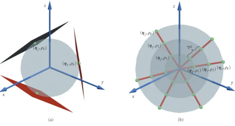
Figure1: The spherical trace transform.
2. THE SPHERICAL TRACE TRANSFORM
LetMbe a 3D model and f(x) the binary volumetric
func-tion ofM, wherex=[x,y,z]T, and
f(x)=
⎧ ⎨ ⎩
1 whenxlies within the 3D model’s volume,
0 otherwise.
(1)
Let us define planeΠ(η,ρ)= {x|xT·η=ρ}to be tangential
to the sphereSρwith radiusρand center at the origin, at the
point (η,ρ), whereη = [cosφsinθ, sinφsinθ, cosθ] is the
unit vector inR3, andρa real positive number (Figure 1(a)).
Additionally, let us define radius segment Λ(η,ρ) = {x |
x/|x| = η, ρ ≤ |x| < ρ+Δρ}, where Δρ is the length of
the radius segment (Figure 1(b)).
The intersection of Π(η,ρ) with f(x) produces a 2D
function f(a,b), (a,b∈Π(η,ρ)∩f(x)), which is then
sam-pled and its discrete form f(i,j), (i,j ∈ N) is produced.
Similarly, the intersection ofΛ(η,ρ) with f(x) produces a 1D
function ˇf(c) (c∈Λ(η,ρ)∩f(x)) which is also sampled and
its discrete form ˇf(i), (i∈N) is produced. These two forms
of data, f(i,j) and ˇf(i), will serve as input in the sequel. The “spherical trace transform,” proposed in this paper can be expressed using the general formulas
gs(T;F;h)=T
Fh(·),
ga(T;A;F;h)=T
AFh(·),
(2)
where
h(·)=
⎧ ⎪ ⎪ ⎪ ⎪ ⎨ ⎪ ⎪ ⎪ ⎪ ⎩
f(i,j), assuming representation using 2D planes
ˇ
f(i),
assuming representation using
radius segments
(3)
andF(η,ρ) denotes an “initial functional,” which can be
ap-plied to each f(i,j) or ˇf(i), that is,F(η,ρ) = F(f(i,j)) or
F(η,ρ)=F( ˇf(i)). The set ofF(η,ρ) is treated either as a
col-lection of spherical functions{Fρ(η)}
ρparameterized byρ,
or as a collection of radial functions{Fη(ρ)}ηparameterized
byη.
In the first case, a set of “spherical functionals”T(ρ) is
applied to eachFρ(η), producing a descriptor vectorg
s(T)=
T(Fρ(η)).
In the second case, a set of “actinic functionals”A(η)
is applied to eachFη(ρ), producing theA(η) = A(Fη(ρ)).
Then, theTfunctionals are applied toA(η), generating
an-other descriptor vectorga(T)=T(A(η)).
Let us now examine the conditions that must be satisfied by the functionals in order to produce rotation invariant de-scriptor vectors. Under a 3D object rotation governed by a
3D rotation matrixR, the pointsηwill be rotated:
η=R·η, (4)
therefore
x y z
(η2,ρ1)
(a)
x y
z 45Æ
(η2,ρ1)
(b)
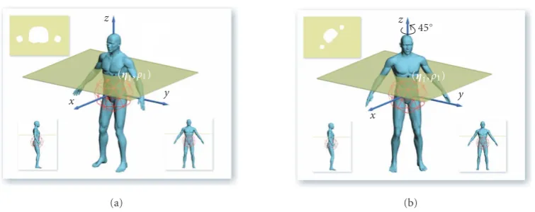
Figure2: Rotation off(x) rotatesF(η,ρ), without rotating the corresponding f(i,j) (upper left image). Thus,F(η2,ρ1)=F(η2,ρ1).
x y
z
(η1,ρ1)
(a)
x
y z
45Æ
(η1,ρ1)
(b)
Figure3: Rotation off(x) rotatesf(i,j) (upper left image) without causing a rotation of the point (η1,ρ1).
and thus, rotation invariantT functionals must be applied,
so thatT(F(η,ρ))=T(F(η,ρ)) (Figure 2).
In the specific case where the pointsηlie on the axis of
rotation the corresponding f(i,j) will be rotated (Figure 3),
that is,
f(i,j)=f(i,j) (6)
and thus, 2D rotation invariant functionals must be applied, so thatF(f(i,j)) =F(f(i,j)). Therefore, a general
solu-tion is given using 2D rotasolu-tion invariant funcsolu-tionalsF and
rotation invariant spherical functionalsT, producing
com-pletely rotation invariant descriptor vectors.
The functionals which satisfy the above-stated condi-tions, as initial, actinic, and spherical, will be briefly dis-cussed in the following section.
The advantage of this approach is threefold: firstly, the rotation normalization which hampers the performance of
the descriptors in most 3D search approaches, is avoided. Secondly, the possibility of constructing a large number of descriptor vectors is presented. Indeed, the recognition of 3D objects is facilitated when a large number of features are present and in fact, the more classes must be distinguished, the more features may be necessary. The proposed method permits the construction of a large number of invariant
fea-tures by defining a sufficient number ofF,A, andT
func-tionals. Thirdly, the use of theTfunctionals leads to the
def-inition of descriptor vectors with low dimensionality since
eachTfunctional produces a single number per concentric
sphere. Thus, a compact representation of the descriptor vec-tors is achieved, which in turn simplifies the comparison be-tween two models.
Another advantage of the proposed method is that it
overcomes the problem analyzed in [12, Section 5.2] that face
rotations are applied on an object at specific radius, an object
of totally different shape will be produced. Because of the
in-tegration over all shells of the same radius, all these methods
will produce identical descriptors for these totally different
objects. The proposed method will not be affected of such a
transformation, since in the case of decomposing the object’s volume in 2D planes, the planes will contain information of
the object in different radius. Moreover, the actinic
function-als will be applied on the results from the previous step, that all share the same angular position, thus information on the
different spheres will be combined. These two facts will
as-sure that objects, of totally different shape, produced from
transformations of independent rotations on an object, will not produce identical descriptors.
In the following a brief description of the functionals that were selected will be given.
2.1. Initial functionalsF
2.1.1. The “mutated” radial integration transform (RIT)
LetΛ(η,ρ)= {x|x/|x| =η, ρ≤ |x|< ρ+Δρ}be a radius segment (Figure 1(b)). Let also ˇft(i) be the discrete function, which is derived from ˇft(c). ˇft(c) is produced from the
in-tersection of f(x) with theΛ(ηt,ρt) which begins from the
point (ηt,ρt) and ends at the point (ηt,ρt+Δρ). Then, the
“mutated” radial integration transform RIT(η,ρ) [10] is
de-fined as:
RITηt,ρt
= N−1
i=0
ˇ
ft(i), (7)
wheret = 1,. . .,NR,NR is the total number of radius
seg-ments, andNis the total number of sampled points on each
line segment.
2.1.2. 1D Fourier transform
The 1D discrete Fourier transform of ˇft(i) is calculated,
pro-ducing the vectors DFt(k), wheret=1,. . .,NR,NRis the total
number of radius segments, andk =0,. . .,N−1,N is the
total number of sampled points on each radius segment. The
vectors contain only the firstK harmonic amplitudes. As a
result, the 1D DFT generatesKdifferent initial functionals.
2.1.3. The 3D Radon transform
LetΠ(η,ρ)= {x|xT·η=ρ}be a plane (Figure 1(a)). Let
also ft(i,j) be the discrete function, which is derived from
ft(a,b). The function ft(a,b) is produced from the intersec-tion of f(x) withΠ(ηt,ρt), which is tangential to the sphere
with radiusρtat the point (ηt,ρt). Then, the 3D radon
trans-formR(η,ρ) is defined as
Rηt,ρt
= N−1
i=0
N−1
j=0
ft(i,j), (8)
where t = 1,. . .,NR,NR is the total number of planes (≡
total number of radius segments), andN×Nare the sampled
points on each plane.
2.1.4. The Polar-Fourier transform
The discrete Fourier transform (DFT) is computed for each
ft(i,j), producing the vectors FTt(k,m), wherek,m=0,. . .,
N−1 andt=1,. . .,NR. Considering the firstK×M
har-monic amplitudes for each ft(i,j), the polar-DFT generates
K×Mdifferent initial functionals.
2.1.5. Hu moments
Moment invariants have become a classical tool for 2D
ob-ject recognition. They were firstly introduced by Hu [20],
who employed the results of the theory of algebraic
invari-ants [21] and derived the seven well-known Hu moments,φi,
i=1,. . ., 7, which are invariant to the rotation of 2D objects.
They are calculated for each ft(i,j) with spatial dimension
N×N, producing the vectors HUti, wherei = 1,. . ., 7 and
t=1,. . .,NR.
2.1.6. Zernike moments
Zernike moments are defined over a set of complex polyno-mials which forms a complete orthogonal set over the unit
disk and are rotation invariant. The Zernike momentsZkm
[22], wherek ∈N+,m ≤ k, are calculated for each f
t(i,j)
with spatial dimensionN×N, producing the vectorsZtkm.
2.1.7. Krawtchouk moments
Krawtchouk moments are a set of moments formed by using Krawtchouk polynomials as the basis function set.
Follow-ing the analysis in [23] and some specifications mentioned
in [24], they were computed for each ft(i,j) producing the
vectorsKtkm.
2.1.8. The 2D Polar wavelet transform
The 2D wavelet transform includes the convolution of the
two-dimensional function ft(i,j) with a pair of QMF filters,
followed by downsampling by a factor of two. In order to
produce rotation invariant features, ft(i,j) should be
trans-formed to the polar coordinate system, resulting in the Polar
wavelet transform [25]. In the first level of decomposition,
four different subbands are produced. The rotation
invari-ant functionals WTkmt are derived by computing an energy
signature for each subband (k,m =0, 1). In this paper, the
Daubechies D6 wavelet [26] was chosen as an appropriate
pair of filters.
Each of the aforementioned F functionals produces a
of values for each initial functionalF generates a function
F(η,ρ) whose domain consists of concentric spheres.
2.2. Actinic functionalsA
TheF(η,ρ) produced as above is now treated as a collection
of radial functionsFη(ρ) by restricting at differentη. Then,
the following set of “actinic functionals”Ai(η),i=1,. . ., 4,
is applied to eachFη(ρt):
(1) A1(η)=DF(Fη(ρt))=DFηk(ρt), (2) A2(η)=max{Fη(ρt)},
(3) A3(η)=max{Fη(ρt)} −min{Fη(ρt)},
(4) A4(η)=Nr
t=1|Fη(ρt)|,
whereFis the derivative ofF,t=1,. . .,Nrare sample points
on eachη, andNris their total number.
2.3. Spherical functionalsT
The set of functionalsT, which is applied to eachFρ(η) and
Ai(η), in order to produce the descriptor vector, includes
(1) T1(ω)=max{ω(ηj)},j=1,. . .,Ns,
(2) T2(ω)=Ns
j=1|ω(ηj)|,
(3) T3(ω)=Ns
j=1ω(ηj),
(4) T4(ω)=max{ω(ηj)} −min{ω(ηj)},j=1,. . .,Ns, (5) the amplitudes of the first L harmonics of the
spheri-cal Fourier transform (SFT), applied onω(ηj), which
are also called as the “rotationally invariant shape
de-scriptors”Al[27]. In the proposed method, for eachl,
l =1,. . .,L, the correspondingAlis a spherical
func-tionalT,
whereω(ηj) =Fρ(η
j) orω(ηj) =Ai(ηj),ωits derivative,
andNs=NR/Nc, whereNcis the total number of concentric
spheres. In our case,
ω(η)=
⎧ ⎪ ⎪ ⎪ ⎪ ⎪ ⎪ ⎪ ⎪ ⎪ ⎪ ⎪ ⎪ ⎪ ⎪ ⎪ ⎪ ⎪ ⎪ ⎪ ⎪ ⎪ ⎪ ⎪ ⎪ ⎪ ⎪ ⎪ ⎨ ⎪ ⎪ ⎪ ⎪ ⎪ ⎪ ⎪ ⎪ ⎪ ⎪ ⎪ ⎪ ⎪ ⎪ ⎪ ⎪ ⎪ ⎪ ⎪ ⎪ ⎪ ⎪ ⎪ ⎪ ⎪ ⎪ ⎪ ⎩
RITρ(η),
DFρk(η),
Rρ(η),
FTρkm(η),
HUρk(η),
Zkmρ (η),
Kkmρ (η),
WTρkm(η),
A(η).
(9)
Concluding this section, it should be noted that the total
number of spherical functionalsTused isL+ 4 for each
con-centric sphere.
3. DESCRIPTOR EXTRACTION PROCEDURE
3.1. Preprocessing
A 3D modelMis generally described by a 3D mesh. LetR×
R×Rbe the size of the smallest cube bounding the mesh. The
bounding cube is partitioned in (2·N)3equal cube shaped
voxelsuiwith centersvi=[xi,yi,zi], wherei=1,. . ., (2·N)3.
The size of each voxel is (R/(2·N))3. LetUbe the set of all
voxels inside the bounding cube andU1 ⊆ U, be the set of
all voxels belonging to the bounding cube and lying inside
M. Then, the discrete binary volume function f(vi) ofM, is
defined as
fvi
=
⎧ ⎨ ⎩
1 whenui∈U1,
0 otherwise. (10)
In order to achieve translation invariance, the center of mass of the model is first calculated. Then, the model is translated so that the center of mass coincides with the center of the bounding cube. Translation invariance follows.
To achieve scaling invariance, the maximum distance
dmaxbetween the center of mass and the most distant voxel,
where f(vi)=1, is calculated. Then, the translated f(vi) is
scaled so thatdmax = 1. At this point, scaling invariance is
also accomplished.
A coarser mesh is then constructed by combining every
eight neighboring voxelsui, to form a bigger voxelνk with
centersνk,k = 1. . .,N3. The discrete integer volume
func-tion f(νk) ofMis defined as
fνk
=
8
n=1
fvn
:un∈νk. (11)
Thus, the domain of f(νk) is [0,. . ., 8]. The procedure
described inSection 2is then applied to the function f(νk)
instead of the function f(x). Specifically,f(νk) is assumed to intersect with planes. Each plane is tangential to the sphere
with radiusρ at the pointB. Further, f(νk) is assumed to
intersect with radius segments.
In order to avoid possible sampling errors caused using the lines of latitude and longitude (since they are too much concentrated towards the poles), each concentric sphere is simulated by an icosahedron where each of the 20 main
tri-angles is iteratively subdivided into q equal parts to form
sub-triangles. The vertices of the subtriangles are the
sam-pled pointsBt. Their total numberNs, for each concentric
sphere (icosahedron)Cs, with radiusρs,s=1,. . .,Nc, where
Ncis the total number of concentric spheres, is easily seen to
be
Ns=10·q2+ 2. (12)
3.2. Descriptor extraction
Each function ft(a,b),t= 1,. . .,Ns, is quantized intoN×
domain of ft(i,j) is [0,. . ., 8]. Similarly, each function ft(c)
is quantized intoNsamples and its discrete form ˇft(i) is
pro-duced. The domain of ˇft(i) is [0,. . ., 8].
Then, the procedure described inSection 2is followed
for each functional F, producing the descriptor vectors
gs(T) = T(Fρt(ηt)) = D1F(l1), and ga(T) = T(A(ηt)) =
D2F(l2), wherel1=1,. . ., (L+ 4)·Nc,l2=1,. . ., (L+ 4)·4
andLis the total number of spherical harmonics. The
in-tegrated descriptor vector is DF(l) = [D1F(l1),D2F(l2)]T, wherel=1,. . .,{(L+ 4)·Nc+ (L+ 4)·4}.
The same procedure is followed for all F functionals,
producing the descriptor vectors DRIT(l), DDFk(l), DR(l),
DHUk(l),DFTkm(l),DZkm(l),DKkm(l), andDWTkm(l).
Our experiments presented in the sequel were performed
using the valuesNR =2562,Nc =20,L =26,K =8, and
N=64.
4. MATCHING ALGORITHM
Let A,B be two 3D models. Let also DA(k) = [DA1(k1),
DA2(k2)]T,DB(k) = [DB1(k1),DB2(k2)]T be two descriptor
vectors of the same kind D(k). The model descriptors are
compared in pairs using theirL1-distance:
D1similarity=
(
L+4)·Nc
k1=1
DA1(k1)−DB1(k1),
D2similarity=
(L+4)·4
k2=1
DA2(k2)−DB2(k2).
(13)
The overall similarity measure is determined by
Dsimilarity=a1·D1similarity+a2·D2similarity, (14)
wherea1,a2are descriptor vector percentage factors, which
are calculated as follows. Let us assume thatAbelongs to a
classC, which containsNCmodels. Let alsoNtotalbe the total
number of models contained in the database. Then the factor
a1is calculated as
a1=
NC
i=1di
Ntotal−NC
j=1 dj
, (15)
wherediis the L1-distance of the descriptor vectorDA1 of
the modelAfrom the descriptor vectorDA1of the modelA
which also belongs toC, anddjis theL1-distance of the
de-scriptor vectorDA1of the modelAfrom the descriptor
vec-torDA1
of the modelAwhich does not belong toC. The
combination, smalldiand bigdj, implies that the
descrip-tor vecdescrip-torDA1is good for the classC, in terms of successful
retrieved results. The percentage factora2is calculated
simi-larly taking into account the descriptor vectorDA2. Thena1
anda2are normalized so that 1/a1+ 1/a2=100.
Following the above approach, a large number of
descrip-tor vecdescrip-tors can be efficiently used, taking advantage of the
discriminative power of each descriptor vector per different
class.
Experiments have shown that a single descriptor vector does not outperform all the others, in terms of precision
re-call, in all different classes, thus using the percentage factors
we take advantage of the real discriminative power of each
descriptor vector per each different class. Such an approach
has not been reported so far in this research field.
4.1. Assigning weights to each class
In this section, a procedure for the calculation of weights characterizing the discriminative power of each descriptor
vector per different class is described.
LetDi(j) = [Di(1), . . ., Di(S)] be a descriptor vector,
wherei=1,. . .,Ntotal.Ntotalis the total number of 3D models
andSis the total number of descriptors per descriptor vector.
Let alsoCbe a class with descriptor vectors:
MC=
⎡ ⎢ ⎢ ⎢ ⎢ ⎢ ⎢ ⎢ ⎢ ⎢ ⎢ ⎢ ⎣
D1(1) . . . D1(k) . . . D1(S)
· · ·
Di(1) . . . Di(k) . . . Di(S)
· · ·
DNC(1) . . . DNC(k) . . . DNC(S)
⎤ ⎥ ⎥ ⎥ ⎥ ⎥ ⎥ ⎥ ⎥ ⎥ ⎥ ⎥ ⎦
, (16)
whereNCis the number of 3D models which belongs to class
C.
Then, thefeature vectorsfC1,. . .,fCk,. . .,fCS are formed, whereC=1,. . .,Nclass,fCk=[D1(k)· · ·Di(k)· · ·DNC(k)]T, andNclassis the total number of classes.
For eachfCk, the mean
μfCk =
1
NC NC
i=1
Di(k) (17)
and the variance
σ2 fCk =
1
NC NC
i=1
Di(k)2−μ fCk
2
(18)
are calculated. The magnitude of each weightWCk depends
on two factors.
(i) The compactness factorW(1): theW(1)factor provides
a measure of the compactness of thefCkfeature vector
for the classC. It is calculated by
WCk(1)=
σfCk
μfCk
. (19)
The lower the value ofWCk(1)the higher the weight of
(ii)The dissimilarity factorW(2): theW(2)factor provides
a measure of dissimilarity between the feature vector
fCk of the classC and the corresponding feature
vec-tor fC1k of the classC1. The higher the WCk(2) factor
the more dissimilar is thekth feature vector ofCclass
(fCk) when compared to thekth feature vectors of the
other classes. Specifically, for thekth feature vector of
Cth class, the number MCk of the descriptorsDn(k),
wheren∈([1,. . .,Nclass]−C), which do not belong to
[μfCk−σCk,μfCk+σCk] is calculated, and theW(2)factor
is evaluated using
WCk(2)= MCk
Ntotal−NC, (20)
whereNtotalis the total number of 3D models andNC
is the number of models of the Cth class. The final
weights are calculated by
WCk=C1
1−WCk(1)
+C2WCk(2), (21)
whereC1,C2∈[0, 1] are coefficients and
C1+C2=1. (22)
It is obvious that
0≤WCk≤1. (23)
It was experimentally found that best results were ob-tained forC1∈[0.2, 0.4] andC2∈[0.6, 0.8].
A 2D array of weights is then created, for all models in database,
W=
⎡ ⎢ ⎢ ⎢ ⎢ ⎢ ⎢ ⎢ ⎢ ⎢ ⎢ ⎣
W11 . . . W1k . . . W1S
· · ·
WC1 . . . WCk . . . WCS · · ·
WNclass1 . . . WNclassk . . . kNclassS
⎤ ⎥ ⎥ ⎥ ⎥ ⎥ ⎥ ⎥ ⎥ ⎥ ⎥ ⎦
, (24)
whereWCkis the weight of thekth descriptor of theCth class.
The weight matrix will be used to improve the performance of matching methods. In the following sections, two match-ing methods are described, where the contribution of weights to the final results is noticeable.
4.2. First weight-based matching algorithm: “weight method 1” (WM1)
LetQbe a query model andAa model from the database to
be compared withQ. The model descriptors are compared in
pairs using the following formula (L1-distance):
L1=
S
k=1
WCkDQ(k)−DA(k), (25)
whereDQ(k) is thekth descriptor of the query modelQand
DA(k) is thekth descriptor of the modelAthat belongs to
classC. In this method, bothDQ(k) andDA(k) descriptors
are assigned the weightWCkof classC.
4.3. Second weight-based matching algorithm: “weight method 2” (WM2)
Let now Ai (i = 1,. . .,Ntotal) be a model of the database,
whereNtotalis the total number of models in the database.
In this method, theL1-distance betweenQandAimodels is
calculated. However, in this case,DQ(k) andDAi
(k) descrip-tors are not assigned the same weights.
Specifically, for a queryQ,Nclassdifferent cases are
con-sidered. For thenth case (n=1,. . .,Nclass) it is assumed that
the query Qbelongs to class n, so that its DQ(k)
descrip-tor vecdescrip-tor is assigned the correspondingWn(k) weight vector
(nth raw of the weight matrix). For each casen, for each pair
ofQandAimodels, theL1-distance is calculated according
to the following formula:
L1in=
S
k=1
WnkDQ(k)−W
CkDAi(k), (26)
wheren=1,. . .,Nclassandi=1,. . .,Ntotal. In allNclasscases,
the modelAiis assigned the sameW
C(k) weight vector (Cth raw of the weight matrix).
The final matching between Q and Ai is achieved by
choosing only one casen(out ofNclass). The queryQis
as-signed the same weightsWn(k) for allL1idistances. The
se-lection of the optimal casenis based on the following
proce-dure.
For each casen, allL1i
ndistances between the query Q
and the modelsAiof the database (i=1,. . .,Ntotal) are sorted in ascending order. In order to evaluate the homogeneity of the retrieved results at the first positions of the ranking list,
the popular “Gini” indexI(n) [28] is used, as a measure of
impurity. The smaller the Gini index, the lower the hetero-geneity of the retrieved results:
I(n)=1− Nclass
C=1 p2
C, (27)
wherepCis the fraction of models retrieved at the firstk
po-sitions of the ranking list that belong to classC, divided with
k. Notice thatI(n)=0 if all the retrieved models belong to
the same class. The casen(out ofNclass) with the lowest Gini
impurity index is used for the final matching betweenQand
1 0.9 0.8 0.7 0.6 0.5 0.4 0.3 0.2 0.1 0
Recall 0
0.1 0.2 0.3 0.4 0.5 0.6 0.7 0.8 0.9 1
P
recision
Krawtchouk Zernike Polar-Fourier Wavelets HU DF
RIT 3D-Radon GEDT REXT LFD Precision vs. recall of all classes without weights
(a)
1 0.9 0.8 0.7 0.6 0.5 0.4 0.3 0.2 0.1 0
Recall 0
0.1 0.2 0.3 0.4 0.5 0.6 0.7 0.8 0.9 1
P
recision
Krawtchouk Zernike Polar-Fourier Wavelets HU DF
RIT 3D-Radon GEDT REXT LFD Precision vs. recall of all classes without weights
(b)
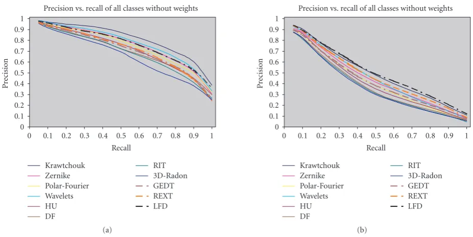
Figure4: Precision-recall curves diagram using the new database (a) and the Princeton database (b).
IfT >1 lowest impurity indices are encountered, a sec-ond measure is taken into account.
Letni = arg minI(n),i = 1,. . .,T. For eachni, let the
majority of the models retrieved at the firstkpositions of the
ranking list belong to classCi. The numberMniof the models
of categoryCi, from the first position to the position that a
model of a category other than Ci occurs, is calculated for
eachni. The fractionMni/NCi, whereNCiis the total number
of models in classCi, is the second measure for the selection
of the best value ofni. The value leading to the largest value of
the fraction above is the one selected for the final matching, that is,ni=arg max{Mni/NCi}.
5. EXPERIMENTAL RESULTS
The proposed method was tested using two different
databases. The first one, formed in Princeton University [29]
consists of 907 3D models classified into 35 main categories. Most are further classified into subcategories, forming 92 cat-egories in total. This classification reflects primarily the
func-tion of each object and secondarily its form [30]. The
sec-ond one was compiled from the Internet by us, it consists of
544 3D models from different categories and was also used in
[31]. The VRML models were collected from the World Wide
Web so as to form 13 more balanced categories: 27 animals, 17 spheroid objects, 64 conventional airplanes, 55 delta air-planes, 54 helicopters, 48 cars, 12 motorcycles, 10 tubes, 14 couches, 42 chairs, 45 fish, 53 humans, and 103 other mod-els. This choice reflects primarily the shape of each object and secondarily its function. The average numbers of vertices and triangles of the models in the new database are 5080 and 7061, respectively.
To evaluate the proposed method, each 3D model was used as a query object. Our results were compared with those
of the following methods, which have been reported [29] as
the best-known shape matching methods that produce the best retrieval results.
(i) Gaussian Euclidean distance transform (GEDT): it is based on the comparison of a 3D function, whose value at each point is given by composition of a Gaus-sian with the Euclidean distance transform of the sur-face [12].
(ii) Light field descriptor (LFD): uses a representation of a model as a collection of images rendered from uniformly sampled positions on a view sphere. The distance between two descriptors is defined as the
min-imumL1-difference, taken over all rotations and all
pairings of vertices on two dodecahedra [7].
(iii) Radialized spherical extent function (REXT): uses a
col-lection of spherical functions giving the maximal dis-tance from center of mass as a function of spherical
angle and radius [32].
It is noted that we did not implement the above methods. All executables were taken from the home pages of the authors of [7,12,32].
The retrieval performance was evaluated in terms of “precision” and “recall,” where precision is the proportion of the retrieved models that are relevant to the query and recall is the proportion of relevant models in the entire database that are retrieved in the query.
Experimental results have shown that the following de-scriptor vectors should be selected, for achieving best per-formance, in the case of multiple descriptor vector
ex-traction: FT = {FT00, FT01, FT10}, HU = {HU0, HU3},
Z = {Z00,Z11,Z20,Z31}, K = {K00,K01,K02,K11}, WT = {WT00, WT01, WT10, WT11}, and DF= {DF2, DF4}.
1 0.9 0.8 0.7 0.6 0.5 0.4 0.3 0.2 0.1 0
Recall 0
0.1 0.2 0.3 0.4 0.5 0.6 0.7 0.8 0.9 1
P
recision
Kraw-Zern Kraw-Wavelet Kraw-HU HU-Pol.Fourier
GEDT REXT LFD All
Precision vs. recall of all classes without weights
(a)
1 0.9 0.8 0.7 0.6 0.5 0.4 0.3 0.2 0.1 0
Recall 0
0.1 0.2 0.3 0.4 0.5 0.6 0.7 0.8 0.9 1
P
recision
Kraw-Zern Kraw-Wavelet Kraw-HU HU-Pol.Fourier
GEDT REXT LFD All Precision vs. recall of all classes without weights
(b)
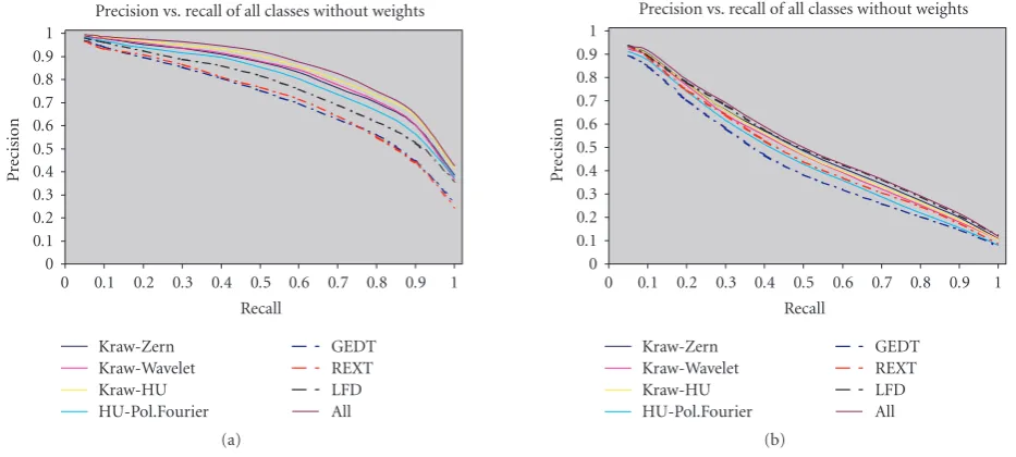
Figure5: Precision-recall curves diagram: some of the best descriptor vector combinations, using the new database (a) and the Princeton database (b).
1 0.9 0.8 0.7 0.6 0.5 0.4 0.3 0.2 0.1 0
Recall 0
0.1 0.2 0.3 0.4 0.5 0.6 0.7 0.8 0.9 1
P
recision
Polar-Fourier Zernike
Precision vs. recall of class “Helicopters”
Figure6: Comparison of the efficiency of the Polar-Fourier-based
descriptor vector against the Zernike moments-based descriptor vector for a class of the new database.
database. It is clear that the proposed method outperforms all others using the integrated descriptor vector and calculat-ing the percentage factors for each descriptor vector. Addi-tionally, other descriptor vectors produced by Krawtchouk moments, Zernike moments, the Polar wavelet transform, the Polar-Fourier transform, and the HU moments out-perform or are competitive with the other known
state-of-the-art methods.Figure 4(b)illustrates the results using the
Princeton database. In this database, the LFD method pro-vides the best retrieval precision, and only the descriptor
vec-tors based on the Krawtchouk moments and on the Zernike moments are competitive.
InFigure 5, some of the best combinations which sig-nificantly improve the retrieval performance of the pro-posed method are shown. The retrieval performance is im-proved due to the fact that a single descriptor vector does
not outperform all the others in all different classes, thus
us-ing the percentage factors (see Section 4) we can take
ad-vantage of the real discriminative power of each
descrip-tor vecdescrip-tor per each different class. An example is
illus-trated in Figure 6 where the descriptor vector based on
Polar-Fourier transform is seen to outperform the descrip-tor vecdescrip-tor based on Zernike moments in class “helicopters” of the new database. However, the overall retrieval perfor-mance of the descriptor vector based on Zernike moments
is better (Figure 4(a)). Figure 5 illustrates the results
ob-tained using all the descriptor vectors and their percentage factors. It is clear that the proposed method outperforms all known methods in both databases. However, this pro-cedure is time consuming, thus, simpler alternatives such
as the combination Krawtchouk-Zernike, or the
combina-tionKrawtchouk-Hu, can be used instead, with very good re-sults.
Figure 7depicts the precision-recall diagram using the “weight method 1” (WM1) using the new database and the Princeton database. It is obvious that the retrieval results
were improved significantly. In Figure 8 some of the best
combinations which significantly improve the retrieval per-formance of the proposed method are shown.
1 0.9 0.8 0.7 0.6 0.5 0.4 0.3 0.2 0.1 0
Recall 0
0.1 0.2 0.3 0.4 0.5 0.6 0.7 0.8 0.9 1
P
recision
Krawtchouk Zernike Polar-Fourier Wavelets HU DF
RIT 3D-Radon GEDT REXT LFD Precision vs. recall of all classes using WM1
(a)
1 0.9 0.8 0.7 0.6 0.5 0.4 0.3 0.2 0.1 0
Recall 0
0.1 0.2 0.3 0.4 0.5 0.6 0.7 0.8 0.9 1
P
recision
Krawtchouk Zernike Polar-Fourier Wavelets HU DF
RIT 3D-Radon GEDT REXT LFD Precision vs. recall of all classes using WM1
(b)
Figure7: Precision-recall curves diagram using the weight method 1 for the new database (a) and for the Princeton database (b).
1 0.9 0.8 0.7 0.6 0.5 0.4 0.3 0.2 0.1 0
Recall 0
0.1 0.2 0.3 0.4 0.5 0.6 0.7 0.8 0.9 1
P
recision
Kraw-Zern Kraw-Wavelet Kraw-HU HU-Pol.Fourier
GEDT REXT LFD All Precision vs. recall of all classes using WM1
(a)
1 0.9 0.8 0.7 0.6 0.5 0.4 0.3 0.2 0.1 0
Recall 0
0.1 0.2 0.3 0.4 0.5 0.6 0.7 0.8 0.9 1
P
recision
Kraw-Zern Kraw-Wavelet Kraw-HU HU-Pol.Fourier
GEDT REXT LFD All Precision vs. recall of all classes using WM1
(b)
Figure8: Precision-recall curves diagram some of the best descriptor vector combinations, using the weight method 1 for the new database (a) and for the Princeton database (b)
the new database where all of the proposed descriptor vectors outperform the others.
InFigure 10some of the best combinations which sig-nificantly improve the retrieval performance of the proposed method are depicted.
Figure 11illustrates the results of the experiments
per-formed in the new database using different dimensionality
for the RIT-based descriptor vector changing the numberL
of the harmonics of the spherical Fourier transform. It is ob-vious that an increase in precision is observed if the number
of spherical harmonicsLincreases fromL =21 toL=26.
However, there was no commensurate modification in
preci-sion for values ofLhigher than 26, while the time needed for
the extraction of the descriptor vectors as well as for carrying out the matching procedure increased sharply.
6. CONCLUSIONS
1 0.9 0.8 0.7 0.6 0.5 0.4 0.3 0.2 0.1 0
Recall 0
0.1 0.2 0.3 0.4 0.5 0.6 0.7 0.8 0.9 1
P
recision
Krawtchouk Zernike Polar-Fourier Wavelets HU DF
RIT 3D-Radon GEDT REXT LFD Precision vs. recall of all classes using WM2
(a)
1 0.9 0.8 0.7 0.6 0.5 0.4 0.3 0.2 0.1 0
Recall 0
0.1 0.2 0.3 0.4 0.5 0.6 0.7 0.8 0.9 1
P
recision
Krawtchouk Zernike Polar-Fourier Wavelets HU DF
RIT 3D-Radon GEDT REXT LFD Precision vs. recall of all classes using WM2
(b)
Figure9: Precision-recall curves diagram using the weight method 2 for the new database (a) and for the Princeton database (b).
1 0.9 0.8 0.7 0.6 0.5 0.4 0.3 0.2 0.1 0
Recall 0
0.1 0.2 0.3 0.4 0.5 0.6 0.7 0.8 0.9 1
P
recision
Kraw-Zern Kraw-Wavelet Kraw-HU HU-Pol.Fourier
GEDT REXT LFD All Precision vs. recall of all classes using WM2
(a)
1 0.9 0.8 0.7 0.6 0.5 0.4 0.3 0.2 0.1 0
Recall 0
0.1 0.2 0.3 0.4 0.5 0.6 0.7 0.8 0.9 1
P
recision
Kraw-Zern Kraw-Wavelet Kraw-HU HU-Pol.Fourier
GEDT REXT LFD All Precision vs. recall of all classes using WM2
(b)
Figure10: Precision-recall curves diagram some of the best descriptor vector combinations, using the weight method 2 for the new database (a) and for the Princeton database (b).
the volume of the 3D model producing a new domain of concentric spheres. In this new domain, a new set of func-tionals is applied, resulting in a completely rotation invari-ant descriptor vector, which is used for 3D model match-ing. Further, a novel technique, where weights are assigned to the descriptors, is introduced, which improves significantly
the retrieval results. Experiments were performed using two
different databases and the results of the proposed method
1 0.9 0.8 0.7 0.6 0.5 0.4 0.3 0.2 0.1 0
Recall 0
0.1 0.2 0.3 0.4 0.5 0.6 0.7 0.8 0.9 1
P
recision
L=21 L=31
L=26 L=36 Precision vs. recall of all classes
Figure11: Comparison of the efficiency of RIT-based descriptor
vectors using different dimensionality, in terms of precision-recall diagram using the new database.
ACKNOWLEDGMENTS
This work was supported by the ALTAB23D project of the Greek Secretariat of Research and Technology and by the CATER EC IST project.
REFERENCES
[1] 3D Cafe,http://www.3Dcafe.com.
[2] The Protein Data Bank,http://www.rcsb.org.
[3] I. Kolonias, D. Tzovaras, S. Malassiotis, and M. G. Strintzis, “Fast content-based search of VRML models based on shape descriptors,”IEEE Transactions on Multimedia, vol. 7, no. 1, pp. 114–126, 2005.
[4] R. Ohbuchi, T. Otagiri, M. Ibato, and T. Takei, “Shape-similarity search of three-dimensional models using param-eterized statistics,” inProceedings of the 10th Pacific Conference on Computer Graphics and Applications, pp. 265–274, Beijng, China, October 2002.
[5] R. Osada, T. Funkhouser, B. Chazelle, and D. Dobkin, “Match-ing 3D models with shape distributions,” inProceedings of the International Conference on Shape Modelling and Applications (SMI ’01), pp. 154–166, Genova, Italy, May 2001.
[6] R. Osada, T. Funkhouser, B. Chazelle, and D. Dobkin, “Shape distributions,”ACM Transactions on Graphics, vol. 21, no. 4, pp. 807–832, 2002.
[7] D.-Y. Chen, X.-P. Tian, Y.-T. Shen, and M. Ouhyoung, “On visual similarity based 3D model retrieval,”Computer Graphics Forum, vol. 22, no. 3, pp. 223–232, 2003.
[8] D. V. Vrani´c and D. Saupe, “Description of 3D-shape using a complex function on the sphere,” inProceedings of the IEEE International Conference on Multimedia and Expo (ICME ’02), vol. 1, pp. 177–180, Lausanne, Switzerland, August 2002. [9] D. V. Vrani´c, D. Saupe, and J. Richter, “Tools for 3D-object
re-trieval: Karhunen-Loeve transform and spherical harmonics,” inProceedings of the 4th IEEE Workshop on Multimedia Signal Processing (MMSP ’01), pp. 293–298, Cannes, France, October 2001.
[10] P. Daras, D. Zarpalas, D. Tzovaras, and M. G. Strintzis, “Gener-alized radon transform based 3D feature extraction for 3D ob-ject retrieval,” inProceedings of the 5th International Workshop on Image Analysis for Multimedia Interactive Services (WIAMIS ’04), Lisboa, Portugal, April 2004.
[11] B. Horn, H. Hilden, and S. Negahdaripour, “Closed-form so-lution of absolute orientation using orthonormal matrices,” Journal of the Optical Society of America, vol. 5, no. 7, pp. 1127– 1135, 1988.
[12] M. Kazhdan, T. Funkhouser, and S. Rusinkiewicz, “Rotation invariant spherical harmonic representation of 3D shape de-scriptors,” inProceedings of the Eurographics Symposium on Ge-ometry Processing, pp. 156–164, Aachen, Germany, June 2003. [13] M. Hilaga, Y. Shinagawa, T. Kohmura, and T. L. Kunii, “Topol-ogy matching for fully automatic similarity estimation of 3D shapes,” inProceedings of the 28th Annual Conference on Com-puter Graphics and Interactive Techniques (SIGGRAPH ’01), pp. 203–212, Los Angeles, Calif, USA, August 2001.
[14] MPEG Video Group, “MPEG-7 visual part of eXperimenta-tion model (version 9.0),” in Proceedings of the 55th Mpeg Meeting, Pisa, Italy, 2001, ISO/MPEG N3914.
[15] T. Funkhouser, P. Min, M. Kazhdan, et al., “A search engine for 3D models,”ACM Transactions on Graphics, vol. 22, no. 1, pp. 83–105, 2003.
[16] M. Novotni and R. Klein, “3D Zernike descriptors for content based shape retrieval,” inProceedings of the 8th ACM Sympo-sium on Solid Modeling and Applications, pp. 216–225, Seattle, Wash, USA, June 2003.
[17] N. Canterakis, “3D Zernike moments and Zernike affine in-variants for 3D image analysis and recognition,” inProceedings of the 11th Scandinavian Conference on Image Analysis, Kanger-lussuaq, Greenland, June 1999.
[18] M. T. Suzuki, “A web-based retrieval system for 3D polygonal models,” inProceedings of the Joint 9th IFSA World Congress and 20th NAFIPS International Conference, vol. 4, pp. 2271– 2276, Vancouver, Canada, July 2001.
[19] A. Kadyrov and M. Petrou, “The trace transform and its ap-plications,”IEEE Transactions on Pattern Analysis and Machine Intelligence, vol. 23, no. 8, pp. 811–828, 2001.
[20] M.-K. Hu, “Visual pattern recognition by moment invariants,” IEEE Transactions on Information Theory, vol. 8, no. 2, pp. 179–187, 1962.
[21] G. B. Gurevich,Foundations of the Theory of Algebraic Invari-ants, Noordhoff, Groningen, The Netherlands, 1964. [22] A. Padilla-Vivanco, A. Martinez-Ramirez, and F.
Granados-Agustin, “Digital image reconstruction by using Zernike mo-ments,” in Optics in Atmospheric Propagation and Adaptive Systems VI, vol. 5237 of Proceedings of SPIE, pp. 281–289, Barcelona, Spain, September 2004.
[23] P.-T. Yap, R. Paramesran, and S.-H. Ong, “Image analysis by Krawtchouk moments,”IEEE Transactions on Image Process-ing, vol. 12, no. 11, pp. 1367–1377, 2003.
[24] M. R. Teague, “Image analysis via the general theory of mo-ments,”Journal of the Optical Society of America, vol. 70, no. 8, pp. 920–930, 1980.
[25] C.-M. Pun and M.-C. Lee, “Log-polar wavelet energy signa-tures for rotation and scale invariant texture classification,” IEEE Transactions on Pattern Analysis and Machine Intelligence, vol. 25, no. 5, pp. 590–603, 2003.
[27] D. W. Ritchie,Parametric protein shale recognition, Ph.D. the-sis, University of Aberdeen, Scotland, UK, 1998.
[28] L. E. Raileanu and K. Stoffel, “Theoretical comparison be-tween the gini index and information gain criteria,”Annals of Mathematics and Artificial Intelligence, vol. 41, no. 1, pp. 77– 93, 2004.
[29] P. Shilane, P. Min, M. Kazhdan, and T. Funkhouser, “The Princeton Shape Benchmark,” inProceedings of the Shape Mod-eling International (SMI ’04), pp. 167–178, Genova, Italy, June 2004.
[30] Princeton Shape Benchmark, http://shape.cs.princeton.edu/ search.html.
[31] P. Daras, D. Zarpalas, D. Tzovaras, and M. G. Strintzis, “Shape matching using the 3D radon transform,” inProceedings of the 2nd International Symposium on 3D Data Processing, Visual-ization, and Transmission (3DPVT ’04), pp. 953–960, Thessa-loniki, Greece, September 2004.
[32] D. V. Vrani´c, “An improvement of rotation invariant 3D-shape descriptor based on functions on concentric spheres,” in Pro-ceedings of the IEEE International Conference on Image Process-ing (ICIP ’03), vol. 3, pp. 757–760, Barcelona, Spain, Septem-ber 2003.
Dimitrios Zarpalas was born in Thessa-loniki, Greece, in 1980. He is a Ph.D. can-didate at Northeastern University. He re-ceived the Diploma degree and the M.S. de-gree in electrical and computer engineer-ing from the Aristotle University of Thes-saloniki, Greece, in 2003, the Pennsylvania State University, USA, in 2006, respectively. His main research interests include search and retrieval of 3D objects, 3D object
recog-nition, and medical image processing. He is a Member of the Tech-nical Chamber of Greece.
Petros Daraswas born in Athens, Greece, in 1974. He is a Researcher Grade D’ at the Informatics and Telematics Institute. He received the Diploma degree in electrical and computer engineering, the M.S. degree in medical informatics, and the Ph.D. de-gree in electrical and computer engineer-ing from the Aristotle University of Thes-saloniki, Greece, in 1999, 2002, and 2005, respectively. His main research interests
in-clude computer vision, search and retrieval of 3D objects, the MPEG-4 standard, peer-to-peer technologies, and medical infor-matics. He has been involved in more than 10 European and na-tional research projects. He is a Member of the Technical Chamber of Greece.
Apostolos Axenopouloswas born in Thes-saloniki, Greece, in 1980. He is an Associate Researcher at the Informatics and Telemat-ics Institute. He received the Diploma de-gree in electrical and computer engineer-ing and the M.S. degree in advanced com-puting systems from the Aristotle Univer-sity of Thessaloniki, Greece, in 2003 and 2006, respectively. His main research inter-ests include 3D content-based search and
retrieval. He is a Member of the Technical Chamber of Greece.
Dimitrios Tzovarasreceived the Diploma degree in electrical engineering and the Ph.D. degree in 2D and 3D image com-pression from Aristotle University of Thes-saloniki, ThesThes-saloniki, Greece, in 1992 and 1997, respectively. He is a Senior Researcher in the Informatics and Telematics Institute of Thessaloniki. Prior to his current po-sition, he was a Senior Researcher on 3D imaging at the Aristotle University of
Thes-saloniki. His main research interests include virtual reality, assistive technologies, 3D data processing, medical image communication, 3D motion estimation, and stereo and multiview image sequence coding. His involvement with those research areas has led to the coauthoring of more than 35 papers in refereed journals and more than 80 papers in international conferences. He has served as a reg-ular Reviewer for a number of international journals and confer-ences. Since 1992, he has been involved in more than 40 projects in Greece, funded by the EC, and the Greek Secretariat of Research and Technology. He is an Associate Editor of the EURASIP Journal on Advances in Signal Processing and a Member of the Technical Chamber of Greece.
Michael G. Strintzisreceived the Diploma degree in electrical engineering from the National Technical University of Athens, Athens, Greece, in 1967, and the M.A. and Ph.D. degrees in electrical engineer-ing from Princeton University, Princeton, NJ, in 1969 and 1970, respectively. He then joined the Electrical Engineering Depart-ment at the University of Pittsburgh, Pitts-burgh, Penn, where he served as Assistant