4663
INTERACTIVE
DIGITAL PLOTTER
Please Check for
instruction manual, may cause interference to radio communications. It has been tested to comply with the limits for Class A computing devices pursuant to SubpartJor Part 15 of FCC Rules, which are designed to provide reasonable protection against such interference when operated in a commercial environment. Operation of this equipment in a residential area is likely to cause interference in which case the users at thier own expense will be required to take whatever measures may be required to correct the interference.
Copyright () 1982 by Tektronix, Inc., Beaverton, Oregon. Printed in the United States of America. All rights reserved. Contents of this publication may not be reproduced in any form without permission of Tektronix, Inc.
This instrument, in whole or in part, may be protected by one or more U.S. or foreign patents or patent applications. Information provided upon request by Tektronix, Inc., PO. Box 500, Beaverton, Oregon 97077
This manual supports the following versions of this product: Serial Numbers 8060100 and up.
REV DATE
DESCRIPTION
JAN 1982 Original Issue. This manual and the 4663 Programmer's Reference Manual (070-3806-00)
replace the original 4663 Operator's Manual (070-2670-00). This manual also replaces an October 1981 preliminary version (061·2637-00).
JUL1982 Revised: page 1-1.
Section 1
Section 2
GENERAL INFORMATION Page
About This Manual 1-1
Related Documentation '" 1-1
Major Features of the 4663 Interactive Digital Plotter 1-2
Options to the 4663 Plotter 1-2
Standard Accessories 1-3
Optional Accessories 1-3
GETTING STARTED
Introduction to the Plotter 2-2
Operator's Installation Check 2-4
Procedure 2-4
Using the Parameter Entry Card 2-6
Installing Media and Pens 2-8
Loading Sheet Media 2-8
Pen Installation 2-9
Run Self-Test 2-10
Using the Front Panel Controls 2-12
Operator's Check Procedure 2-12
Front Panel Operations Index 2-13
Check Procedure 2-13
Lower a Pen to the Paper and Exercise the
Joystick 2-1 3
Change the Pen Selection " 2-13 Locate the Upper-Right Corner of the Page 2-14 Locate the Upper-Right Corner of the Viewport. 2-14 Select the Mark Viewport Function 2-14 Select the Outline Viewport Function 2-14 Select a Different Page Size 2-15 Select a New Page Orientation 2-1 5 Change the Parameter Entry Card 2-1 5
Set a New Viewport 2-15
Change the Paper in Sheet Mode '" 2-16 Change the Paper in Roll Mode 2-16 Reposition the Page " " 2-16
Define a Page Size 2-17
Pen Controls 3-2
Control Matrix 3-3
Operating the Interface Switches 3-3 Interface Switches - Serial Installations 3-3 Interface Switches - GPIB Installations 3-5 Operating the SHIFT and FUNCTION Switches 3-6 RESET Switch Indications and Functions .. , 3-8
Reset Light Indications 3-8
Error Reset Function 3-8
Data Reset Function 3-8
Initialize Function. . . .. . 3-9 MEDIA Switch Indications and Functions 3-10
Media Light Indications 3-10
Media Change Function.. . 3-10
Manual Motion Function 3-11
Form Length Function 3-11
PLOT CONTROL Switch Indications and Functions 3-12 Plot Control Light Indications 3-12
Pause Function 3-12
Outline Viewport Function 3-12
Mark Viewport Function 3-13
LOWER LEFT and UPPER RIGHT Switches, Indications,
and Functions 3-13
LOWER LEFT and UPPER RIGHT Switch
Indications , 3-13
Locate Functions 3-13
Set Page Function (Repositioning the Page) 3-14 Set Page Function (Setting Page Size) 3-14 Set Viewport Lower Left and Upper Right
Functions 3-15
POINT Switch Indications and Functions
(Digitization) 3-16
Point Light Indications 3-16
Parameter Entry Card Line Descriptions 3-18 Parameter Setup Select Line 3-20
Media Group 3-20
Media Form Line 3-21
Initial Page Size Line 3-21
Initial Page Format Line 3-22
Page Orientation Line 3-23
Initial Aspect Ratio Line 3-23
Initial Axis Orientation Line 3-23
Line Quality Line 3-25
Pen Group 3-26
Pen Parameter Access Line 3-26
Pen Type Line 3-26
Pen Pressure Line 3-26
Pen Velocity Limit Line 3-26
Alpha Character Quality Line 3-27
Interface Select Line 3-28
Initial Command/Response Format Line 3-28
GPIB Group 3-30
GPIB Device Address Line 3-30
Interface Mode Line 3-30
Interface Functions Line 3-30
Serial Interface Group 3-30
Serial Device Address Line 3-31
Receive Baud Rate Line 3-31
Transmit Baud Rate Line 3-31
Transmit Baud Rate Limit Line 3-31
Character Format Line 3-31
Receive ParitylTransmit Parity Line 3-32 Communications Control Mode Line 3-32
DC1 /DC3 Control Line 3-32
Interface Functions Line 3-33
Attention Character Line 3-33
Output Terminator Line 3-33
Error Data Line 3-34
Section 5
Appendix A Appendix B Appendix C Appendix D
Plastic Hard-Tip Pens 4-3
Wet-Ink Pens 4-3
Inks for Wet-Ink Pens 4-3
Media Types 4-3
Loading Sheet Media 4-4
Using Roll Media , .. 4-4
Advancing Roll Media 4-4
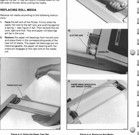
Using the Paper-Tear Bar 4-6
Replacing Roll Media 4-6
Pen Installation 4-7
Parameter Entry Card Pen Group Settings 4-8 Sheet Mode Pen Installation Procedure 4-8 Roll Mode Pen Installation Procedure 4-9
Pen Pressure Adjustments 4-9
Line Quality Considerations 4-10
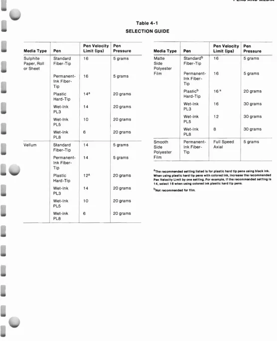
Selection Guide 4-10
Pen Maintenance. . 4-12
Storing Pens. .. . 4-12
Checking Tips for Wear , 4-12
Cleaning Wet-Ink Pens 4-12
Filling Wet-Ink Pens 4-15
Starting Wet-Ink Pen Flow 4-16
MAINTENANCE
Cleaning the Platen and the Case 5-1 Paper-Drive Mechanism Adjustments 5-2
Paper Width Adjustment. 5-2
Lateral Paper-Drive Mechanism Adjustment 5-3 Firmware Version and Memory Status Information 5-3
CHARACTERISTICS
DEFAULT PAGE, VIEWPORT, AND WINDOW COORDINATES ERROR TYPES
Figure Description Page 1-1 2-1 2-2 2-3 2-4 2-5 2-6 2-7 2-8 2-9 3-1 3-2 3-3 3-4 3-5 3-6 3-7 3-8 3-9 3-10 3-11 3-12 4-1 4-2 4-3 4-4 4-5 4-6 4-7 4-8 4-9 4-10 4-11 4-12 4-13 4-14 4-15 4-16 4-17 4-18 5-1 5-2 A-1
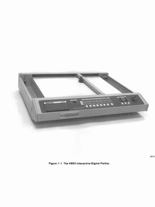
The 4663 Interactive Digital Plotter viii
Introduction to the Plotter 2-3
Interface Cable Connections 2-5
Parameter Entry Card Setups 2-7
Positioning Media on the Platen 2-8
Installing a Pen 2-9
Test Pattern Drawn by Self-Test Feature 2-11
Front Panel Switches 2-12
Page Positioning 2-17
Mirror, Upside-Down Mirror, and Upside-Down Image Plots 2-19 Front Panel Controls and Indicators 3-1
Control Matrix 3-3
INTERFACE Switch Selections for the Serial Interface 3-4 INTERFACE Switch Selections for the GPIB Interface 3-5
SHIFT and FUNCTION Switches 3-6
Parameter Entry Module 3-17
Parameter Entry Card 3-19
Page Orientation (for C-Size Drafting) 3-22 Viewports for Different Initial Aspect Ratios 3-24
Axis Orientations 3-25
NORMAL and ENHANCED Characters 3-27
Test Pattern Produced by Self Test Feature 3-35
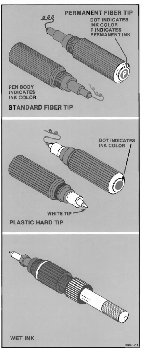
4663 Pens 4-2
Positioning Media on the 4663 Platen 4-5
Using the Paper- Tear Bar 4-6
Replacing Roll Media 4-6
The 4663 Pen Carriage 4-7
Removing 4663 Pen From the Pen Holder 4-8 Installing 4663 Pen Into the Pen Holder 4-8
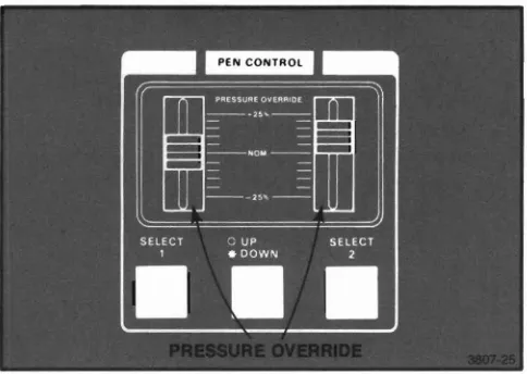
PRESSURE OVERRIDE Adjustments 4-9
Good and Worn Wet-Ink Pen Tips 4-13
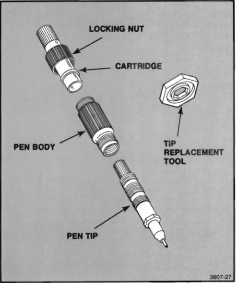
Dissassembling the 4663 Wet-Ink Pen 4-13 Using the Pressure/Suction Bulb to Clean Pens 4-14 Using the Ultrasonic Tank to Clean Pen Tips 4-14
Conserving Cleaning Fluid " 4-14
Removing the Wet-Ink Pen Locking Nut , , 4-15 Removing Excess Ink From the Wet-Ink Pen 4-15
Filling the Ink Cartridge 4-15
Starting Ink Flow by Tapping 4-16
Starting Ink Flow with the Pressure/Suction Bulb , .. 4-16
Paper Width Adjustment. 5-2
Lateral Paper-Drive Mechanism Adjustment 5-3
Table Description Page
3-1 3-2 3-3 3-4 4-1 A-1 A-2 A-3 A-4 A-5 C-1 C-2
Default Pen Pressure and Pen Velocity 3-26 Interface Select Line Definitions 3-28 Command/Response Formats - Serial. 3-29
Command/Response Formats - GPIB 3-29
Selection Guide '" '" . 4-11
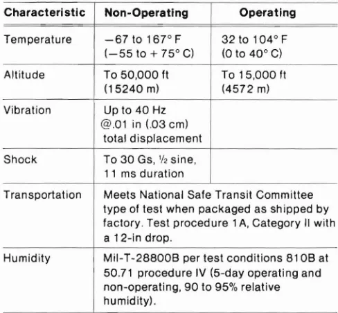
Physical Characteristics A-1
Power Requirements A-1
Environmental Specifications A-1
Performance Specifications A-2
Page Sizes A-3
Nonfatal Error Types C-1
GENERAL INFORMATION
ABOUT THIS MANUAL
This manual provides general information and operat-ing instructions for the TEKTRONIX 4663 and 4663S Interactive Digital Plotters.
NOTE
The 4663S Interactive Digital Plotter provides the following standard features (optional with the
4663):
• GPIB Interface
• Circular interpola tion and programmable macros
• Downloadable characters and math character set
• Added parameters storage
The first three features are described in the 4663 Interactive Plotter Programmer's Reference
Manual, while adescription of the added
parame-ters storage is found under "Parameter Setup Select Line" (Parameter Entry Module) in Section 3 of this manual.
Section 1, General Information, introduces the major features of the Plotter and lists the available options and accessories.
Section 2, Getting Started, presents five topics de-signed to guide the operator through the series of operations required to prepare the Plotter for plotting. Much of the information in this section is tutorial; you will be told exactly what to do to perform a given task.
The last major topic in this section, Using the Front
Panel Controls, provides step-by-step instructions for many of the jobs the operator can perform. It may be helpful for the first-time operator to perform each operation as a training exercise.
Section 3, Controls and Indicators, includes detailed information about the function of the Plotter's front panel switches and indicators. This section provides additional technical information not included in Section 2.
Section 4, Pens and Media, describes all aspects of the Plotter pens and media, including pen types, media types, instructions for loading media, pen installation, selection, and pen maintenance.
Section 5, Maintenance, includes instrument cleaning instructions and adjustments the operator can perform.
RELATED DOCUMENTATION
In addition to this Operator's Manual, the following manuals support the TEKTRONIX 4663 Interactive Digital Plotter:
• 4663 Interactive Digital Plotter Programmer's
Refer-ence Manual
• 4663 Interactive Digital Plotter Reference Guide
• 4663 Interactive Digital Plotter Service Manual (two
MAJOR FEATURES OF THE 4663 INTERACTIVE DIGITAL PLOTTER
The 4663 is a C-size (metric size A2) flatbed interac-tive digital plotter. It can handle up to 17x22 inch (432x569 mm) sheet media and, with the Media Advance option, 18-inch wide roll media. The 4663 Plotter can plot on paper or film with fiber-tip, plastic hard-tip, or wet-ink pens.
Compatibility exists in nearly all environments. RS-232-C full duplex comes standard; a GPIB interface is optional. The 4663 supports TEKTRONIX PLOT 10 and PLOT 50 Graphic Software.
The 4663 produces all 94 printable ASCII characters. Characters can be scaled, slanted, rotated, and cen-tered. Ten character fonts come standard with the 4663 and others are offered as options.
The 4663 also includes a Positioning Control (Joystick) for digitizing operations, pen carriage positioning, and media advancement (the latter requires the Media Advance option). A crosshair CL.rsor is located on the pen carriage.
AParameter Entry Card allows easy selection of
operating parameters. This feature allows the user to select parameters such as baud rate, pen type, pen pressure, pen velocity limit, aspect ratio, Page size, and others. The Plotter includes a battery so these
parameters can be stored up to approximately 90 days (45 days with Option 37 installed) without power. Option 37 allows three additional parameter sets to be stored and retrieved so that up to four users can configure the Plotter to their individual requirements by pressing a single retrieval switch.
OPTIONS TO THE 4663 PLOTTER
The following describes the options available for the 4663 Interactive Digital Plotter.
Option 01 GPIB Interface - provides communications
with GPIB instruments, such as the TEKTRONIX 4050 Series Controllers, while maintaining the standard RS-232-C interface capability.
Option 04 GPIB Interface Only - replaces the standard
RS-232-C interface with a GPIB interface to permit communications with GPIB instruments. Option 04 cannot be configured with Options 01 or 30.
Option 30 RS232C Interface to TEKTRONIX 4081
-permits the Plotter to communicate with the TEKTRON-IX 4081 Graphic System.
Option31 Circular Interpolation and Programmable
Macros - permits the Plotter to draw arcs and circles
and to save and then recall macros (series of MOVEs,
DRAWs, PRINTs, or other Plotter commands).
Option 32 Downloadable Characters and Math Character Set - provides Greek and math character
sets, and allows a user to add, modify, or define characters or sets of characters.
Option 36 Media Advance - permits the Plotter to be
equipped with roll media in addition to the standard sheet media. With roll media installed and activated on the Parameter Entry Card, program control of the media advance allows mUltiple plots to be produced without requiring operator intervention.
Option 37 Added Parameters Storage - allows three
additional sets of Parameter Entry Card setups to be saved and later recalled. With this option installed, up to four users can configure the Plotter to their individu-al requirements by pressing a single switch.
Option 48 220 Volt Operation - operates the 4663
STANDARD ACCESSORIES
The following accessories are shipped with the 4663 Plotter.
Power Cord
RS-232-C 15 ft. cable (standard with basic unit only)
GPIB ifF Cable, 6.5 ft. (2 meter) (standard with Options 01 and 04)
161-0066-00
012-0829-00
01 2-0630-03
Pen - fiber tip, pkg. of 3 Black
Red Blue Green
Paper - sheet, blank, white,
432x559 mm (17x22 in), box of 100 sheets 016-0414-00 016-0415-00 016-041 6-00 016-0417 -00 006-31 50-00
4663 Interactive Digital Plotter Op-erator's Manual
4663 Interactive Digital Plotter Pro-grammer's Manual
070-3807 -00
070-3806-00
Paper - roll, blank, 18 in x 200 ft (standard with Option 36 only), 2 rolls/box
Computer Graphics Supplies Catalog
006-2837-00
11AX-4761
4663 Interactive Digital Plotter Ref-erence Guide
070-2828-01
OPTIONAL ACCESSORIES
These accessories can be ordered from Tektronix, Inc..
NOTE
Pens listed for use on the 4663 Plotter can also be used on 4662 Option 31 Plotters.
4663 Interactive Digital Plotter Ser-vice Manual Vol. I
070-2669-00
Transparency Kit
Dust Cover - soft vinyl
Pens - fiber tip for paper, pkg. of nine pens, all colors included
Pens - fiber tip for film (water soluble), pkg. of nine pens, all col-ors included 020-0595-00 200-2392-00 016-0687 -00 016-0688-00 (cont) 016-0682-00 016-0683-00 016-0684-00 016-0685-00 01 6-0686-00 016-0414-00 016-0415-00 016-0416-00 016-0417-00 Pens - fiber tip for paper, pkg. of 3
Brown Orange Yellow Purple Magenta Black Red Blue Green 006-2836-00 070-3453-00 006-3473-00 006-2837 -00 Media
Paper - sheet, blank, Vellum 432x559 mm (17x22 in), 100 sheetslbox
Roll Paper - blank, 457 mm x 61 meters (18 in x 200tt), 2 rolls/box, C-size after tear off
Roll Paper - blank, 457 mm x 61 meters (18 in x 290 ftl, 2 rolls/box, metric size A2 after tear off
Film - Antistat, Polyester, 432x559 006-2835-00 4663 Interactive Digital Plotter
OPTIONAL ACCESSORIES (cont)
Pens - fiber tip for film (permanent), pkg. of 3
Black Brown Red Orange Yellow Green Blue Magenta Purple
Pens - hard tip for paper, pkg. of 3 Black
Red Green Blue
Wet-Ink Pen Assembly
Point size PL3 - (.01 ",0.3 mm dia.) Point size PL5 - (.02",0.5 mm dia.) Point size PL8 - (.03",0.8 mm dia.)
Replacement Tips
Wet-Ink Tip - PL3 - (.01 ",0.3 mm dia.)
Wet-Ink Tip - PL5 - (.02",0.5 mm dia.)
Wet-Ink Tip - PL8 - (.03", 0.8 mm dia.) 016-0418-00 016-0418-01 016-0418-02 016-0418-03 016-0418-04 01 6-0418-05 016-0418-06 016-0418-07 016-0418-08 016-0668-00 016-0668-01 016-0668-02 016-0668-03 016-0444-01 016-0442-01 016-0443-01 214-2706-00 214-2706-01 214-2706-02
Pen Replacement Part Kit, contains: 1 cap, 1 body section, 2 plain nuts, and 6 ink cartridges
Extra Ink Cartridges (1 ea.)
Ink - for wet-ink pens, 3/4 ounce, squeeze bottle For paper: Black Forfilm: Black Red Blue Green Brown
Solvent, Ethyl Alcohol (4 oz)
Cleaning and Maintenance Systems Cleaning Tank, Ultrasonic (1 ea) Cleaning Fluid, 3069 Ultrasonic (8 oz)
Cleaning Fluid, 3068 with Strainer (5.2 oz)
Pressure/Suction Cleaning Bulb (1 ea)
Magnifying Instrument, 3095 PMG (1 ea)
Humidifier, Pen Storage 746-700 (1 ea) 006-2968-01 016-0649-00 016-0428-00 016-0427-00 016-0426-00 016-0425-00 016-0424-00 016-0423-00 006-3380-00 002-1555-00 002-1556-00 002-0920-01 002-1 560-00 002-1 558-00 002-1559-00
For a complete listing and description of all Tektronix Plotter supplies, please request a copy of the current
Computer Graphics Supplies Catalogfrom the nearest
GETTING STARTED
This section provides the information needed to pre-pare the Plotter and the operator to begin plotting as soon as possible. The following topics are covered:
• Introduction to the Plotter - provides a quick orientation to the Plotter's controls, indicators, and basic terminology.
• Operator's Installation Check - allows the operator
to easily verify that the Plotter is correctly installed. It includes references to detailed information locat-ed in other parts of this manual or in the 4663
Service Manual.
• Using the Parameter Entry Card - describes the
selections to make on the Parameter Entry Card for general plotting. Selections are indicated for both Serial and GPIB interface applications .
• Installing Pens and Media.
• Run Self- Test - verifies that the Plotter's electrical and mechanical components are functioning proper-ly.
• Using the Front Panel Controls - gives step-by-step
INTRODUCTION TO THE PLOTTER
Figure 2-1 and the following text provide a quick overview of the Plotter's controls and indicators. Additional information about the controls and indica-tors is included in Section 3.
~
Before turning the POWER switch on, make sure the Plotterisclear of all materials. The pen carriage moves to the upper-right corner5to 10 seconds after powerisapplied.
• POWER switch - The Power switch is used to turr: the Plotter on and off.
• Control Matrix - The cluster of switches at the center of the front panel used to control many of the Plotter functions. The Control Matrix includes two SHIFT switches, two INTERFACE switches, six FUNCTION switches, and the indicators within these switches.
• SHIFT 1 and SHIFT 2 - These two switches are used to select one of the available functions of a FUNCTION switch. SHIFT 1 is the lower switch; SHIFT 2 is the upper switch.
• INTERFACE switches - These two switches are used to establish the correct interface hardware configuration to allow communications with the other system devices.
• FUNCTION switches - These six switches, used in conjunction with the SHIFT switches, allow selection of a variety of Plotter operations.
• Switch names - The top row of labels indicate the names of the switches. The other rows of labels indicate the operations performed by the switches.
• Pen Control switches - This group of switches is used to select the active pen, to adjust the pen pressure on the media, and to manually raise or lower the active pen.
• Positioning Control (Joystick) - The Joystick con-trols the position of the pen carriage, advances the media if the Media Advance Option is installed, and is used during digitizing operations.
• Parameter Entry Module - The Parameter Entry Module includes the INIT light, lighted switches, and the Parameter Entry Card.
• Parameter Entry Card - The Parameter Entry Card serves as a directory of the Plotter's operating parameters.
• Lighted switches - The switches on the Parameter Entry Module select the desired parameters; the lights indicate the active selections.
• INIT light - This light, on the Parameter Entry Module, signals the operator to fully insert the Parameter Entry Card before examining or changing parameter selections.
• Pen carriage - The pen carriage carries the pens about the plotting area.
• Pen holders - The two pen holders accept a variety of pen types and colors. The holder nearer the front panel holds PEN 1; the other holds PEN 2.
• Crosshair cursor - This small plastic crosshair device, mounted on the pen carriage, indicates the position to which the active pen will move when itis directed to draw on the media.
~
IIIIII:
UGHTED SWITCHESINIT LIGHT ",PARAMETER
ENTRY
CARD PARAMETER
ENTRY
MODULE
3807-1
OPERATOR'S INSTALLATION CHECK
This Operator's Installation Check provides the infor-mation necessary to quickly verify that the Plotter is properly installed and ready to make plots. These procedures may be helpful in other circumstances, such as:
• When training a new operator.
• When relocating the Plotter, to check that the cables are correctly reinstalled.
• If plotting problems occur, to check that the Plotter is properly installed before calling a service person.
~
This procedureis a CHECK only. The initial installation of the Plotter must be performed by qualified service personnel only, in accordance with the installation instructions located in the
4663 Service Manual, Volume 2, AppendixA.
PROCEDURE
1. Check the location. The Plotter should be placed on a solid, level desk or table that is at least 38x30 inches (97x77 em) in size. Make sure that no materials are on the plater.
2. Check that the POWER switch is off and the power cord is attached to the voltage source.
3. Check that the interface cables are installed correctly for your application. Refer to Figure2-2
while reading the following:
• For Serial interface applications, check that the cable from the terminal is connected to the Plotter connector labeled TERMINAL. If a host computer is to be used, attach the cable from a modem (or computer) to the Plotter connector labeled MODEM .
• For GPIB interface applications, attach the cable from the controller to the Plotter connector labeled IEEE-488-1975.
~
Before turning the POWER switch on, ensure that the platen (plotting surface) isclear of all materi-als. The pen carriage moves to the upper-right corner of the platen when powerisapplied.
4.
Turn the POWER switch on. After a brief period (5-10 sec), the pen carriage moves to the platen's upper-right corner.NOTE
Ifthe Plotter's bell sounds during the power-up sequence and the Error Reset light on the front panelisnot flashing, the Parameter Entry Card selections are not correct. Correct selections must be made on the Parameter Setup Select line and the Interface Select line of the Parameter Entry Card before the Plotter can be used. See
Using the Parameter Entry Card next in this
section for instructions.
5. Check the INTERFACE switches. For most applica-tions, both Interface lights should be turned on
- . . - - I _
-
~~,3807·2
USING THE PARAMETER ENTRY CARD
The Parameter Entry Card permits the operator to enter, observe, and modify the Plotter's parameters. Using the available selections, the Plotter can be set to operate with different controllers and host computers, can use a variety of pens and media, and can tailor the plotting Page and Viewport to meet special require-ments. For detailed information about any line on the Parameter Entry Card, refer to Section 3 of this manual.
Checking and resetting the selections on the Parame-ter Entry Card lines is easy. With the POWER switch on:
1. Push the Parameter Entry Card in fully, making sure the INIT light turns off.
2. Check the current selections by pulling the Param-eter Entry card out slowly, stopping at each line. One or more of the lighted switches may be on, indicating the current parameter(s) for that line.
3. Change the current setting (if necessary) by pressing the switch above the desired parameter (the light should turn on). On lines that permit only one selection at a time, the light above the
previously selected parameter will turn off. On some lines, multiple selections are possible so more than one light may be on.If an invalid selection is made, the Plotter's bell sounds once and the switch does not light.
4. Push in the Parameter Entry Card when all lines are checked or reset.
The selections are remembered for approximately 90 days (45 days if Option 37 is installed), even if power is removed from the Plotter.
Figure 2-3 lists the Parameter Entry Card settings suitable for general plotting and can be used to record the Parameter Entry Card settings for your specific applications. Space is provided to record the
application of each setup, as well as other information such as the type and color of pens used, the media used, and so forth. Figure 2-3 also includes:
• Two sample setups, one for Serial and one for GPIB installations. These setups list settings suitable for general plotting, and should be very useful when the Plotter is first installed, Using the settings listed, you can quickly set up the Plotter and begin plotting.
• Four blank columns, labeled Setup 1 through Setup 4, correspond to selections available on the Parame-ter Setup Select line of the ParameParame-ter Entry Card. (Option 37, Added Parameters Storage, must be installed to use all four selections; only SETUP 1 can be selected on standard instruments.) Use these columns to record the line settings for your specific applications. These columns should be filled in (with pencil) during installation of the Plotter. This provides a handy reference for other Plotter users.
On those instruments with Option 37 installed, you can program the Plotter to remember up to four complete sets of parameters. For more information, refer to the description of the Parameter Setup Select line of the Parameter Entry Card, located in Section 3.
To set the Parameter Entry Card for general plotting, locate the two columns in Figure 2-3 labeled Sample
Setups.Choose either the Serial or GPIB, depending on
your installation, and make the selection indicated for each line.
NOTE
When the selection is changed on either the Parameter Setup Selectorthe Interface Select lines of the Parameter Entry Card, the Plotter reinitializes. The Parameter Entry Card must then
be pushed fully in before examiningormodifying
SETUP 1 APPLICATION:
SETUP 2 APPLICATION:
SETUP 3 APPLICATION:
SETUP 4 APPLICATION:
NOTES:
SAMPLE SETUPS RECORD YOUR SETUPS HERE LINE NAME
SERIAL GPIB 1 2 3 4
EXECUHSUfTUT 1 2 3 4 I 5 5 I 7 B - -
-(RlOIMlA. fRAOR IKAOI I 2 3 ....: .. I
•
I•
--
-COD' COUI' ElIliOft ,
DUTM tllMIUTQII
••
CI , laT 101( CR-•nom.CIAUCTU
...
J A.'"
ESC-untIfACE fUlenol, MIInAUTD ell ItltlAlULf IGNORfDEl ~... AUTO MUTE
-DC1JDC3 COIfIIOl
-,
DIITPlIT I --
-.
~f··u"tAnou FUll IWtDWAIU RlClIVI FULL --OIlTlOlltOD£ DUPlD fLAGlliIl" DUPLEX
'leWE 'AIm DDD MI IUDRl "IOR( IGNORE
fIAnIIlT,AJUTY DDD
,
...
LOBICO lOlle 1 LOGIC 0CltAllACTfIFOIUllAT 7 8 '..D.11112 Band 1
nwlSMIT lAUD 5D 7. 110 300 .DO 1200 S~~'tD FUll -
-unLIlli' SPEED
00 70 134.5 100 1800 IXfXT llX Ell lex ar -
-TUIIIIII1 lAUD RATE 110 300 .00 1200 2.00 ••00 9800 ~ -
-.0 70 134 .• '"0 laoo lX EXT tlX EXT I4X liT -
-litEm lAUD UTI 110 300 100 1200 2400 4800 9800 ~ -
-SHIM nEYlCE ADDRESS A 8 C D
•
F G H A (E) --INTERFACE FUNCTIONS CR GENERATES IF - - CR/LF
INTERfACE MODE NORMAL LtSHNONLY ONLYTAU - - NORMAL
GPI8 DEVICE ADDRESS 1 2 3 4 5 6 7 B - - (D)
=~liE fORMATCD.MAJlD; 1 2 3
•
•
0 7•
1 1 (C)INHRFACE SHECT 1 2 1 (G) g~i:&L3(G
:t~HAIAC1'", .D••AlI...DI I I I
•
NORMAL NORMALPfN~HOCITYliMIT 6 IPS I B IPS I TOIP~Ec~a~2IPS 14 IPS I 16 IPS
FU'ixfflEEO - -
-
-PEN PRESSURE 5GM 10GM 15 GM 20 GM 25 GM 30 GM 35 GM 40 GM - - --PEN TYPE FIBER WIT PLASTIC FIBER TIP FIBER TIP
TIP
'N,
HARD TIP-1 (B) 2(B~ 1 (B) 2 (B
PEN PARAMETER ACCUS PEN 1 PEN 2
Ulf GUAUTY ...IW NORMAl T•••• 2
•
NORMAL NORMAL...
INITIAL AXIS 'c=J, ,c::J' 'c::::J, ,c:::J' 'c:::J, ,r=:Jx 'c::::J, ,c:J' 'c=J, 'c=J,
ORIENTATION
INIHAL ASPECT RATIO PAGEfULL 3X:2Y 4X·3Y lX.1Y 3X:4Y 2X:3Y FULL PAGE FULL PAGE PAGE ORIENTATiON HORIZONTAL VERTiCAL HORIZONTAL HORIZONTA INITIAL PAGE fORMAT DRAFTING GRAPHING DRAFTING DRAFTING INITIAL PAGE SIZE C ENGliSHB A A2 METRICA3 A4 RECALLUSER DEfiNEDSA~E C C
MEDIA fORM SHEfT ROLL SHEET (A) SHEET (A)
...
SETUP 1 SETUP 1'..
.
. . . . .
,.
NOTE: A Select ROLL if Media Advance Option installed (optional).
B Select PEN 1, then select FIBER TIP on next line. Select PEN 2 and repeat. C Select 1 for use with TEKTRONIX, INC. 4050 Series Graphic Computing Systems.
INSTALLING MEDIA AND PENS
Pens and media (paper, film, etc.) must be installed before running the self-test and using the front panel controls. The instructions included here are abbreviat-ed and are only for loading sheet mabbreviat-edia. They are designed to help you begin plotting quickly; for addi-tional information, including instructions for the installation of roll media, refer to Section 4, Pens and
Media.
While performing the procedures in this section, use C-size sheets of blank, white paper and install fiber-tip pens. If you made the selections indicated in the earlier discussion of the Parameter Entry Card, the parame· ters are already set correctly for these pens and media
LOADING SHEET MEDIA
NOTE
The Media Form line on the Parameter Entry Card must be set to SHEET.
Install sheet media according to the following instruc-tions:
1. Pressthe POWER switch off, then back on. After 5
to 10 seconds, the Plotter moves the pen carriage to the upper-right corner.
The Media light should be blinking, indicating that the electrostatic hold-down is turned off to allow removal or installation of the media.
2. Placethe C-size sheet of media on the platen,
aligning it with the arrow in the lower-right corner of the media guide. Align the bottom edge of the media evenly along the mecia guide. See Figure
3. Pressthe MEDIA switch to activate the electrostat-ic hold-down.
4. Removeany bubbles from the media using a clean, lint-free industrial wipe or a drafting brush. Avoid using your hand as body oils will be transferred to the paper, which reduces the acceptance of ink.
This completes the sheet-media loading instructions.
PEN INSTALLATION
~
To protect the platen from ink spills or other damage, always place media on the platen before installing pens. To prevent damage to the pen tips and to prevent fiber-tip pens from prematurely drying out, always replace caps on pens that are not in use.
Before installing any pen, use that pen to write on a piece of scrap media to ensure that ink flows. Be careful not to press too hard, since excessive pressure could damage the pen tip. Then simply screw the pen into the pen holder, as shown in Figure 2-5.
RUN SELF-TEST
You can perform a brief operational test of the Plotter using the following procedure. This test verifies the operation of only one pen; the second pen must be selected and the test run again to perform an
operational test of both pens. This test does not verify communications with a controller or a host computer.
,
~
Pens and media must be installed before operat-ing the Self- Test. SeeInstalling Pens and Media
earlier in this section.
1. Turnthe POWER switch off, then back on. After 5 to 10 seconds, the pen carriage will move to the upper-right corner. Make certain that paper and pens are installed, then press the MEDIA switch.
2. Checkthat the INIT light (located on the left side of Parameter Entry Module) is off. If the light is on, push the Parameter Entry Card in all the way. The light should go out.
3. Movethe Joystick handle around. The pen car-riage should move in the same direction you move the handle.
4. Operatethe Self-Test features, as follows.
NOTE
The appearance of the test pattern can be changed if any of the following Parameter Entry Card lines have other than the left-most switch selected: Media Form, Initial Page Size, Initial Page Format, Page Orientation, Initial Aspect Ratio, and Initial Axis Orientation.
If you set the parametersas directed in Using the Parameter Entry Card, earlier in this section, the
Parameter Entry Cardisset correctly and the plot will appearas shown in Figure 2-6.
a. Pull out the Parameter Entry Card to the last line (Execute Self Test).
b. Pressthe switch above 2. All front panel switch lights and all Parameter Entry Module lights should turn on. PRESS this switch again to cancel the light test.
NOTE
If any front panel lights are flashing, the front panel lights will light only temporarily during this test.
NOTE
In the next step, the Plotter will draw
a
test pattern. During this test, the Plotter drawsa
box with two dashed lines extending diagonally from corner to corner and intersecting at the center of the box (see Figure2-6). The Plotter then drawsa
fan pattern in the lower-left corner of the Page. Next, the message "Please exercise the Joystick"isprinted. At this time, use the Joystick to reposition the pen carriage. After
a
short period, the Plotter resumes plotting and redraws the intersection of the dashed diagonal lines within the box. This demonstrates the Plotter's ability to repeatedly draw vectors at the same location on the media, even if the Joystick has repositioned the pen carriage.c. Pressthe switch above 1 to draw the plot shown in Figure 2-6.
If these tests are successful, the Plotter is operational. If the resultant plot is different from that shown in Figure 2-6, check these selections on the following Parameter Entry Card lines: Media Form, Initial Page Size, Initial Page Format, Page Orientation, Initial Aspect Ratio, and Initial Access Orientation. If any of these lines have other than the left-most switch
Please exercise the joystick:
Plot ends here after Joystick use. One half of the Intersection Is drswn early In the plot, while the remainder of the Intersection Is drawn at the end to verify repeatability.
Figure 2-6. Test Pattern Drawn by Self-Test Feature.
/
/
/
/'
USING THE FRONT PANEL CONTROLS
This series of instructions describes the steps required to perform Plotter operations that use the front panel controls. A more detailed description of the front panel controls is included in Section 3. Controls and
Indica-tors.The first-time operator may want to perform each of the operations in sequence to learn the operation procedures as quickly as possible. The experienced operator, who may occasionally need to refresh his or her memory, can refer to the Front Panel Operations Index that follows to locate the operating procedure for anyone front panel. Figure 2-7 illustrates the front panel switches.
OPERATOR'S CHECK PROCEDURE
The first step of this procedure serves as an Operator's Check Procedure. Perform this step to verify that each of the Plotter's functions, indicators, and switches is operational. The remaining procedures (Steps 2 through 16) will familiarize the operator with other front panel operations.
INTERFACE SWITCHES
A
Whenever a SHIFT and a FUNCTION switch are used jointly to select a function, the SHIFT switch must be pressed before pressing the FUNCTION switch.
Illustrations that accompany some of the following steps can be used to help locate the switches required to perform the operation under discussion.
The terms Page and Viewport are described at length in the Introduction Section of the 4663 Programmer's
Reference Manual. Default Page and Viewport
dimen-sions are described in Appendix A of this manual. Brief definitions are as follows:
• The Page corresponds to the size of the media being used, minus the margin areas.
• The Viewport is the area of the Page on which the plot is drawn. The Viewport can occupy all or part of the Page.
FUNCTION SWITCHES
FRONT PANEL OPERA1"IONS INDEX
Media and pens must be installed before com-pleting the following procedures. See Installing Media and Pens earlier in this section for instruc-tions. Procedure Step No. 1 2 3 4 5 6 7 8 9 10 11 12 13 14 15 16 Title Check Procedure
Lower a Pen to the Paper and Exercise the Joystick
Change the Pen Selection
Locate the Upper-Right Corner of the Page
Locate the Upper-Right Corner of the Viewport
Select the Mark Viewport Function Select the Outline Viewport Function Select a Different Page Size
Select a New Page Orientation Change the Parameter Entry Card Set a New Viewport
Change the Paper in Sheet Mode
Change the Paper in Roll Mode (Requires Option 36)
Reposition the Page Define a Page Size
Make Mirror-Image or Upside-Down Plots
NOTE
b. Check the INIT light. If it remains on, push the Parameter Entry Card in fully to complete initialization.
c. Check or set the following Parameter Entry Card lines: Initial Page Size set to C, Page Orientation set to HORIZONTAL, and Initial Aspect Ratio set to 3X:2Y.
d. Move the Joystick down and to the left to move the pen carriage to the center of the platen. Notice that the pen carriage moves in the same direction as you move the Joystick and that the pen carriage velocity increases as the Joystick deflection angle increases.
e. Check that the SELECT 1 light is on (one of the Pen Control switches). If not, press the SELECT 1 switch.
2. Lower a Pen to the Paper and Exercise
the Joystick
a. Press the UP/DOWN switch. The pen carriage moves the selected pen into position and then lowers the pen to the paper.
b. Move the Joystick around, drawing a line on the paper.
c. Press the UP/DOWN switch again. The pen is raised and the pen carriage automatically positions the intersect point of the crosshair cursor above the last pen position.
1.
Check Procedure
~
BEFORE turning the POWER switch on, ensure that the platen is clear of all materials. The pen carriage moves to the upper-right corner of the platen soon after power is applied.
a. Press the POWER switch on. After 5 to 10 seconds, the pen carriage moves to the upper-right corner of the platen (the load point). If the MEDIA switch light is flashing, PRESS the MEDIA switCh.
3.
Change the Pen Selection
a. Press the SELECT 2 switch on the Pen Control.
b. Press the UP/DOWN switch. Notice that Pen 2 now moves to the point previously occupied by the crosshair cursor.
4. Locate the Upper-Right Corner of the
Page
a. Press, then immediately release, the UPPER RIGHT switch. The crosshair cursor moves to the upper-right corner of the current Page.
5. Locate the Upper-Right Corner of the
Viewport
a. Press the UPPER RIGHT switch and hold L.ntil the betl rings (approximately 2 seconds). The pen carriage moves immediately to the upper-right corner of the Page when the bell rings.
b. Release the UPPER RIGHT switch. The pen carriage will move to the upper-right corner of the current Viewport.
NOTE
The Lower Left Locate functions are operated in the same manner as the Upper Right Locate functions.
NOTE
When the Initial Aspect Ratio line on the Parameter Entry Card is set to FULL PAGE, the Page and Viewport boundaries are the same.
6. Select the Mark Viewport Function
a. Press the upper SHIFT switch (SHIFT 2). b. Press the PLOT CONTROL switch. The Plotter draws small 900
angle brackets at each corner of the Viewport. The pen carriage then returns to the last active pen position.
7. Select the Outline Viewport Function
a. Press the lower SHIFT switch (SHIFT 1). b. Press the PLOT CONTROL switch.
8. Select a Different Page Size
a. Pullthe Parameter Entry Card out to the third line (Initial Page Size) and press the switch above A.
The light above A turns on and the light above C turns off. The Plotter is now programmed for an A-size Page and Initial Viewport as deter-mined by the Initial Aspect Ratio of 3X:2Y. The previous Page and Viewport (which you set earlier) are lost.
b. Outlinethe Viewport as you did in Steps 10 and 11 by pressing SHIFT 1, then the PLOT CONTROL switch. This draws the boundaries of the new Viewport.
9. Select a New Page Orientation
a. Pullthe Parameter Entry Card out to the fifth line (Page Orientation).
b. Pressone of the two switches above VERTI-CAL. The pressed switch will light and the light above HORIZONTAL will turn off. The Page is now oriented vertically on the paper and the margins are the correct size.
c. PressSHIFT 1, then press the PLOT CON-TROL switch to outline the new Page (and Viewport) orientation. The Page has been rotated around the lower-right corner of the original Page. The X- and Y-axes of the Viewport have also rotated with the Page. This can be verified using the Locate Lower Left functions described earlier.
10. Change the Parameter Entry Card
To return the Plotter to the configuration used at the start of this procedure, change the Parameter Entry Card settings as follows:
a. Changethe Page Orientation li'18 to HORI-ZONTAL.
b. Changethe Initial Page Size iine to size C.
11 . Set a New Viewport
a. Movethe pen carriage using the Joystick to a point well within the last marked Viewport.
b. Pressthe upper SHIFT switch followed by the LOWER LEFT switch to activate the Set Viewport Lower Left function.
c. Movethe pen carriage in a45°angle up and to the right about 3 to 6 inches (7 to 15 em). This point must also be within the last marked Viewport.
d. Pressthe upper SHIFT switch again.
e. Pressthe UPPER RIGHT switch to set the upper-right corner of the Viewport.
12. Change the Paper in Sheet Mode
NOTE
Steps 12 and 13 provide directions for changing
paper. If in SHEET mode (as established on the Parameter Entry Card), perform Step 12.If in
ROLL mode, go to Step 13 for paper changing
instructions. Refer to the Section 4, Pens and Media, for additional information. The term
"pa-per," rather than "media,"isused here since paper should be installed at this time.
a. Pressthe MEDIA switch. The electrostatic hold-down turns off, the pen carriage moves to the load point (upper-right corner of the the platen), and the Media light flashes.
b. Replacethe paper with a clean sheet of C-size paper.
c. Pressthe MEDIA switch. Use a drafting brush or an industrial wipe to smooth out any wrinkles in the paper; avoid using your hands as body oils will transfer to the paper and reduce the paper's ability to accept ink.
13. Change the Paper in Roll Mode
(Requires Option 36)
a. Pressthe MEDIA switch. The pen carriage moves to the load point (upper-right corner) and the paper automatically advances.
14. Reposition the Page
The Page can be repositioned by setting the lower-left corner of the Page. To reposition the Page:
a. Movethe cross hair cursor, using the Joystick, to the desired position of the lower-left corner of the Page.
b. Press the SHIFT 1 switch. c. Pressthe LOWER LEFT switch.
This completes the procedure for repositioning the Page. As shown in Figure 2-8, notice that moving the lower-left (LL) corner also moves the upper-right (UR) corner. This maintains the same Page size. The newly positioned Page corner boundaries can be verified by first momentarily pressing the LOWER LEFT switch and then pressing the UPPER RIGHT switch. The crosshair cursor travels to the respective corners of the Page.
UR (old)
PAGE
LL
(old)
A.
scaled
Page prior to reposftlonlng.UR (new)
"-
...,
"'-' r - -
- - - - ,"'-I
I
LL
I
I
(new) , I
"
I
,
I
"
I
"'-L _____
~B.
Page RepoeItIoned ~.a Figure 2-8. Page Positioning.15. Define a Page Size
a. Move the crosshair cursor, using the Joystick, to the desired position of the lower-left corner of the page. (If the lower-left corner is to remain the same, skip ahead to Step d.)
b. Press the SHIFT 1 switch.
c. Press the LOWER LEFT switch.
d. Move the crosshair cursor, using the Joystick, to the desired position of the upper-right corner of the page.
e. Press the SHIFT 1 switch.
f. Press the UPPER RIGHT switch.
16. Make Mirror-Image or Upside-Down
Plots
The Plotter can be set to orient the plotting area to produce mirror, down mirror, or upside-down image plots. The right column of Figure 2-9 shows an example of each of these features. Compare the placement of the lower-left (LL) and upper-right (UR) corners in the three plots to the standard plots (left column). These features can be useful in preparing plots for mirror or projection transparencies.
Mirror Image Plots (Figure 2-9a):
a. Position the pen, using the Joystick, at the lower-right corner of the Page.
b. Press SHIFT 1 and then the LOWER LEFT switch.
c. Position the pen, using the Joystick, at the upper-left corner of the Page.
d. Press SHIFT 1 and then the UPPER RIGHT switch.
Upside-Down Mirror Image Plots (Figure 2-9b):
a. Position the pen, using the Joystick, at the upper-left corner of the Page.
b. Press SHIFT 1 and then the LOWER LEFT switch.
c. Position the pen, using the Joystick, at the lower-right corner of the Page.
d. Press SHIFT 1 and then the UPPER RIGHT switch.
Upside-Down Image Plots (Figure 2-9c):
a. Position the pen, using the Joystick, at the upper-right corner of the Page.
b. Press SHIFT 1 and then the LOWER LEFT switch.
c. Position the pen, using the Joystick, at the lower-left corner of the Page.
·>b,)eyol &rlJ $ai~:n9)(9 920sfCj
UR /
"
>~
/
/
"
Please exercIse the JOYSllCk
LL LL
A.
STANDARD PLOT MIRROR IMAGEUR LL
:<
"
/
"
Please exercise the joyslickbl602G6X6LC!26 fI.J6 ~oAZr!ct<:
"
/:<
/"
LL / UR
B.
STANDARD PLOT UPSIDE.oOWN MIRROR IMAGE"
"
UR/ LL<
/
"
/"
Please exercise the joyslick:
:>j::l!ls,l,0f Ol.!1 as!::l.Jaxit aso91d
CONTROLS AND INDICATORS
INTRODUCTION
This section includes detailed information about the function of the Plotter's front panel switches and indicators. The front panel is illustrated in Figure 3-1 and includes the following:
• The Power Switch
• The Positioning Control (Joystick)
• The Pen Controls
• The Control Matrix
• The Parameter Entry Module
Detailed information about the operation of these switches to perform specific tasks is included in appropriate sections throughout this manual.
POWER SWITCH CONTROL MATRIX
~ r~----~A~
-PAIWIETERENrRY
IIODUU!
Figure 3-1. Front Panel Controls and Indicators.
POWER SWITCH
The POWER switch is a rocker switch used to activate the Plotter. (Some circuits always have power applied
when the Plotter is plugged in. These are described in the 4663 Service Manual.)
POSITIONING CONTROL (JOYSTICK)
The POSITIONING CONTROL (or Joystick) is used to move the pen carriage manually about the platen. If the Media Advance Option (Option 36) is present, the Joystick can be used to position roll media on the platen. Information about this second function is locat-ed in the description of the Manual Motion function, later in this section.
The Joystick is enabled either at power-up or approxi-matelya half-second after the pen carriage stops moving in response to Plotter commands. One or both axes of the Joystick can be disabled by the JOYSTICK
DISABLE command, described in the 4663
Program-mer's Manual.
To move the pen carriage, simply push the Joystick in the desired direction. Notice that the velocity of the pen carriage increases as the angle of deflection increases.
When using the Joystick, remember that if neither pen is down, the crosshair cursor on the pen carriage indicates the position at which plotting will occur when the selected pen is lowered.
~
Do not use the Joystick to move the pen carriage under any of these conditions:
• During the 5to 10 second power-up sequence.
• When changing selections on either the Parameter Setup Select line or the Interface Select line of the Parameter Entry Card.
• When using the front panel Initialize function.
• When using
a
front panel Media switch function.Failure to observe this precaution can cause loss of the pen carriage position and you will hear
a
grinding noise. A front panel Initialize function (discussed later in this section) is used to recover from this condition.PEN CONTROLS
The Pen Controls include these three controls:
• SELECT switches (1 and 2) and their light indica-tors.
• UP/DOWN switch and its light indicator.
• PRESSURE OVERRIDE control.
Two switches, labeled SELECT 1 and SELECT 2, can be used to manually select the active pen (the PEN SELECT command is also used to designate the active pen). Lights within the switches indicate the selected pen. SELECT 1 selects the pen closest to the front panel; SELECT 2 selects the remaining pen.
Pressing the UP/DOWN switch alternately lowers or
The two PRESSURE OVERRIDE adjustments can be used to make fine adjustments to the pressure of the pens on the media. This feature can be used to improve line quality and to minimize pen tip wear, The left control affects Pen 1 and the right control affects Pen 2.
The nominal pen pressure is set automatically accord-ing to selections made on the Parameter Entry Card (see Pen Group in the Parameter Entry Card descrip-tions). Moving the PRESSURE OVERRIDE control toward
"+ ..
increases the pen pressure; moving the control toward "-" decreases pressure. The full range of this control varies the pen pressure approximatelyCONTROL MATRIX
The Control Matrix includes switches and lights. The switches select a variety of Plotter functions and the lights (located within the switches) indicate the operat-ing conditions.
The Control Matrix includes three sets of switches, shown in Figure 3-2. These are INTERFACE, SHIFT, and FUNCTION switches. The INTERFACE switches operate as one group, independent of other switches on the Control Matrix. The SHIFT and FUNCTION switches, however, operate jointly to allow selection of a wide variety of Plotter functions. Information about switch operation, the functions performed by each switch, and the light indications follows.
OPERATING THE INTERFACE SWITCHES
By pressing the INTERFACE switches, you can select different communications interface modes. Lights with-in the switches with-indicate the selected mode.
Most applications require that both INTERFACE switch lights be on. The Plotter automatically selects this condition (ONLINE REMOTE) at power-up and during the front panel Initialize function for both Serial and GPIB installations.
For your convenience, the descriptions of the switch functions and the communication interface modes are separated according to interface type. You need read only the description that applies to your installation.
INTERFACE Switches - Serial
Installations
When used with Serial interface installations, the INTERFACE switches allow selection of one of four communication interface modes. Each switch setting, the light indications, and their corresponding communi-cation interface modes are described and illustrated in the following text.
FUNCTION SWITCHES SHIFT INTERFACE
SWITCHES SWITCHES
INTERFACE
TERMINAL
r
-B
,
I
\1
PLOTTERI'
B. OFF LINE REMOTE A. ON LINE REMOTE
I
TERMINALr-
-B
\
!
I
PLOTTERII
C.
ON LINE LOCAL ONLINE REMOTE.This combination establishescom-munications from the terminal to the host; from the Plotter to the host; from the host to the Plotter; and from the host to the terminal via loop-thru. See Figure 3-3a.
ONLINE LOCAL.The Plotter and terminal communI-cate; the host remains isolated. See Figure 3-3c. Information from the host to the Plotter is not passed on to the terminal when the Plotter is turned logically on via a DEVICE ON command and AUTOMUTE is selected on the Interface Function line of the Parame-ter Entry Card.
OFFLINE LOCAL.Used mainly for troubleshooting; the Plotter, host computer, and terminal are isolated from each other. No communications can occur between devices. See Figure 3-3d.
OFFLINE REMOTE.The terminal and host
INTERFACE Switches - GPIB Installations
The INTERFACE switches, the light indications, and their corresponding communications interface modes for GPIB operation are described and illustrated in the following text.
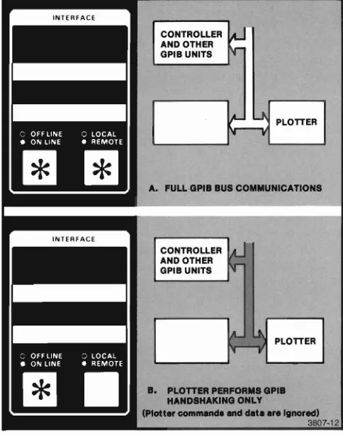
ONLINE REMOTE. With both lights on, full GPIB communications are established; all lines on the GPIB bus are active. This is the normal mode of operation and the mode automatically selected at power-up. See Figure 3-4a.
ONLINE LOCAL. With this light combination, the Plotter receives but ignores all Plotter commands. GPIB bus handshaking signals are recognized by the Plotter. See Figure 3-4b.
NOTE
If either OFFLINE REMOTE or OFFLINE LOCALis
selected, the Plotter disregards al/ GPIB informa-tion. This isequivalent to removing the GPIB cable from the rear panel connector.
INTERFACE
CONTROLLER ~-AND OTHER
~
GPIB UNITS
1.4-
U
PLOTTER1"-
..
A. FULL GPIB BUS COMMUNICATIONS
CONTROLLER AND OTHER GPIB UNITS
PLOTTER
B. PLOTTER PERFORMS GPIB HANDSHAKING ONLY
(Plott...c:ommMCIeMeldllte .... Ignored)
3807·12
Operating the SHIFT and FUNCTION
Switches
The SHIFT and FUNCTION switches, shown in Figure 3-5, permit selection of a variety of Plotter operations. These operations are described later in this section.
There are six FUNCTION switches, labeled RESET, MEDIA, PLOT CONTROL, LOWER LEFT, UPPER RIGHT, and POINT. Notice that above each FUNCTION switch are four labels. The top tabel is the name of the switch. The three labels directly above each switch identify each of the possible switch functions.
The SHIFT switches are the two left most switches within the Control Matrix. Though not labeled on the Plotter, the lower switch is referred to as SHIFT 1 anc the upper switch as SHIFT 2. These SHIFT switches act similar to the shift key on a typewriter; they allow you to select from three functions of anyone FUNC-TION switch. Lights within each SHIFT switch flash when the switch is active.
NOTE
It
is
not necessary to holda
SHIFT switch down when pressing any FUNCTION switch. You need only press the SHIFT switch, release it, then press the desired FUNCTION switch.Examine the first three labels above aach FUNCTION switch. The label immediately above the switch indi-cates the Plotter action performed when only the FUNCTION switch is pressed. To select the Plotter action indicated by the second label above the switch, press SHIFT 1 prior to pressing the desired FUNCTION switch. In the same manner, the Plotter action indicated by the third label is selected by pressing SHIFT 2 and then pressing the appropriate FUNCTION switch.
SWITCH NAMES
SHIFT 2 FUNCTIONS
SHIFT 1 FUNCTIONS
UNCTION SWITCHES&
DICATORS
3807-13
Other Comments
A few additional comments are required to complete the SHIFT and FUNCTION switch operating instruc-tions.
• A SHIFT switch remains active (indicated by a flashing light) for only one selection. The SHIFT switch must be pressed each time a shifted function is selected. Either SHIFT switch can be canceled simply by pressing the lighted switch a second time.
• You can change from one SHIFT switch to another by pressing the desired SHIFT switch. The first SHIFT switch is automatically turned off and the Iight goes out.
• If a switch without a defined shifted function is pressed and a SHIFT switch is active, the SHIFT switch will be canceled (light goes out) and no action occurs.
Examples
The following examples of PLOT CONTROL switch operation demonstrate three ways to use the SHIFT and FUNCTION switches.
To select the Pause function (normally only used when actually plotting):
1. Press only the PLOT CONTROL switch (the light will begin flashing).
2. Wait - if actively plotting, the Plotter may execute a few MOVES and DRAWS before it stops.
3. Press the PLOT CONTROL switch a second time to cancel the Pause function (flashing light stops).
To select the Outline Viewport function (only used when not plotting):
1. Press SHIFT 1 (the lower SHIFT switch). 2. Press the PLOT CONTROL switch.
The Plotter will draw the boundaries of the current Viewport.
To select the Mark Viewport function (only used when not plotting):
1. Press SHIFT 2 (the upper SHIFT switch). 2. Press the PLOT CONTROL switch.
RESET SWITCH INDICATIONS AND
FUNCTIONS
The RESET switch includes two light indications (the non fatal and fatal error indications) and three func-tions (Error Reset, Data Reset, and Initialize funcfunc-tions)
Reset Light Indications
The Reset light indicates either a nonfatal or a fatal error. The two indications and the appropriate action are described here .
• Flashing Light - indicates that one or more non-fatal errors have been detected. Processing of commands continues with no operator action re-quired. The flashing light can be cleared by pressing the RESET switch to initiate t'le Error Reset func-tion. The Error Reset function also clears the error code, the count, and the parameters accessible via the Parameter Entry Card.
• Steady Light - indicates that a fatal error has occurred and processing of commands has halted. A fatal error is cleared by turning the POWER switch off and on after correcting the source of the error
If the Parameter Entry Card is pushed fully in and an error occurs, the binary error code is displayed by the lights on the Parameter Entry Module. Other
information about the errors is available via the Param-eter Entry Module lights. (See the description of the Parameter Entry Card's Error Data line, later in this section.) The error codes are listed in Appendix C. The
4663 Programmer's Manualincludes additional error
information.
NOTE
The Parameter Entry Card should be kept fully inserted to allow the error code to be read regardless of the error type.
Error Reset Function
The Error Reset function performs two tasks:
• Clears any error data accessable via the Parameter Entry Module.
• Turns off the flashing Reset light.
See the descri ption of the Error Data line on the Parameter Entry Card for additional information about the error data.
Data Reset Function
The Data Reset function clears the Plotter's input buffer without resetting any programmable parameter values. In addition, Data Reset causes the following:
• Allows execution of commands that have completed the input buffer processing.
• Continues plotting (if data continues to be received) using data supplied subsequent to the Data Reset.
• Sets the local data reset bit in Device Status WordO. (Refer to the description of the READ STATUS command in the 4663 Programmer's Manual.
The following Plotter actions can be terminated by the Data Reset function: self-test, arc drawing, circle drawing, programmable macro execution, and axis drawing. For any action that is not terminated, the Data Reset will be performed at the completion of the action.
NOTE
If Data Reset is selected while the Plotter is
receiving
a
continuous stream of commands, theInitialize Function
The Initialize function clears a communications prob-lem without reinitializing the Plotter.
The Initialize function also reestablishes the pen carriage position. The pen carriage is moved to a known position (the upper-right corner of the platen) and its position is set to the known coordinate values. This may be necessary if the pen carriage is blocked or bumped with enough force to cause a loss of axis orientation. The local position modification and local data reset bits in Device Status Word 0 are set (refer to the description of the READ STATUS command in the
4663 Programmer's Manual).
To use the Initialize function to recover from a com-munications problem, proceed as follows:
1. Interrupt the host computer or controller to suppress further commands.
2. Activate the Initialize function on the Plotter. 3. Restart the host computer or controller.
The action of the Initialize function is interface depen-dent; the action for each interface (Serial and GPIB) is discussed in the following text.
When the Serial Interface is active, the Initialize function causes the following:
• The Plotter switches communications from Block mode to Continuous mode.
• The input buffer is cleared of commands.
• Pending interface communications (such as a DC 1/DC3 control character or a Block mode block acknowledge character) are cancelled.
NOTE
Ifthe Initialize function is used in conjunction with
a
OCt /OC3 control character, it may benecessaryto send a°1 (CTRL 0) from the
terminal to enable the host computer to resume communications with the Plotter.
• The INTERFACE switches are set to ONLINE RE-MOTE.
• The Plotter turns the interface logically off (equiva-lent to DEVICE OFF command).
• Any pending output messages are canceled.
• Cancels any operator digitize enable or reesta-blishes any permanent enable.
• Turns off the Point light (except for Serial
Command/Response Formats 3 and 4 when opera-tor digitize is permanently enabled).
• Pen 1is selected with the pen in the raised position.
The Initialize function does not modify any current programmable interface parameters, such as prompt character, signature character, and turnaround delay time.
When the GPIB interface is active, the Initialize func-tion causes the following:
• Clears the input buffer.
• Sets the INTERFACE switches to ONLINE REMOTE.
• Cancels any operator digitize enable (or re-estab-lishes any permanent enables).
• Cancels any Talk or Listen enables (unless the interface mode is Talk Only or Listen Only).
• Cancels any pending output messages.
• Pen 1 is selected with the pen in the raised position.
• Cancels any SRQ message or serial poll enables.
• Turns off the Point tight (except for GPIB
MEDIA SWITCH INDICATIONS AND
FUNCTIONS
The MEDIA switch includes two light indications (flash-ing or on steady) and three functions. Two of the functions, Manual Motion and Form Length, require the Media Advance Option (Option 36) and the Media Form line on the Parameter Entry Card must be set to ROLL.
Media Light Indications
The Media light, whether flashing or on steady, may be turned off by pressing the MEDIA switch.
A flashing Media light has two possible meanings, depending on whether SHEET or ROLL is selected on the Media Form line of the Parameter Entry Card.
1. If the Media Form line on the Parameter Entry Card is set to SHEET, a flashing Media light indicates selection of the Media Change function. With Media Change selected, the electrostatic hold-down is off and the sheet media can be changed. Read the description of the Media Change function later in this section.
2. If the Media Form line on the Parameter Entry Card is set to ROLL, a flashing Media light indicates selection of the Form Length function. The Form Length function is described later in this section.
A Media light turned on steady indicates selection of the Manual Motion function. Manual Motion enables movement of the media using the Joystick, as de-scribed later in this section.
NOTE
On instruments that include Option36(Media
Advance), an Out-of-Media condition is indicated by
a
flashing Pause light, not by the Media light.Media Change Function
Selecting Media Change causes two different operations, depending on whether SHEET or ROLL is selected on the Media Form line of the Parameter Entry Card. (ROLL can be selected only on Plotters with the Media Advance Option installed.)
With SHEET selected on the Parameter Entry Card, selecting Media Change causes the following:
• Moves the pen carriage to the upper-right corner of the platen (this position is called the load point).
• Turns the electrostatic hold-down off.
• Flashes the Media light.
To cancel the Media Change function, press the MEDIA switch a second time. This turns the electrostatic hold-down on, turns off the flashing Media light, and allows plotting to resume.
NOTE
Ifit is necessary to smooth the media before plotting resumes, press the PLOT CONTROL switch to select the Pause function before press-ing the MEDIA switch the second time. This turns the electrostatic hold-down on but inhibits plot-ting until Pause is deactivated. See the Pause function description later in this section.
With the Media Advance Option installed and ROL.L selected on the Parameter Entry Card, Media Change advances a length of media across the platen. When the MEDIA switch is pressed, the following occurs:
• The pen holder moves to the load position.
• A fresh section of the roll media is moved onto the platen. The length of the new section of media is determined by the current form length parameter. This parameter is modified by Parameter Entry Card settings, by the SET FORM LENGTH command, or by the Form Length function. The Form Length function is described later in this section.
Manual Motion Function (Requires Option
36)
This function requires the Media Advance Option and selection of ROLL on the Media Form line of the
Parameter Entry Card. Manual Motion has several uses, including:
• Moving a random length of the roll media onto the platen.
• Aligning preprinted media with the index arrow on the lower media guide.
• Moving a group of completed plots to the left side of the Plotter to prepare for separation of the plots using the paper tear bar.
When the Manual Motion function is selected, the following occurs:
• The Media light turns on steady and the pen carriage moves to the load point.
• The X-axis of the Joystick is enabled so the operator can advance the media across the platen. The rate of advance is proportional to the angle of Joystick deflection; maximum speed is obtained by moving the Joystick to the extreme left or right.
To disable this function, press the