3D SPATIAL OBJECT DATA STRUCTURE
Harith Fadzilah Abd Khalid
Alias Abdul Rahman
Department of Geoinformatics,
Faculty of Geoinformation Science and Engineering,
Universiti Teknologi Malaysia, 81310 UTM Skudai, Johor, Malaysia.
ABSTRACT
This paper describes the data structuring for 3D objects and incorporate with spatial geo-database. Spatial geo-database is used to manage large spatial data sets that able to provide access to multi users. Today there are growing tendency towards the multifunctional use of space i.e. above and below the ground surface. Current applications such as urban planning, telecommunication and utility providers need 3D spatial data. Thus, the need for managing the 3D spatial datasets especially for large area is inevitable. A discussion on how to establish these data structures for managing 3D spatial objects of large areas form major discussion of this paper. 3D primitives like points, lines, surfaces (or polygons) and solids are part of the primitives. The mapping of this structure in Oracle Spatial DBMS will be highlighted as well. Our presentation also will highlight the future outlook of the data structuring approach for managing large volume of 3D spatial objects and relates with current research development in 3D GIS.
1.0 INTRODUCTION
The surrounding that we live in actually consists of abundance of 3D spatial objects. Lately there is a demand in applications such as urban planning (Cambry, 1993), telecommunications and cadastres (Stoter, 2000) which depend on 3D data. These applications made complicated because of the tendency towards the multifunctional use of space such as buildings above roads and railways and bridges (Stoter, 2000). Presently the way we manage and administer these 3D spatial objects is through Data Base Management Systems (DBMSs) or specifically Geo-DBMS where these 3D spatial objects are treated as 2D spatial objects. Although the present Geo-DBMS do not support 3D primitive, 3D spatial objects can be modelled with 2D primitive polygons. With several 2D polygons bound a 3D object, it can be stored in one record (multi-polygons) or multiple records (Stoter and Zlatanova, 2003). This is achievable because Geo-DBMSs support 3D coordinates.
2.0 SPATIAL GEO-DBMS
Basically DBMS was designed for non-spatial data. Until the last several years, developments of DBMS were significant to cater the spatial data. According to Bruenig et al. (2004), there are two approaches of development in DBMS linking to spatial data. The first is the ‘top-down’ approach. In this approach, the DBMS functionality has been constructed ‘under’ the GIS application and the GIS application accesses ‘top-down’ to the geodata stored in the DBMS. ESRI is one of the GIS vendors that initially implementing this approach to store both non-spatial and spatial data.
The other development of DBMS is the ‘bottom-up’ approach. In this approach, the DBMS supports the spatial data type; meaning that it extends ‘low level’ DBMS data type and indexes to use them in the upper level of GIS applications. Data analysis on the spatial and non-spatial parts of objects can be executed. Lately more and more commercial DBMSs provide spatial extensions to support spatial objects.
In other word, a full-fledged DBMS which has capabilities for handling spatial data is also called Geo-database or Geo-DBMS (Gunting, 1994). A Geo-DBMS knows primitive and composed geometric data types i.e. point, line and polygon, in the same way as its primitive standard data types such as character, string, integer, real etc. Presently the implementations of spatial data type in mainstream DBMSs are basically 2D and the spatial features are stored in a geometrical model without the internal topology. Topological relationships between geometries can be retrieved by the use of spatial operators.
3.0 GEOMETRICAL MODEL IN ORACLE SPATIAL
Oracle, IBM DB2, Informix and PostGIS support geometric functions defined by OGC (Oosterom et al., 2002). OGC specifications (OGC, 2001) are until now 2D and the implementations of spatial data types in mainstream DBMSs stated above are actually in 2D, but some of these DBMSs capable of supporting 3D coordinates in their spatial data type. The standard SQL statement “select attribute_a from table_b where a<100” is the same in every DBMS, however, if geometries are concerned, different types of queries have to be executed in different DBMSs. For example, Oracle Spatial does not have explicitly implemented data types such as point, line and polygon. There is only one complex data type, SDO_GEOMETRY, composed of several parameters including type geometry, dimension, and an array with the x, y, z coordinates.
Spatial is an element. Points, lines and polygons are the primitive elements which are stored by their x and y coordinates. To model a spatial feature, a single element or a collection of homogeneous or heterogeneous elements to is used to form a geometry object. Oracle used a variety of geometric types (point, linestring, polygon, multipoint, multi linestring, multipolygon). A geometry is stored as an object in a single row, in a column of type SDO_GEOMETRY. Oracle Spatial defines the object type SDO_GEOMETRY as:
CREATE TYPE sdo_geometry AS OBJECT ( SDO_GTYPE NUMBER,
SDO_SRID NUMBER, SDO_POINT SDO_POINT_TYPE,
SDO_ELEM_INFO MDSYS.SDO_ELEM_INFO_ARRAY, SDO_ORDINATES MDSYS.SDO_ORDINATE_ARRY);
SDO_GTYPE indicates the type of the geometry (point, linestring, polygon, multipoint, multilinestring, multipolygon). SDO_SRID is a reference to the spatial reference system used for the ordinates. SDO_ELEM_INFO is defined using a varying length array of numbers. These attributes show how to interpret the ordinates stored in the SDO_ORDINATES attribute. They include for every element the offset where the element starts in the array, type of element (point, linestring consisting of straight lines, linestring consisting of circular arcs, polygon) and an interpretation code. One geometry object composed of one or more elements.
10 (10, 40)
(5, 20) (10, 20)
SDO_GEOMETRY Column = ( SDO_GTYPE = 2003 SDO_SRID = NULL SDO_POINT = NULL
SDO_ELEM_INFO = (1,1003,1)
SDO_ORDINATES = (5,20, 10,20, 10,40, 5,40, 5,20))
In SDO_GTYPE =2003, the 2 indicates two-dimensional and the 3 indicates a polygon. In SDO_ELEM_INFO, the final 1 in 1, 1003, 1 indicates that this is a polygon containing straight lines. Also the first position (‘1’) indicates that the first element (in this case only one polygon) starts at offset 1 in the coordinate list.
To elaborate further, let see how a box is stored as a geometry in Oracle (SDO_GEOMETRY type) in the ‘geom2d’ table and progress further the same box with height 50 stored in the ‘geom3d’ through SQL statements. These tables are representing the geometries of the object.
create table geom2d (
shape mdsys.sdo_geometry not null, ID number (11) not null);
create table geom3d (
shape mdsys.sdo_geometry not null, ID number (11) not null);
/* inserting the data */
/* a 2D box */
insert into geom2d (shape, ID) values ( mdsys.SDO_GEOMETRY (2003, NULL, NULL, mdsys.SDO_ELEM_INFO_ARRAY(1, 1003, 1),
mdsys.SDO_ORDINATE_ARRAY(0,0, 100,0, 100,100, 0,100, 0,0)), 8);
/* a 3D box */
insert into geom3d (shape, ID) values ( mdsys.SDO_GEOMETRY (3003, NULL, NULL, mdsys.SDO_ELEM_INFO_ARRAY(1, 1003, 1),
mdsys.SDO_ORDINATE_ARRAY(0,0,50, 100,0,50, 100,100,50, 0,100,50, 0,0,50)), 9);
The metadata table for the geometries is maintained in Oracle which describes the dimension, lower and upper bounds and tolerance in each dimension. The following shows how the information on the tables, geom2d and geom3d inserted in the metadata table. And finally a spatial index (r-tree) is created on the tables (to speed up spatial queries)
/* inserting metadata */
insert into user_sdo_geom_metadata values (‘GEOM2D’, ‘SHAPE’, mdsys.SDO_DIM_ARRAY ( mdsys.SDO_DIM_ELEMENT (‘X’, 0, 500, 0.5), mdsys.SDO_DIM_ELEMENT (‘Y’, 0, 500, 0.5)), NULL);
/* 3D table */
insert into user_sdo_geom_metadata values (‘GEOM3D’, ‘SHAPE’, mdsys.SDO_DIM_ARRAY ( mdsys.SDO_DIM_ELEMENT (‘X’, 0, 500, 0.5), mdsys.SDO_DIM_ELEMENT (‘Y’, 0, 500, 0.5), mdsys.SDO_DIM_ELEMENT (‘Z’, 0, 300, 0.5)), NULL);
/* creating index */
/* 2D table */
create index GEOM2D_I on GEOM2D(SHAPE) indextype is mdsys.spatial_index;
analyze table GEOM2D compute statistics;
/* 3D table */
create index GEOM3D_I on GEOM3D(SHAPE) indextype is mdsys.spatial_index
parameters(‘sdo_indx_dims=3’);
analyze table GEOM3D compute statistics;
4.0 HOW 3D OBJECTS REPRESENTED IN ORACLE SPATIAL
geo-DBMS: using the existing data types or creating user-define spatial types. In this paper we will discuss on the first approach. In this approach the 3D objects are represented as a set polygons (with 3D coordinates) composing the object. This approach also has the advantage of being ‘understandable’ for all the front-ends (GIS/CAD/AEC) since it is supported by the DBMS. In Oracle Spatial, 3D object can be represented as polyhedron (body with flat faces) which is 3D polygon stored as a list of polygons or as multipolygon (one polygon consisting of several polygons). Figure 1 is the UML class diagram that shows the data structure of polyhedron data model.
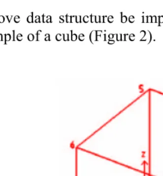
To show the above data structure be implemented in Oracle Spatial, lets take an example of a cube (Figure 2).
Figure 2: Cube to be stored in the Oracle Spatial (Stoter et. al. 2002)
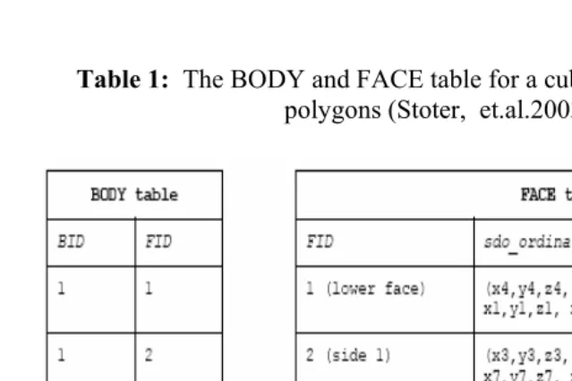
Table 1: The BODY and FACE table for a cube is stored as a set of polygons (Stoter, et.al.2003)
Table 2: BODY table for a cube is stored as one multipolygons (Stoter, J. et.al.2003)
5.0 CONCLUSION
Currently, GIS is changing and becoming an integration of database management, powerful editing and realism visualization cause by the advanced computing development. At current status, 3D GIS mostly focus on the geometrical rather that the topological aspect. The above geometric approach of using set of polygons as polyhedron for the data structure is encouraging us to model a large volume of 3D spatial objects and managing them in a proper manner in a Spatial geo-DBMS. This could be possibly done by the help of Light Detection and Ranging (LIDAR) technology and photogrammetry method which capable of capturing 3D data set in large area. Even though 3D spatial object modelled by the method stated above and manageable in Spatial geo-DBMS, it still lack of real true 3D data type (3D volumetric) which can function in a proper 3D environment function such as validation, volume, length, intersection, overlap, etc (Abdul-Rahman et. al, 2002).
Our future works will be on how to use these data structure and manage the 3D spatial objects in a Spatial geo-DBMS. This will definitely relate to designing the Spatial geo-DBMS, spatial indexing and also the visualization with front-end application software.
REFERENCE
Arens, C., J. Stoter, P.v. Oosterom (2005). Modelling 3D spatial objects in a geo-DBMS using a 3D primitive. In Computer & Geosciences 31 (2005) pp. 165-177.
Bruenig, M and Zlatanova, S. (2004). 3D-GeoDBMS, Directions Magazine.
Cambray, B., (1993). Three-dimensional modeling in a geographical database. In: Proceedings 11th International Conference on Computer Assisted Cartography, MN, USA, pp. 338-347.
Güting, R.H, (1994). An Introduction to Spatial Database Systems. VLDB Journal Vol. 3 no. 4, pp357-399
IBM (2000). IBM DB2 Spatial Extender User’s Guide and Reference. Special web relese edition.
Informix (2000). Informix Spatial DataBlade Module User’s Guide, Part no. 000-6868.
Ingres (1994). INGRES/Object Management Extension User’s Guide, Release 6.5 (1994). CA-OpenIngres.
OGC (1998). The OpenGIS Guide, Third edition. An introduction to Interoperable Geo-processing. The OGC Project Technical Committee of OpenGIS Consortium, edited by Buhler and K. McKee, L., Wayland, Mass., USA
OGC (1999). OpenGIS Simple Features Specification for SQL. Revision 1.1, OpenGIS Project Document 99-049
OGC (2001). OpenGIS Specification, 2001, available on http://www.opengis.org/techno/spec.htm.
Oosterom, P. v, J. Stoter, W. Quak and S. Zlatanova, (2002). The balance between geometry and topology, in: Advances in Spatial data Handling, 10th International Symposium on Spatial Data Handling, D. Richardson and P. van Oosterum (Eds.), Springer-Verlag, Berlin, pp. 209-224
Oracle (2001). Oracle Spatial User’s Guide and Reference Release 9.0.1 Part Number A88805-01, June 2001
Common Problems-Common Solutions’, vol. III, Delft, The Netherlands, pp. 43-58.
Stoter, J.E and Zlatanova (2002). 3D Large Scale Modelling, Workshop on 3D cadastre and Large Scale Modelling, organized during UDMS 2002, October 2002, Prague, Tsjech Republic Stoter, J. E, Zlatanova, S., (2003). Visualising and editing of 3D