R E S E A R C H
Open Access
Performance enhancement of wireless mobile
adhoc networks through improved error
correction and ICI cancellation
Zeeshan Sabir
*, M Inayatullah Babar and Syed Waqar Shah
Abstract
Mobile adhoc network (MANET) refers to an arrangement of wireless mobile nodes that have the tendency of dynamically and freely self-organizing into temporary and arbitrary network topologies. Orthogonal frequency division multiplexing (OFDM) is the foremost choice for MANET system designers at the Physical Layer due to its inherent property of high data rate transmission that corresponds to its lofty spectrum efficiency. The downside of OFDM includes its sensitivity to synchronization errors (frequency offsets and symbol time). Most of the present day techniques employing OFDM for data transmission support mobility as one of the primary features. This mobility causes small frequency offsets due to the production of Doppler frequencies. It results in intercarrier interference (ICI) which degrades the signal quality due to a crosstalk between the subcarriers of OFDM symbol. An efficient frequency-domain block-type pilot-assisted ICI mitigation scheme is proposed in this article which nullifies the effect of channel frequency offsets from the received OFDM symbols. Second problem addressed in this article is the noise effect induced by different sources into the received symbol increasing its bit error rate and making it unsuitable for many applications. Forward-error-correcting turbo codes have been employed into the proposed model which adds redundant bits into the system which are later used for error detection and correction purpose. At the receiver end, maximuma posteriori(MAP) decoding algorithm is implemented using two component MAP decoders. These decoders tend to exchange interleaved extrinsic soft information among each other in the form of log likelihood ratio improving the previous estimate regarding the decoded bit in each iteration.
Keywords:MANET, OFDM, Channel equalization, Intercarrier interference (ICI), PCCC encoder, MAP decoder, Channel estimation, Turbo codes
Introduction
Mobile adhoc network (MANET) represents a set of wireless mobile nodes that have the capability of com-municating with each other without the help of a pre-existing infrastructure [1]. Power consumption is an im-portant issue in MANETs due to high dependence of mobile devices on battery power. A high data rate trans-mission technique like orthogonal frequency division multiplexing (OFDM) is ideal for MANETs at the Phys-ical Layer due to its spectral efficiency. A number of applications like 802.16e (WiMax), 802.11a/g (WLAN), 802.11n (WiFi), etc., uses the multicarrier OFDM tech-nique due to its bandwidth-efficient nature. OFDM is a very strong competitor for the Next Generation (4 G)
Wireless Communication techniques [2]. A peak data rate upto 54 Mbps can be supported by using commer-cial wireless local area network (WLAN) based on OFDM [3].
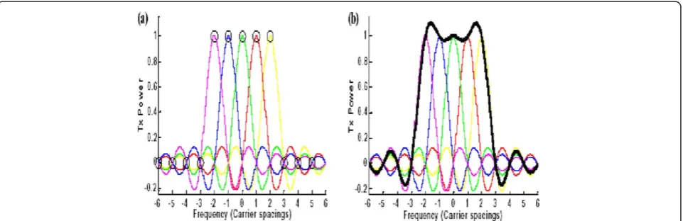
The subcarriers of OFDM system overlap in frequency-domain, and this property dictates its bandwidth effi-ciency. Figure 1a shows that orthogonality which is the nub of OFDM is maintained in the inverse fast Fourier transform (IFFT) block for the same OFDM symbol, by aligning peak of one subcarrier with the nulls of the others. Figure 1b shows an envelop of subcarriers which modulates in the IFFT block to form one OFDM symbol.
Intersymbol interference (ISI), which refers to the aliasing between OFDM symbols, is prevented by the introduction of a guard interval (GI) between the adja-cent OFDM symbols. Length of the GI has a major
* Correspondence:[email protected]
University of Engineering& Technology, Peshawar, Pakistan
impact on the ISI mitigation capability of the system. For mitigating the effects of ISI efficiently, the length of the GI should be chosen greater than the delay spread of the channel which refers to the time lapse at the receiver amid arrival of first and the last multipath components.
On the other side, major cause for intercarrier interfer-ence (ICI) is the Doppler frequency generated due to the relative motion between transmitter and receiver. Be-cause of the relative mobility between transmitter and receiver, the received number of frequency cycles is dif-ferent from the transmitted one. The difference in the number of frequency cycles tends to commove the align-ment of peaks and nulls of subcarriers. This misalign-ment of peaks and nulls of subcarrier originate carrier frequency offsets that generate ICI in the system.
Turbo codes introduced in 1993 [4] first time gave the idea of channel codes that can possibly work in 0.5 dB range of the Shannon capacity limit. Turbo codes tend to add redundant information into the message bits that is later used at the time of decoding for improving the final estimate regarding the transmitted information. Two or more parallel concatenated recursive systematic convolutional (RSC) encoders constitute the basic struc-ture of turbo codes. These RSC encoders are separated in parallel by an interleaver, that tends to spread any possible error, uniformly over all the generated bit stream, thus avoiding the infection of a single user or group of users from effect of the error. At the receiving
side an iterative mechanism, based on maximum a
pos-teriori (MAP) algorithm [5], is employed to decode the bits. We have incorporated turbo codes into the pro-posed OFDM model to palliate channel-induced noise effects from the transmitted OFDM symbols.
Various models have been proposed for OFDM con-cerning mitigation of ICI and error correction. A self-ICI cancellation scheme has been purposed in [6] in which an idea of giving diverse weights to the same data symbol is proposed. ICI has notably been cancelled-out
by modulating alike data symbol on the neighboring subcarriers and assigning dissimilar weights to them at the transmitter end. Maximal ratio combining algorithm is implemented at the receiver side to combine all these copies. In spite of well cancellation of ICI, high wastage of bandwidth dismisses the usage of this algorithm in the practical systems.
Jeon et al. [7] proposed an ICI cancellation model that is founded on the basic supposition that change in impulse response of the channel remains linear inside an OFDM symbol. Their proposed model was appropriate and ap-plicable for low mobile environments only. It is because for the low mobile environments, channel exhibit a slow fading. Therefore, the impulse response variation for the same OFDM symbol can be considered linear. But for the high mobile environments, impulse response variations do not remain linear inside an OFDM symbol. It is because the channel follows a fast fading distribution. And thus we have to consider the fading occurring at each of the sub-carrier independently irrespective of its neighboring subcarriers.
A multi-rate sampling theory is proposed by Chayrat-sami and Wickert [8]. This theory is applied at the re-ceiving end and it focuses the extended outer spectrum of the OFDM subcarriers to decrease the interference. The interference between the remaining subcarriers of the OFDM is mitigated by applying a sequential interfer-ence cancellation (SIC) algorithm. A 10e-2 bit error rate (BER) performance is reported in the results at afford-able SNR. The inherent latency and the high computa-tional complexity involved in the processing of SIC algorithm dismiss the realistic implementation of the theory.
Li et al. [9] presented an adaptive minimum mean square error (MMSE) channel estimator. This estimator investigates the correlation of a dispersive channel fre-quency response over frefre-quency-domain and time-do-main. Again the computational complexity required for
computing this correlation results in a notable delay which prevents the use of the proposed model for real-time services.
In this article, we propose a novel channel equalization technique based on frequency-domain block-type pilot-assisted channel estimation (PACE) strategy that uses turbo detection-based approach at the receiver side. In the presented scheme, the information symbol detection phase is accomplished with the help of iterations of the error-correcting codes. We employed turbo codes in our presented OFDM model due to their improved error-correcting performance over the contemporary channel codes [10,11]. Turbo codes consist of parallel concatenation of RSC encoders. The number of parallel RSC encoders depends upon the coding rate that we want to achieve in our system. MAP algorithm-based decoder is used at the receiver side due to its better per-formance [12]. It decodes the received data bits using the iterations of the component MAP decoders. The two
component MAP decoders exchanges a soft (a priori)
information between each other during each iteration. This exchange of information leads to an improved esti-mate of the decoded bit as the iterations carry-on. Final estimate is made based upon the MAP probability calcu-lated by the component MAP decoder no. 2. This results in a considerable performance enhancement of the sys-tem in each iteration by lowering of BER.
The rest of the article is organized as follows.“System model” section explains in detail the proposed system model along with its mathematical manipulations. “ Al-gorithm for channel estimation and equalization”section incorporates the explanation of the channel estimation and equalization algorithm used in the presented model.
“Anatomy of encoder and decoder” section contains the detail explanation of the structure of turbo encoder and MAP decoder used at the transmitter and receiver side, respectively. Simulation results have been discussed in
“Simulation results” section and “Conclusions” section concludes the study.
System model
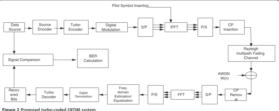
Figure 2 shows the proposed system model. First of all message bit sequence is passed through a source en-coder which works as a compression block and converts the analogue message signal into binary digits with mini-mum redundancy. Any suitable source encoder, e.g., Huff-man coder, can be used for performing this task. After this step the message bit sequence is passed through channel coding block for adding redundant bits for error detection and correction. In our case, we have used a rate 1/3 turbo encoder. Structure of the turbo codes is discussed in
“Anatomy of encoder and decoder”section in detail. After adding redundancy, the bits are digitally mapped and S/P converted. The digitally mapped symbols are then fed to
theN-ptIFFT block, which producesXp(k) symbol at the output havingNsubcarriers given by [13]
Xpð Þ ¼k Xpð Þ0 ;Xpð Þ1 ;Xpð Þ2 ;. . .;XpðN1Þ
T
ð1Þ
IFFT block is responsible for generation of orthog-onal subcarriers and modulation of digitally mapped
data symbols on these subcarriers. For n subcarriers
(Vn = 0,1,2,. . .,N – 1) the OFDM-modulated symbol
generated at the output of N-pt IFFT at time instant
p is given by
Xpð Þ ¼k
1 N
X N1
n¼0
x nð Þe2Nπj ð2Þ
where Xp (k) is given by (1). x(n) shows the signal at the output of the nth tap of IFFT block. This step is
known as “OFDM modulation”.
During this process, the pilot symbols are inserted in parallel and at the receiving end they are used for calcu-lating H matrix which consists of channel estimates for different subcarrier positions and is later used for data equalization. Next cyclic prefix, also called GI, is affixed with each OFDM symbol, i.e., lastLsymbols ofXp(k) are appended to the start of each transmitted OFDM block
eXpshown as
eXp¼Xpð Þk NLcpþ1;Xpð Þk ð3Þ
whereLcpis the length of the cyclic prefix and N
repre-sents the size of the IFFT block. Semicolon between the two terms shows that the first portion of the symbol is appended to the second symbol at the start. It is same as
being done in MATLAB
®
.As we have discussed earlier in the first section, the necessary condition for the GI length for completely
mitigating the effect of ISI isD≤L, i.e., the GI lengthL
must be chosen such that its value should be at least equal to the channel delay spread.
In order to imitate the effect of real channel, Rayleigh fading additive white Gaussian noise (AWGN) channel has been simulated after passing through which, signal at the receiver side is given by
y nð Þ ¼X
L1
l¼0
h nð Þ;l x nð lÞ þw nð Þ ð4Þ
whereLrepresents the total number of discrete multiple paths for the Rayleigh fading channel, h(n,l) shows the fading channel impulse response and w(n) depicts the receiver added AWGN noise at instantn.
from the orthogonal subcarriers and the signal at the output of this block is given by [4]
Y mð Þ ¼X
N1
k¼0
XL1
l¼0
XkHlðmkÞe j2πkj
N þWm ð5Þ
Where Wm represents the FFT of the AWGN noise
WnandHl(m−k)represent the FFT of the Rayleigh fading channel impulse response given by
HlðmkÞ¼
1 Nhn;le
j2πðmkÞ
N ð6Þ
The data symbols after being demodulated from the
orthogonal subcarriers are fed to the channel
equalization/estimation block which uses pilot tones to remove the effects of impulse response offered by the channel from the received signal. As discussed in“ Algo-rithm for channel estimation and equalization” section,
efficient pilot tones’ placement in an OFDM symbol
plays an important role in the performance improve-ment of the channel estimator against the AWGN multi-path Rayleigh fading channel. Finally, decoding of the bits is carried-out by passing them through iterative decoding portion of the receiver. The decoder is based on MAP algorithm which efficiently decodes the bits using two component MAP decoders by exchanging soft information between them. This step helps improve the decoding efficiency by using the previous estimates of the decoded bit in each iteration. In order to compute the BER performance of the system, the decoded signal is then passed through a signal comparator which takes as input the original user data bits and the decoded data bits. Finally, BER is computed using these two values in the signal comparator. The proposed OFDM model has been tested by changing the number of
iterations of MAP decoder and evaluating and compar-ing its performance under four different digital modula-tion schemes.
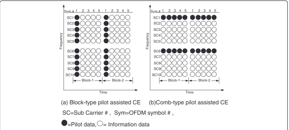
Algorithm for channel estimation and equalization The channel estimation and equalization technique implemented in the proposed system uses PACE ap-proach. In this method, pilot symbols send prior to every data block nullify the impulse response effects offered by the channel from the received data symbols. These pilot symbols use to embed the effect of the channel impairments in them. Equalization technique implemen-ted at the receiver uses these channel impairments to compensate the effects of the impulse response offered by the channel from the received user data. Pilot tones’ place-ment in the symbol cast a great impact on the channel es-timator performance. In our proposed model, we have used pilot-assisted block-type single-dimensional fre-quency-domain channel estimation strategy [14] as shown in Figure 3a. The system overhead for channel estimation was calculated as 14.3%.
Instead of evenly spreading the pilot tones over all the transmitted data block such that some of the sub-carriers in each data block are dedicated for sending the pilot data, as being done in comb-type estimator (Figure 3b), we used block-type estimation approach where some of the symbols are dedicated for sending pilot data while the user data are carried on rest of the symbols. Block-type channel estimator is the clos-est competitor of comb-type clos-estimator, but the prob-lem in comb-type pilot-inserted channel estimator is that it uses interpolation for calculating the channel impulse response at those subcarrier positions where pilot tones are not present. This introduces an interpolation error that adds to the overall BER Signal Comparison CalculationBER
Data Source
Turbo Encoder
Digital
Modulation S/P
CP Insertion P/S
IFFT
FFT Recov
ered Bits
Turbo Decoder
Digital Demodultion
Freq-domain Estimation/ Equalization
P/S S/P
CP Remov
al
Rayleigh multipath Fading
Channel Pilot Symbol Insertion
AWGN W(n) Source
Encoder
performance of the model. Channel estimator over-head was same in our case compared to comb-type technique. A schematic comparison of both types of the channel estimators is given in Figure 3 [14].
The upcoming data symbols have been equalized using the cannel taps calculated from the pilot OFDM symbol. This process is repeated on symbol-to-symbol basis until next pilot OFDM symbol arrives in the next data block as shown in Figure 3 above. Figure 4 shows the block diagram for the proposed channel estimator.
As per procedure, computation ofHce, the channel
es-timation matrix is carried-out with the help of received and sent pilot symbols using the relation:
Hce¼Ypð Þk Xpð Þk k¼
0;1;2;. . .;Np1 ð7Þ
Where Xp(k) and Yp(k) represent, respectively, the transmitted and received pilot tones.
The upcoming data equalization is performed by multiplying the inverse of the channel estimation
matrix obtained in the first step with the received data symbol.
Xeð Þ ¼k Y kð ÞHce1 k¼0;1;2;. . .;N1 ð8Þ If the delay elements offer a time delay of t then the equalizer’s frequency response Heq(f) is periodic with a
period of symbol rate while the symbol rate equals 1/t. This shows that it satisfies the Nyquist’s first criterion which states that for achieving a zero ICI with perfect equalization, the pulse shape should be such that it has a non-zero amplitude at its centre (t= 0) and zero ampli-tudes att = ±nT (Vn= 1,2,3,. . .). Thus, in order to opti-mally attain the equalization state, the following condition is mandatory to be followed by the equalizer and frequency response matrix of the channel:
Hchð Þf Heqð Þ ¼f 1:j jf <1
2t ð9Þ
Here Hch(f) represents the folded frequency response
of the channel. Thus, the zero forcing equalizer has been implemented as an inverse filter that equalizes the
Block-1 Block-2
SC1
SC5 SC4 SC3 SC2
SC6
SC10 SC9 SC8 SC7
Sym #1 2 3 4 5
Frequency
Time
Block-1 Block-2
SC1
SC5 SC4 SC3 SC2
SC6
SC10 SC9 SC8 SC7
Sym #1 2 3 4 5
Frequency
Time
2 3 4 5
1 1 2 3 4 5
(a) Block-type pilot assisted CE (b)Comb-type pilot assisted CE
SC=Sub Carrier # , Sym=OFDM symbol # ,
=Pilot data, = Information data
Figure 3Schematic representation of block-type and comb-type pilot tone insertion techniques.
Generated Training Sequence
Received Training Sequence
Reciprocal
Product Reciprocal (k)
Xp−1
c e
H Hc e−1
Product
Y (k)
Xe (k) Xp (k)
Yp (k)
received data symbols impulse response by inverting the folded frequency response of the channel.
The above process is repeated for each data symbol till the effect of ICI is equalized for the whole received sequence.
Anatomy of encoder and decoder
Encoder
We used a 1/3 rate turbo encoder in the suggested OFDM system. The encoder works on the principal of adding redundant information into the source-coded message bits for minimizing the transmission errors. Figure 5 shows the proposed encoder structure. It is made by concatenating in parallel two RSC encoders and using an interleaver in between.
In order to variate the coding rate as per requirement, puncturing is used at the output. After puncturing, the output bit sequence can be represented as
S1P11P21S2P21P22S3P13P32. . .SnP1nP2n
D
D
D
D
D
D
d2,p2,p
Input bit stream Input bit stream
Ck
d1,p1,p
Code Puncturing Code Puncturing
Figure 5A rate 1/3 PCCC turbo code.
Figure 6Trellis diagram for RSC convolutional Enc-1(solid lines represent transition due to 0 and dashed lines represents transition due to 1).
Table 1 The eight possible states for constraint length 3 RSC convolutional encoder
State 1st Delay reg 2nd Delay reg 3rd Delay reg
S1 0 0 0
S2 0 0 1
S3 0 1 0
S4 0 1 1
S5 1 0 0
S6 1 0 1
S7 1 1 0
where the superscript corresponds to the component RSC convolutional encoder number and the sub-script represents the bit number for that component encoder.
The outputsd1,pand d2,prepresent the parity bits con-tributed by the first and second RSC encoders while ds corresponds to the systematic bits. The generator se-quence of the component encoders plays a vital role in the
system’s performance. The feed-forward and
feed-backward generator sequences used in our model are 1 + D+D2+D3and 1 +D+D3[15], respectively.
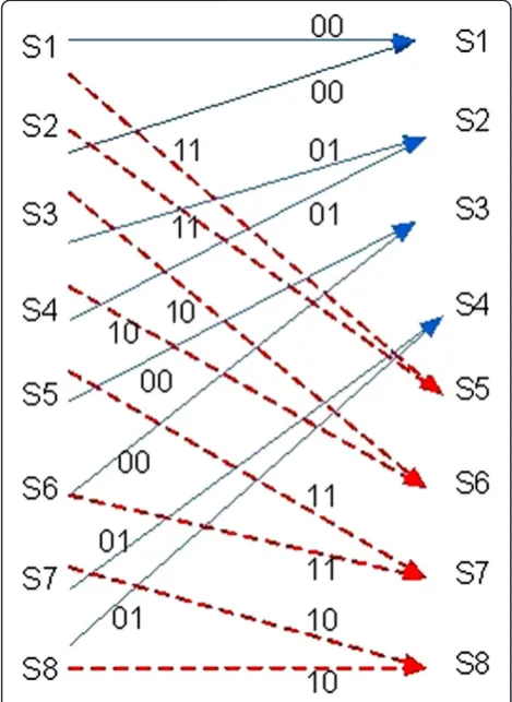
Simplified trellis diagram of the RSC convolutional encoder is mentioned in Figure 6. Whereas Table 1 shows the eight possible states for the constraint length 3 RSC convolutional encoder. The output code word generated by each transition is shown with the transition arrow.
Decoder
Decoder is based on MAP decoding algorithm. Two
serially concatenated component MAP decoders
exchanges a priori soft information via an interleaver as shown in Figure 7 [16].
The exchange of soft information among the two com-ponent MAP decoders is done in an iterative manner. Dec-1 calculates likelihood ratio (LLR) as its soft infor-mation and this inforinfor-mation regarding the decoded bits is fed asa prioriprobability to Dec-2.
LLR uð Þ ¼k 1n P uk¼ þ
1=yN
1
P uð k¼ 1=yN1Þ
ð10Þ
In the first iteration, as a starting value, for Dec-1 the a priori probability for 1 and 0 bits is taken as ½. For the uniform spread of transmission errors, the output of Dec-1 is interleaved and thus produces a better estimate for information sequence of Dec-2. The interleaver pro-vides scrambled information for the second component MAP decoder so that the inputs of the two component MAP decoders should be decorrelated and a suboptimal decoding algorithm based on the decorrelated informa-tion exchange can be applied among the component MAP decoders. Thea posterioriprobability produced by Dec-2 acts as the extrinsic information of the decoded bits for Dec-1 and is fed, via a deinterleaver, to it. Thus, as the iterations carry-on, the final estimate of the de-coder regarding the input bit keeps on improving com-pared to a one iteration hard decision-based serially concatenated decoder. As iterations carry-on, the two
component decoders’ output which is in the form of
their extrinsic information begins to diverge from its starting value of ½. After executingkiterations, the out-put of component MAP decoder # 2 is passed through a hard decision. The value of kis fixed by the system de-signer depending upon the trade-off between the error sensitivity of the system for the application for which it is designed for and the latency, dictated by the computa-tional complexity, tolerable by the system. Non-real-time services are error sensitive but are delay tolerant while real-time services are delay sensitive though error tolerant. Thus, this trade-off is application dependent. MAP
Dec-1
Map Dec-2
cs
c2,p
c1,p
Decoded bits
^1e
^2e
^2
Figure 7Turbo MAP decoder based on two component decoders.
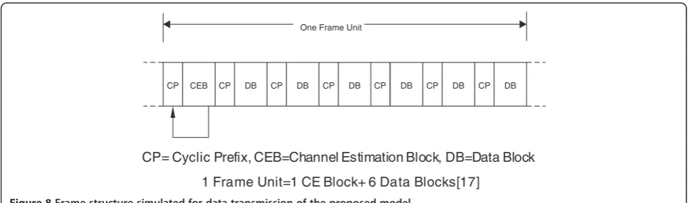
CP CEB CP DB CP DB CP DB CP DB CP DB CP DB
One Frame Unit
CP= Cyclic Prefix, CEB=Channel Estimation Block, DB=Data Block
1 Frame Unit=1 CE Block+ 6 Data Blocks[17]
For a rate 1/ncomponent codeword, first MAP decoder produces the LLR given by [14]
Λ1ð Þ ¼Ct log X
Ms1
l0;l¼0 αt1 l
0
p1
tð Þ1 exp
Xn1
j¼0
rt;jx1t;jð Þl
2
2σ2
0 B B B B @
1 C C C C Aβtð Þl
X
Ms1
l0;l¼0 αt1 l
0
p1tð Þ0 exp Xn1
j¼0
rt;jx0t;jð Þl
2
2σ2
0 B B B B @
1 C C C C Aβtð Þl
ð11Þ
wherept1(0) andpt1(1) area prioriprobability at the input of the component MAP Dec-1 for bit 0 and 1, respectively, and is taken as 0.5 in the first iteration. Similarly, pt2(0) and pt2(1) represent a priori probability at the input for MAP Dec-2. The bit is decoded as a 1 or 0 depending upon the sign of the LLR, in the final iteration. After k iterations, if LLR is positive, bit 1 is decoded and if LLR is negative, a 0 is decoded. These decoding of the bit 1 or 0 corresponds to the inherent property of the log operator which dictates a positive mantissa whenever the numer-ator term of the log is greater than denominnumer-ator and nega-tive mantissa for the vice-versa case.
Simulation results
Using MATLAB
®
simulation, we analyzed the results ofthe introduced model with uncoded and turbo-coded OFDM with the aid of frequency-domain block-type PACE.
Figure 8 shows the frame structure that was simulated for the transmission of OFDM symbols. Rayleigh slow fading frequency-selective AWGN channel has been simulated to analyze the performance of the proposed model.
Test case 1. Uncoded OFDM with PACE
In the proposed model, OFDM was used with a symbol size of 256 subcarriers and ISI effects were vanished with a guard interval length of 64 subcarriers.
As mentioned in Figure 8, every frame unit of OFDM consists of one channel estimation pilot symbol followed by six data symbols. Data rate of the transmission was cal-culated as 69.37, 46.25, 23.15, and 11.57 MHz, respect-ively, for 64-Quadrature Amplitude Modulation (QAM), 16-QAM, Quadrature Phase Shift Keying (QPSK), and Binary Phase Shift Keying (BPSK). 17.4-MHz bandwidth was used to conform with 802.11n standard.
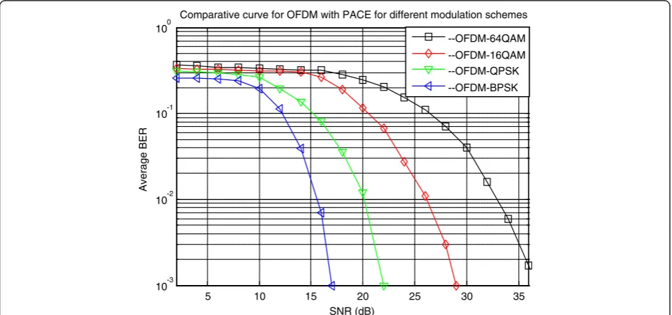
Figure 9 shows degradation in the performance of the system as we move towards higher modulation schemes. The performance degradation is because of close positioning of signal points on the constellation map for higher modulation schemes as shown in Figure 10. The four panels in Figure 10 show the condition of the signal before and after its passage through the simulated channel for the four different modulation schemes men-tioned below each of the panel. In each of the four panels, left graph shows the scatter plot of quadrature over in phase for transmitted signalXwhile on the right graph we see the same plot for received signalY.
We used PACE strategy with 1:6 pilot to data symbol ratio in the proposed model.
5 10 15 20 25 30 35
10-3 10-2 10-1 100
SNR (dB)
Average BER
Comparative curve for OFDM with PACE for different modulation schemes
--OFDM-64QAM --OFDM-16QAM --OFDM-QPSK --OFDM-BPSK
5 10 15 20 25 10-4
10-3 10-2 10-1 100
SNR (dB)
Average BER
Comparison curve for different number of iterations of MAP Decoder for BPSK
1-iter
2-iter
4-iter
8-iter
20-iter
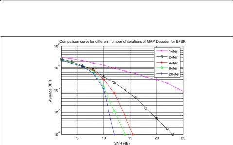
Figure 11Comparison curve of turbo-coded OFDM with PACE for BPSK modulation scheme for different number of iterations of MAP decoder. -1 -0.5 0 0.5 1
-1 -0.5 0 0.5 1
Quadrature
In-Phase Scatter plot
-1 -0.5 0 0.5 1
-1 -0.8 -0.6 -0.4 -0.2 0 0.2 0.4 0.6 0.8 1
Quadrature
In-Phase Scatter plot
BPSK
16-QAM
QPSK
64-QAM
-0.6 -0.4 -0.2 0 0.2 0.4 0.6 -0.6
-0.4 -0.2 0 0.2 0.4 0.6
Quadrature
In-Phase Scatter plot
-0.5 0 0.5
-0.8 -0.6 -0.4 -0.2 0 0.2 0.4 0.6 0.8
Quadrature
In-Phase Scatter plot
-3 -2 -1 0 1 2 3
-3 -2 -1 0 1 2 3
Quadrature
In-Phase Scatter plot
-4 -2 0 2 4
-4 -3 -2 -1 0 1 2 3 4
Quadrature
In-Phase Scatter plot
-6 -4 -2 0 2 4 6 -6
-4 -2 0 2 4 6
Quadrature
In-Phase Scatter plot
-5 0 5
-8 -6 -4 -2 0 2 4 6 8
Quadrature
In-Phase Scatter plot
(a)
(b)
(c)
(d)
Test case 2. Turbo-coded OFDM with PACE
In the Test Case-2 turbo codes were implemented in the same proposed model of OFDM with PACE. In this sec-tion, the system’s behavior has been studied by changing number of iterations for the MAP decoder for different modulation schemes. The same multipath rayleigh fad-ing AWGN channel model was used for these results. Number of iterations cast a major impact on the overall system performance. The standard RFC for 802.16e
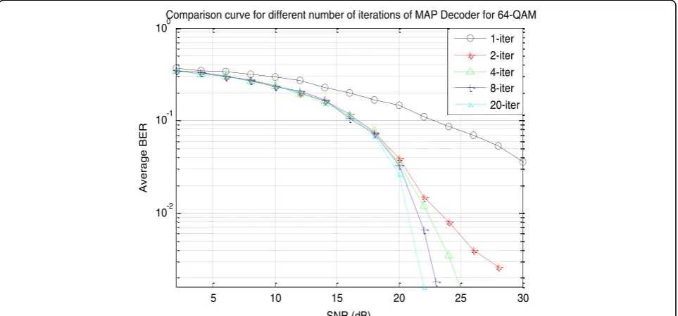
(WiMAX) has fixed seven iterations for the MAP de-coder. We have shown results in the section for 20, 8, 4, 2, and 1 number of iterations. The system shows a gen-eral trend of improvement in the performance as the iterations of MAP decoder are increased.
We have simulated the system for four different digital modulations: BPSK, QPSK, 16-QAM, and 64-QAM. OFDM symbol comprises of 256 subcarriers with GI length of 64.
5 10 15 20 25
10-3 10-2 10-1 100
SNR (dB)
Average BER
Comparison curve for different number of iterations of MAP Decoder for 16-QAM
1-iter
2-iter
4-iter
8-iter
20-iter
Figure 13Comparison curve of turbo-coded OFDM with PACE for 16-QAM modulation scheme for different number of iterations of MAP decoder.
5 10 15 20 25
10-3 10-2 10-1 100
SNR (dB)
Average BER
Comparison curve for different number of iterations of MAP Decoder for QPSK
1-iter
2-iter
4-iter
8-iter
20-iter
When compared with the curve given in Figure 9, BPSK shows a performance improvement of 4.9 dB for 20 itera-tions curve in Figure 11, which goes to the credit of using turbo codes in the proposed model. As discussed earlier, MAP decoding algorithm improves the system’s perform-ance by exchanging a soft decision among the two compo-nent map decoders. This performance improvement is depicted by a lowering of BER in these curves.
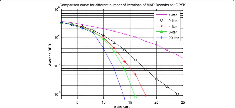
Similarly for QPSK, curves follow the same trend with the addition that performance improvement is more when compared with the curves in Figure 9. This is due to the fact that QPSK gains more from the application of turbo codes, compared to BPSK, because of the compact posi-tioning of signal points in constellation diagram as shown already in Figure 10. For four iterations, the QPSK curve given in Figure 12 shows a performance improvement of 3.1 dB at 10e-3 BER performance when compared with the study of [18]. This improvement is due to the efficient pilot tone insertion technique employed in our system that removes the possibility of interpolation error in the decoded bit as estimation of the channel is carried out at all subcarrier positions of OFDM symbol.
The comb-type PACE technique used in [18] has an in-herent interpolation error at the positions which are miss-ing with the pilot tones. It is because in the frequency-domain pilot-assisted block-type channel estimation strat-egy, some OFDM symbols of all the frames are dedicated for sending pilot data. All the subcarriers of these OFDM symbols carry pilot tones for estimating the channel im-pulse response. Contrary to it, in the frequency-domain pilot-assisted comb-type pilot insertion technique, some
subcarriers of all the OFDM symbols carry pilot data. For rest of the subcarrier locations which are missing with the pilot tones, a suitable interpolation technique, e.g., linear, cubic, spline, etc., is employed which calculates channel impulse response at the positions which are missing with the pilot tones. Because of the interpolation, comb-type PACE suffers with an inherent interpolation error which has been depicted by a 3.1-dB performance degradation when compared with the block-type PACE tested in our proposed model with turbo-coded OFDM system.
In Figures 13 and 14, the same parameters have been ap-plied, respectively, for 16-QAM and 64-QAM for measur-ing performance of the system. Again as we move towards the higher modulation schemes, there is a considerable gain in the performance improvement in the system. As dis-cussed earlier, it refers to the compact positioning of signal points in the constellation diagram which increase the chances of transmission errors. In the lower modulation schemes, the constellation points are already not in close proximity of each other so there are fewer chances for these points to merge and thus data corruption is also less likely to occur. The redundant bit added due to the application of turbo codes into such system appears to be just an extra consumption of energy. That’s why application to turbo codes is more significant for higher modulation schemes as compared to lower modulation schemes. Thus, there should be a compromise between the acceptable error rate for which the system is designed and the tolerable latency, for the choice of a particular modulation scheme, while implementing error correction into the system as all these parameters are directly linked with each other.
5 10 15 20 25 30
10-2 10-1 100
SNR (dB)
Average BER
Comparison curve for different number of iterations of MAP Decoder for 64-QAM
1-iter 2-iter 4-iter 8-iter 20-iter
Conclusions
In this article, we have proposed a novel error correction and ICI cancellation scheme for OFDM system. It mitigates the effect of ICI using the channel estimation matrix calcu-lated using pilot tones. Performance of the system is further improved under Rayleigh fading AWGN channel environ-ment using error correcting turbo codes which effectively improves BER of the system. Simulation results using dif-ferent modulation schemes show that the given algorithm
can significantly improve OFDM system’s performance
which is the physical layer implementation of MANETs.
Competing interests
The authors declare that they have no competing interests.
Acknowledgment
The authors are thankful to Higher Education Commission (HEC), Pakistan, which supported this study under the Program“HEC Indigenous Fellowships Scheme, Batch-IV”. The authors are also grateful to the reviewers who made constructive comments and gave their expert opinion to further improve the presentation of this article.
Received: 4 February 2012 Accepted: 17 September 2012 Published: 9 October 2012
References
1. H Dong, ID Chakeres, A. Gersho, EM Belding-Royer, JD Gibson, Selective bit-error checking at the MAC layer for voice over mobile ad hoc networks with IEEE 802.11, inIn Proceedings of IEEE Wireless Communications and
Networking Conference, 2nd edn. (Atlanta, GA, USA, 2004), pp. 1240–1245
2. M Zhao, ZShi, MC Reed, Iterative Turbo Channel Estimation for OFDM system over rapid dispersive fading channel. IEEE Transaction on Wireless Communication. 7(8), 3174–3184 (August 2008)
3. I Daniele Lo, R Marco, T Luigi Della, O Fabio, MIMO-OFDM physical layer real-time prototyping, inIn Proceedings of IEEE Wireless Communications and
Networking Conference(Las Vegas, USA, 2008), p. 18-23
4. C Berrou, A Glavieux, P Thitimajshima, Near Shannon limit error-correcting coding and decoding: turbo codes, inin Proceedings of IEEE International Conference on
Communications, ed. by, vol. 2 (Geneva, May 1993), pp. 1064–1070
5. HR Sadjadpour, Maximum a posteriori decoding algorithm for turbo codes,
inIn Proc. of SPIE, 4045th edn. (Orlando, FL, 2000), pp. 73–83
6. Y. Zhao, SG Haggman, Intercarrier interference self-cancellation scheme for OFDM mobile communication system. IEEE Trans. Commun.49(7), 1185–1191 (2001) 7. WG Jeon, KH Chang, YS Cho, An equalization technique for orthogonal
frequency-division multiplexing systems in time-variant multipath channels. IEEE Trans. Commun.47(1), 27–32 (1999)
8. P Chayratsami, MA Wickert, Channel estimation and mitigation techniques for OFDM in a Doppler spread channel, inIn Proceedings of IEEE Global
Communications Conference, ed. by (New Orleans, LA, USA, 2008), pp. 1–5
9. Y Li, LJ Cimini, NR Sollenberger, Robust channel estimation for OFDM systems with rapid dispersive fading channels. IEEE Trans. Commun.46(7), 902–915 (1998) 10. IA Chatzigeorgiou, MRD Rodrigues, IJ Wassell, RA Carrasco, A comparison of convolutional and turbo coding schemes for broadband FWA systems. IEEE Trans. Broadcast.53(2), 494–503 (2007)
11. J Martins, A Giulietti, M Strum, Performance comparison of convolutional and block turbo codes for WLAN applications, inIn Proceedings of 4thIEEE International
Conference on Devices, ed. by (Circuits and Systems, Aruba, 2002), pp. 1–5
12. J Ortín, P Gracia, F Gutiérrez, A Valdovinos, Performance analysis of turbo decoding algorithms in wireless OFDM systems. IEEE Trans. Consumer Electron.55(3), 1149–1154 (2009)
13. S Zeeshan, Y Syed-Abdur-Rehman, BM Inayatullah, WM Arif, Improved joint ICI cancellation and error correction for OFDM system, inIn Proceedings of 2011 International Conference on Electronic Commerce, Web Applications and
Communications, ed. by, vol. 1, 143rd edn. (Springer, Berlin, 2011), pp. 1–11
14. S Zeeshan, WM Arif, BM Inayatullah-Babar,OFDM, Turbo Codes and Improved
Channel Estimation—A Magical Combination(VDM Verilog Publishers,
Germany, 2011). ISBN: 9783639326505
15. B Sergio, B Ezio,Principles of Digital Transmission: With Wireless Applications, 1st edn. (Springer, New York, 1999)
16. V Branka, Y Jinhong, C Turbo,Principles and Applications(Kluwer Academic Publishers, London, 2002)
17. P Ramjee,OFDM for Wireless Communication Systems(Universal personal communication series, 2004)
18. S Elnoubi, S Elbadawy, C Shaban, Performance of turbo-coded OFDM system with comb pilot channel estimation in Rayleigh fading channel, inIn
Proceedings of IEEE Military Communications Conference, ed. by (San Diego
USA, 2008), pp. 1–6
doi:10.1186/1687-6180-2012-216
Cite this article as:Sabiret al.:Performance enhancement of wireless mobile adhoc networks through improved error correction and ICI cancellation.EURASIP Journal on Advances in Signal Processing2012
2012:216.
Submit your manuscript to a
journal and benefi t from:
7Convenient online submission
7Rigorous peer review
7Immediate publication on acceptance
7Open access: articles freely available online
7High visibility within the fi eld
7Retaining the copyright to your article