WYSE TECHNOLOGY 3040 North First Street San Jose, California 95134
Phone: 408-946-3075 TWX: 910-338-2251
The internal phosphor of the cathode ray tube is toxic. Use caution (safety goggles and gloves) whenever the cathode ray tube is handled. If the tube breaks exposing skin or eyes to the phosphor, rinse the affected area witl;1 cold water and con-sult a physician.
The terminal power cable is supplied with a safety ground. Do not use the terminal with an ungrounded outlet. Do not connect or disconnect the keyboard cable when the power is on.
DISCLAIMER
Wyse Technology makes no representations or warranties with respect to the contents of this Manual and disclaims any implied warranties or fitness for any particular application. Wyse Technology reserves the right to revise this Manual without obligation of Wyse Technology to notify any person or organization of such revision.
COPYRIGHT NOTICE
Copyright©1981 by Wyse Technology. All Rights Reserved Worldwide. No part of this publication may be reproduced without the express written permission of Wyse Technology.
WARNING: This equipment generates, uses, and can radiate radio frequency energy and if not installed and used in accordance with the in-struction manual, may cause interference to radio communications. It
SECflON 1. INTRODUCfION ... 1-1
SECTION 2. iNSTALLATION ... 2-1 2.1 Unpacking and Receiving Inspection ... 2-1 2.2 Site Preparation ... 2-1 2.3 Installation Verification ... 2-1 2.4 Interface Connectors Configuration. . . .. 2-2
SECfION 3. GENERAL DESCRIPTION. . . .. 3-1 3.1 Keyboard ... 3-1 3.2 DisplayFormat ... 3-1 3.3 Communication Modes ... 3-2 3.4 Data/Text Entry Facilities ... 3-2 3.5 SplitScreenModes ... 3-2 3.5.1 DisplayWindows ... 3-2 3.5.2 MemoryOrganization ... 3-5 3.5.3 External and Internal Scrolling ... 3-9 3.5.4 Internal Paging " ... " ... 3-9 3.6 Automatic Data Validation ... 3-9 3.7 AutomaticWord-Wrilpping ... 3-10 3.8 Special Form Control ... .- ... 3-10 3.9 Screen Enhancement Attribute ... 3-10 3.9.1 Special Display Enhancement ... 3-10
SECTION 4. 4.1 4.2 4.3 4.3.1. 4.3.2. 4.4 4.4.1. 4.4.2 4.4.3 4.4.4 4.4.5 4.4.6 4.4.7 4.4.8 4.4.9 4.4.10 4.4.11 4.4.12 4.4.13 4.5 4.5.1 4.5.2 4.5.3 4.5.4 4.5.5 4.5.6 4.5.7
4.5.9 4.5.10 4.5.11 4.5.12 4.6 4.6.1 4.6.2 4.6.3 4.6.4 4.6.5 4.6.6 4.6.7 4.6.8 4.7 4.8 4.8.1 4.9 4.9.1 4.9.2 4.10 4.11 4.12 4.12.1 4.12.2 4.13 4.13.1 4.14 SECTION 5. 5.1 5.2 5.2.1 5.2.2 5.2.3 5.2.4 5.2.5 5.2.6 5.2.7 5.2.8 5.2.9 5.2.10 5.2.11 5.2.12 5.2.13 5.2.14 5.2.15 5.2.16 5.2.17 5.2.18 5.2.19 5.3 SECTION 6.
INS/REP (unshifted) . . . .. 4-4 INS/REP (shifted) ... . . . .. 4-4 SCRN EDIT (unshifted). . . .. 4-5 SCRN EDIT (shifted) ... 4-5 Block Transmission Keys . . .. . . .. 4-5 SEND LINE (unshifted). . . .. 4-5 SEND LINE (shifted) ... ". . . . .. 4-5 SEND PAGE (unshifted) ... 4-5 SEND PAGE (shifted) ...•... 4-5 SOM/EOM (unshifted) . . . .. 4-5 SOM/EOM (shifted) ... 4-6 SEND MSG (unshifted) . . . .. 4-6 SEND MSG (shifted) ... . . . .. 4-6 BREAK Key ... 4-6 Programmable Function Keys ... " .. ". . . . .. 4-6 FUNCT ... 4-6 Local Print Keys .... . . .. 4-6 PRINT(unshifted) ... 4-6 PRIN'J(shifted) ... 4-6 SCRLUp ... " ... 4-6 SCRL Down ... 4-7 PAGEKey ... 4-7 Internal Paging . . . .. 4-7 Split Display Window Selection. . . .. 4-7 RESET (unshif ted) ... 4-7 RESET (shif ted) ... 4-7 Key-click Control . . . .. 4-7
COMMUNICATION CONTROL. . . ..
5-1
ASCII Control Codes ... ~ . . . .. 5-1 ESCape Sequences ... 5-1 Cursor Set/Read . . . .. 5-1 Keyboard Lock/Unlock. . . .. 5-2 Communication Modes Controls ... 5-2 Text Editing Modes Controls ... 5-2 Protect Form Controls ... 5-2 Special Cursor Controls . . . .. 5-2 Column Tabulation Controls. . . .. 5-3 Data/Text Editing Controls ... ~ ... 5-3 Scrolling and Paging Controls . . . • . . . .. 5-3 Screen Attributes and Graphics ... 5-3 Message Fields and Labeling Fields. . . .. 5-3 Display Mode Selection ... 5-4 Split Segment Selection. . . .. 5-4 Vertical Split Column . . . .. 5-4 Block Transmission ... " ... "5-4 Local Print Controls ... 5-5 Programming the Function Keys. . . .. 5-5 Two Character Function Key Sequences andModified Cursor Up Key ... 5-5 Read Cursor Byte ... : . . . .. 5-5 Remote Computer Handshaking Protocol. . . .. 5-6
APPENDIX B. TOP MESSAGE FIELD LINE AND BOTTOM FUNCTION KEY LABELING LINE ... B-1
TABLES TABLE 1. TABLE 2. TABLE 3. TABLE 4. TABLE 5. TABLE 6. TABLE 7. TABLE 8. TABLE 9. TABLE 10.
Terminal Control Codes ... T-l ASCIICodes ... : ... T-2 Default Function Key Code. . . .. . . .. T-2 GraphicCodes ... T-3 CursorRoworColumnCode ... T-3 Screen Attribute Codes ... T-4 VerticalSplitColumn40SeparationCode ... T-5 Display Mode Selection . . . .. . . .. T -6 Terminal Escape Sequences. . . • . . . .. T-6 Keyboard Command Code Sequences . . . .. T-7
LIST OF ILLUSTRATIONS Figure 1-1.
Figure 2-1. Figure 2-2. Figure 2-3 Figure 3-1. Figure 3-2. Figure 3-3. Figure 3-4. Figure 3-5. Figure 3-6. Figure 4-1.
This manual is designed to aid the users in installing, operating, and programming the terminal. The manual is divided into sections based on these functions. The following paragraphs give a brief description of the scope of the sections.
Section 1 - Specifications
This section contains the introduction and product specifications. Section 2 - Installation
This section contains detailed information on the receiving, unpacking, site preparation, and installation procedures for operating the terminal.
Section 3 - General Description
This section describes the terminal, its features and applications. Section 4 - Keyboard
This section contains detailed information about the keyboard, its layout and the use of the alphanumeric keys, cursor control keys and function keys.
Section S - Communication Control
This section contains specific information on the use of the command sequences. Section 6 - Terminal Self-Test Facilities
This section provides information on procedures for trouble-shooting terminal problems. Additionally, there are appendices covering the various codes available in the terminal as well as a listing of the tables and illustrations in the manual.
1-1
FIGURE 1.1 Power
Standard Optional Dimensions
Shipping Weight Finish
Keyboard
CRT
Display attributes Display format
Character Matrix Character set Memory Capacity
Communication Type
Baud Rates
Data size Stop bits Parity
Operating temperature Storage temperature Humidity
Altitude
SPECIFICATIONS
120 VAC 60 Hz, 60 watts (20S BTU/hour) approximately
2201240 VAC SO Hz, 60 watts (20S BTU/hour) approximately Keyboard - 2.6"H x 20.S"W x 7.1"D (6.604cm x 52.07 cm x IS'.034cm) Display Cabinet - 12.5"H x 15"W x 12.5" D (31.75cm x 38.1 cm x
31.75cm) 38 lbs. (17.24kg) approximately Beige and black
Detachable with 6' (l.8288m) coiled cable lOS keys, cursor control pad, numeric pad, and function keys
12" (30.48cm) diagonal with non-glare display
Dim, reverse, underscore, blink, blank, and combinations
24 rows x 80 characters per row plus two rows for message and function key identification
8 x 10 matrix in a 10 x 11 cell
128 characters with graphics (96 displayable ASCII and 32 control codes) 1 page (supports 1920 characters); 2 page optional (supports 3840 characters)
EIA RS-232C standard 20 MA current loop optional
50,75,110,134.5,150,300,600,1200,1800,2000,2400,3600,4800, 7200,9600
7 or 8 bits 1 or 2 stop bits
Odd, even, mark or space 32° - 122°F (0° - SO°C)
- 40° -
+
140°F ( - 40° -+
60°C)SECTION 2. INSTALLATION
2.1 UNPACKING AND RECEIVING INSPECTION
Each terminal is shipped in one container which encloses the display unit, keyboard, pedestal base, power cable, and the Terminal Reference Manual. The terminal is enclosed with preformed styrofoam inserts designed to provide maximum protection during shipping.
After receiving the terminal, the shipping containers should be inspected carefully for damage. All external damage should be noted on the waybill and should be acknowledged by the delivery agent. A written report should be given to the transfer company or carrier. If there is no external damage to the containers, unpack the terminals and inspect for inter-nal damage.
Sharp instruments should NOT be used to open the container. Remove the terminal carefully and inspect it thoroughly for damage such as loose modules or components. If any damage exists, notify the transfer company immediately. The company is not responsible for shipping damage. Any repairs made for damages which occurred during shipping are billable to the customer. All packaging materials should be saved for possible future use in reshipping the terminal.
2.2 SITE PREPARATION
The' terminal has been specially designed to conform to most office environments. A table or desk with a nearby three pronged electric outlet supplying the required power (110 VAC 60 Hz or 220 VAC 50 Hz) and a communication interface located in the vicinity are sufficient to set up the terminal. Additional surface space is necessary if a local printer is also required.
2.3 INSTALLATION VERIFICATION
The terminal onl off rotary switch in the front should be in the fully counter clock-wise or off position before the terminal is plugged into the outlet. The following list should be checked before turning on the terminal:
I. Communication and printer cables are installed properly?
2. Power cable correctly plugged in? (Check serial # tag on back panel for ItO VAC or 220 VAC.) 3. Keyboard cable is secured?
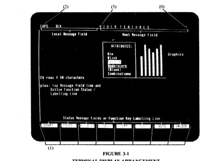
4. Switch settings all correct? Baud rate? Parity? Stop bits? 50/60Hz? Communication mode? Blink cursor? lor 2 pages? (See Figure 2-3 and Appendix A.)
Note: SWI switch settings cannot be all OFF (see Section 6).
2.4 INTERFACE CONNECTORS CONFIGURATION
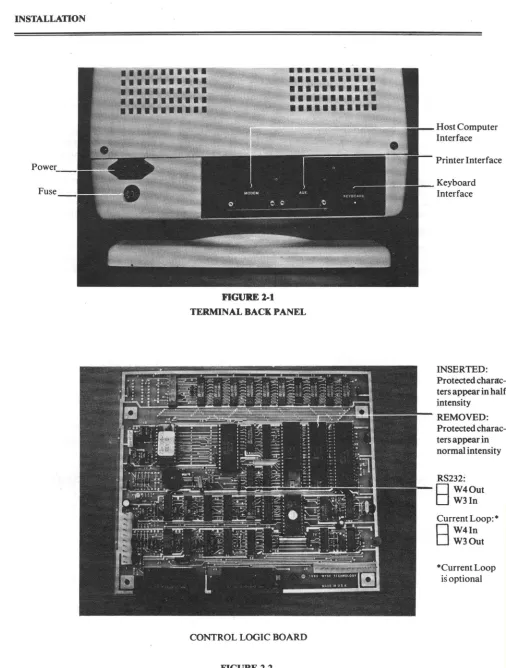
There are two communication interface connectors on the terminal. Facing the terminal from the back, the connector on the left is for communicating with the host computer and the connector on the right is for sending data to the local printer (see Figure 2-1). Their configurations are as follows:
Host Computer Interface Connector Configuration:
RS-232 C SIGNALS: PRINTER INTERFACE CONNECTOR CONFIGURATION:
PIN # SIGNAL PIN # SIGNAL
1 Frame ground
2 Transmit Data (output) 3 Receive Data (input)
1
Request To Send (output).) Clear To Send (input)
7 Signal Ground
8 Data Carrier Detect (input) 20 Data Terminal Ready (output) CURRENT LOOP SIGNALS:·
PIN # SIGNAL
7
9 10
11
12
13 14
Signal ground
470-ohm resistor to
+
12 volts Receive data 1 (input) Receive data 2 (input) Transmit data I (output) Transmit data 2 (output) 270-ohm resistor to+
12 volts1 Frame ground
3 Transmit Data (output to printer)
7 Signal ground
20 Printer ready (input from printer)
·Notes on current loop operation:
I. Receive data I and 2 and Transmit data land 2 are not polarity specific, i.e., they are interchangeable.
2. The 270-0hm resistors in conjunction with the signal ground can be used to provide active current sources for the current loop.
3. Both receive and transmit signa~ are opto-isolated, and can withstand ± 750 volts with respect to signal ground.
Fuse
2-2
.
. .
--~--~---.
.
,...
...
.-
-
--•••••••••••
•
••••••••••
•••••••••••
•
••
•
••••••••
•••••••••••
•
••••••••••
•••••••••••
•
••••••••••
FIGURE 1-1
TERNnNAL BACK PANEL
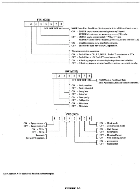
OONTROLLOGICBOARD
FIGURE 1-1
INTERNAL JUMPER CONNECTION
Host Computer Interface
Printer Interface
Keyboard Interface
INSERTED: Protected charac-ters appear in half intensity
REMOVED: Protected charac-ters appear in normal intensity
RS232:
o
W40utD
W3In Current Loop:·8
W4In W30ut9600 Printer Port Baud Rate (See Appendix A for additional baud rates.) ON - ENTER key to operate as carriage return (CR) and
RETURN key to operate as carriage return (CR) only. OFF - ENTER key to operate as tab (TAB or HT) and
RETURN key to operate as carriage return (CR) and line feed (LF) ON - Disables the auto-new-line(NL) operation.
OFF - Enables the auto-new-line (NL) operation. Block transmission sequences:
ON - Endofline = CR, LF, NULL, EndofTransmission = ETX OFF - End of line = US, End of Transmission = CR
ON - All editing keys are set up as duplex keys (host controllable) OFF - All editing keys are set up as local keys and are executable locally.
OFF OFF OFF ON ---{ 9600 Modem Port Baud Rate ON . Parity enabled
OFF - Parity disabled ON -2 stop bits OFF - I stop bit
----I[
Ot, - Even parityOFF - Odd parity
(See Appendix A for additional baud rates.)
'---i[
ON - 8 bits data OFF -7 bits dataON - 2 page memory OFF - I page memory ON - 50HZ]
OFF - 60 Hz - - - ' Reserved.
Set to OFF position.
See Appendix A for additional details & some examples.
FIGURE 2-3 SWITCH SETTINGS
ON - Block mode OFF - Conversation mode ON - Half Duplex OFF - Full Duplex OFF - Blinking Cursor ON - Non-blinkingcursor ON - green screen OFF -black screen
SECTION 3. GENERAL DESCRIPTION
The display terminal consists of a detached keyboard, a CRT display, internal microprocessor controlled video and logic, a communication interface, and a local printer interface. It allows the user full control in entering data/text onto the dis-play and in communicating information with a host computer. Disdis-played data/text can be printed on a local printer via the standard local printer interface.
3.1 KEYBOARD
The keyboard resembles a conventional typewriter with additional keys for local editing and remote communication with a computer. When used in combination with other keys, many of these keys can control several operations. The !05-key detachable keyboard is organized into four sections (see Table 4-1):
- the alphanumeric section - the cursor control section - the numeric data entry section
- the local editing and remote function section
3.2 DISPLAY FORMAT
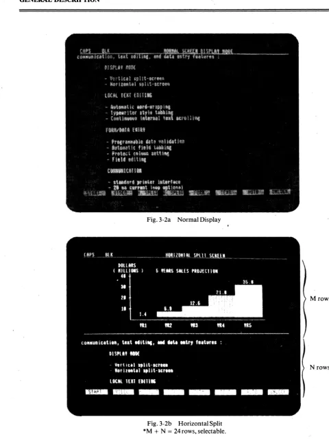
The terminal screen is organized into 24 rows of 80 characters each plus two rows for message and function key identifica-tion (see Figure 3-1).
FIGURE 3-1
n;RMINAL DISPLAY ARRANGEMENT
The display contains 4 special display attributes which can be ~~t in any combinations (see ESC A sequence in Section 5.2.10). Their relative positions on the screen are highlighted by (0), (I), (2), and (3). These special attributes are as follows: (0) Data/Text Entry Area start attribute.
(I) Function Key Labeling Line Field separation attribute. (2) Local Message Field start attribute.
(3) Host Message Field start attribute.
The bottom row consists of 8 labeling fields which can be used to display function key descriptions or any other status messages. The 8 labeling fields can also be used contiguously as one message field line. This row is the Function Key Labeling Line (see Appendix B).
The top row consists of two message fields and is called the Message Field Line. The two message fields are the Local Message field and the Host Message Field (see Appendix B).
The middle 24 rows of the display compose the data/text entry area which is the normal work space for the operator. This area is used to display data entered by the operator or data received from the host computer.
The terminal is capable of storing up to 48 rows of~O characters each, a total of 3840 characters. The data/text entry area can be programmed in either normal, horizontal or vertical split screen display format for displaying the internal text storage (see Section 3.5).
Special display attributes can be used to enhance the Local Message Field, the Host Message Field, the Function Key Labeling Line and the data/text entry area. These enhancement attributes can be used to set up special effects on the screen (such as a reverse and underscored data/text entry area), or they can be used to hide a certain portion of the screen (such as the Local Message Field) from the operator (see Section 3.9).
3.3 COMMUNICATION MODES
The terminal can operate in one of three different communication modes: block, half duplex or full duplex conversation (or TTY mode).
Under block mode, text entry and editing are locally conducted to reduce the host computer overhead and communica-tion line (e.g. phone line) hook-up time. No transmission to the computer is effected except when the break key, the func-tion keys, or anyone of the 'SEND' keys are depressed.
Under half duplex conversation mode, each character entered is sent to the host computer and displayed. Control keys are acted upon and are simultaneously sent to the computer. Local editing keys (e.g. DEL CHAR) are executed and their corresponding command sequence (ESC sequence) can be sent to the host computer if desirt-d (see Appendix A and Table 10).
Under full duplex conversation mode, each character or control key entered is sent to the host computer but is not acted upon locally.
A monitor submode is available for the display and transmission of non-text! control codes to and from the host computer (see Section 5.2.3).
3.4 DATA TEXT ENTRY FACILITIES
F or data entry applications, the terminal can be programmed so that fields of data can either be unprotected or protected. For example, the terminal can operate in a protect mode where only unprotected fields are accessible by the terminal operator. Special commands and line graphics capability are.also provided to establish data entry 'forms' on the screen. The terminal also provides the user with a comprehensive set of text editing features:
- Character replace, insert, or delete - Line delete or insert
- Clear partial line or text body - Typewriter style column tabbing
In addition, the terminal provides the user with two advanced features which are normally available only in high-end terminals:
- Programmable local data entry validation to reduce computer overhead in checking for erroneous data, (requires second page option).
~ Automatic word-wrapping to facilitate text generation. Terminal user does not have to worry about carriage return/line feed in the course of data entry.
3.5 SPLIT-SCREEN MODES
The terminal supports various display modes. The following sections describe their formats and memory organization.
3.5.1. DISPLAY WINDOWS
The terminal can be programmed by the user or host computer to operate in one of four different display formats (Figures 3-2a, 3-2b, 3-2c, 3-2d):
3-3
Fig.3-2a Normal Display
Fig. 3-2b Horizontal Split *M
+
N = 24 rows, selectable.FIGURE 3-2
TERMINAL DISPLAY WINDOWS' FORMATS
Mrows
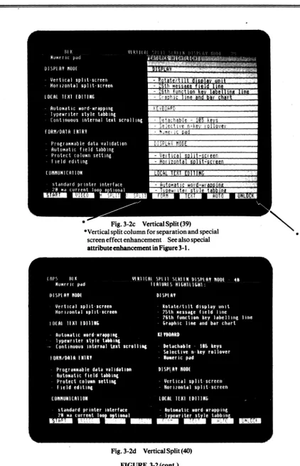
Fig.3-2c Vertical Split (39)
·Vertical split column for separation and special screen effect enhancement .. See also special attribute enhancement in Figure 3-1.
Fig.3-2d Vertical Split (40)
FIGURE 3-2 (cont.)
TERMINAL DISPLAY WINDOWS FORMATS
•
1. Normal display window of 24 rows of 80 characters each
2. Horizontal split-screen format with upper and lower display windows organized into: Upper window: M rows X 80 characters
Lower window: N rows X 80 characters
where M can be programmed to be any number from 1 to 24, N can be programmed to be any number from 0 to 23, and M
+
N = 24 (see Table 8).3. Vertical split-screen format with left and right display windows organized into: Left window: 24 rows X 39 characters
Right window: 24 rows X 39 characters
4. Vertical split-screen format with left and right display windows organized into: Left window: 24 rows X 40 characters
Right window: 24 rows X 40 characters
These display formats can be selected by command sequences from the keyboard or the host computer (see Section 4.12.2). The 'Normal' display format is similar to most conventional terminals supporting only one text segment inter-nally in the terminaL
The split display formats support two text segments simultaneously in the terminal. However, only one display window can be selected to be active at one time either by the local shifted 'PAGE' key or by special 'ESCAPE' sequences from the host computer.
The active display window is identified by the current screen cursor position. All data/text editing and communication operations are performed on the active display window only. The inactive window is not affected.
Under the vertical split-screen format with text segments organized into 39 character columns there is a separation col-umn at colcol-umns 40 and 80 ofthe screen which can be used to separate the two split windows. In addition to the default ver-tical separation line, screen effect attributes can also be used to highlight the two split windows(see Sections3.9.1 and 5.2.14 on setting the vertical split column).
3.5.2 MEMORY ORGANIZATION
The terminal supports an internal display memory of either 1920 characters (standard) or 3840 characters (optional). Together with the 4 display window formats described previously, the terminal display memory can be programmed into 8 different storage formats (see Section 5.2.12).
In the 'normal' display format, the internal display memory is organized as one contiguous text segment. In any of the split-screen formats, the display memory is organized as 2 text segments, namely segment 0 and segment 1:
DISPLAY MODE SELECTION MEMORY STORAGE SEGMENT DISPLAY W~NDOW
Horizontal Split:
Vertical Split:
Split Segment 0 Split Segment 1 Split Segment 0 Split Segment 1
Upper display window Lower display window Left display window Right display window
If the terminal supports a 1920 character display memory, each text segment is equal in size to its corresponding display window. However, when the terminal supports 3840 characters of display memory, all text segments except that of Split Segment 0 of the horizontal split are larger in size than their corresponding display windows. Internal scrolling and pag-ing capabilities are provided to position the desired portion of the text segment within the display window (see Figures 3-3,3-4, 3-5).
Only one text segment is active at a time. The cursor location identifies the active text segment. All keyboard anti com-munication functions in subsequent sections apply only to the active text segment. The following notations will be used frequently in the subsequent discussion about cursor movement:
3-5
Start-of-text: the first character in the text.
Start-of-text row: thefirst row o/characters in the text.
End-of-text: the last character in the text.
End-of-text row: the last row of characters in the text.
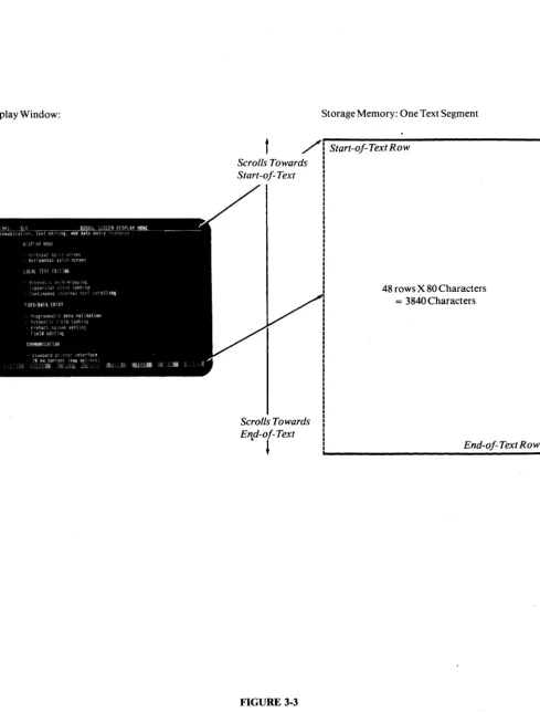
Display Window:
t
Scrolls Towards Start-of- Text
Scrolls Towards End-of- Text
. l
FIGURE 3-3
Storage Memory: One Text Segment
Start-of- Text Row
48 rows X 80 Characters
= 3840 Characters
End-of- Text Row
NORMAL DISPLAY MODE WITH 3840 CHARACTERS STORAGE MEMORY
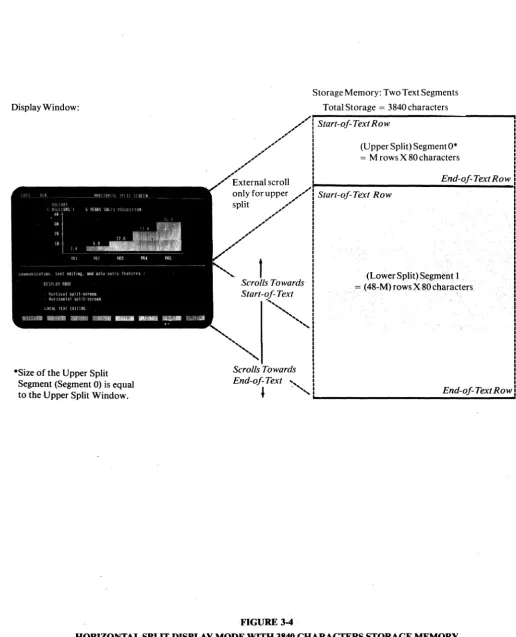
Display Window:
·Size of the Upper Split Segment (Segment 0) is equal to the Upper Split Window.
t
Scrolls Towards Start-of- Text'""
"',
Storage Memory: Two Text Segments Total Storage = 3840 characters Start-of- Text Row
(Upper Split) Segment O·
= M rows X 80 characters
End-of-TextRow
Start-of- Text Row
Scrolls Towards End-of- Text
"-, . -... End-of-TextRow
---FIGURE 3-4
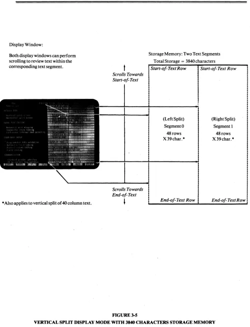
Display Window:
Both display windows can perform scrolling to review text within the corresponding text segment.
* Also applies to vertical split of 40 column text.
t
Scrolls rowards Start-oJ- Text
Scrolls Towards End-oJ- Text
,
FIGURE 3-5
Storage Memory: Two Text Segments Total Storage = 3840 characters
Start-oJ-TextRow Start-oj-Text Row
(Left Split) Segment 0 48 rows X39char.*
End-oJ- Text Row
(Right Split) Segment I
48 rows X 39 char. *
End-oJ- Text Row
3.5.3. EXTERNAL AND INTERNAL SCROLLING
The terminal supports two types of scrolling operations:
When the data entered passes the bottom or last row ofthe display window (i.e.; the 24th row ofthe 'Normal' display win-dow or the 'M'th row of the upper display winwin-dow under the horizontal split format), the display winwin-dow scrolls up.
If the bottom row of the display window corresponds to the end-of-text row, the scrolling operation causes the loss of the start-of-text row. This kind of scrolling action is defined as external scrolling because it is usually activated during com-munication with the host computer.
External scrolling is prohibited when the terminal is in the PROTECT, EDIT, or data validation submode. (Note: these are normally local operating modes). If the data entered passes the end-of-text row, the cursor is positioned to the start-of-text row.
If the bottom row of the display window does not cQrr.espond to the end-of-text row, the display window scrolls up one row to review the immediately following data line. There is no data lost under this kind of scrolling operation and hence is defined as internal scrolling.
Internal scrolling applies only if the size of the display window is smaller than the size of its corresponding text segment and is normally used for local editing and text viewing.
3.5.4. INTERNAL PAGING
The terminal provides the user with an internal paging mechanism which forces the display window to scroll up or down the text segment a number of rows equal to that of the display window. For example, if the display window supports 12 rows of text, the display window scrolls through 12 rows of text with one internal paging operation.
3.6 AUTOMATIC DATA VALIDATION
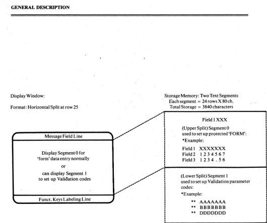
The automatic data validation feature is provided by the terminal to perform local error checking of operator inputs under block mode. Using this feature can substantially reduce host computer overhead. To use the data validation feature, the second page option is required.
The data validation feature is initiated by the ESC<sequence. Once initiated, the terminal internal memory is split into two equal text segments of 24 rows of 80 characters each as if the following horizontal split mode command had been issued:
sequence: ESC x 5 8 (see the ACTION OF CHANGING DISPLAY MODE for ESC x, Section 5.2.12) The two split segments are used as a foreground 'form' and background storage for the validation parameters.
Split segment 0 is used to build the data entry 'form' with protected and unprotected fields and split segment 1 is used to set up the validation parameters. Each character position in segment 0 corresponds to a character position in segment 1 in the same row/column position, i.e. the character in row 2 column 18 in segment 1 contains the data entry validation· parameters for the character position in row 2 column 18 of segment 0 (Figure 3-6). The validation parameters set up in segment 1 can be entered by activating segment 1 and then entering as any normal data. The parameters can be:
space - any key code is acceptable, or A - alphabet only, or
B - numeric only, or
D - numeric plus special characters including:
+ .
* / ( ) ,
It should be noted that data validation can be applied only to the data entry area or the unprotectedjields and that the data validation check applies only to keyboard entries.
External·scrolling is disabled when this mode is activated. The split screen selection key (the shifted PAGE key) is ignored to protect the validation parameters stored in segment 1. The following steps should be used to activate the data valida-tion mode:
3-9
1. Turn on data validation mode with ESC< (The host computer should wait for acknowledgement (ACK) from the terminal for the completion of the set-up operation of the data validation mode before going to step 2).
2. Place the terminal into block mode.
4. Activate segment 1 with ESC} and set up the validation parameters. The data/text entry area can be 'hidden' with the ESC A 0 3 sequence prior to setting up the parameters so that the operator will not see the validation parameters as they are entered onto the screen.
5. Activate segment 0 with ESC ], turn on the data/text entry area with ESC A 0 0 and then set up the protected 'form' on segment O.
6. Turn on protect mode with ESC & and unlock the keyboard with ESC" for data entry. Note: For subsequent setups, only steps 3 through 6 are necessary.
3.7 AUTOMATIC WORD-WRAPPING
The word-wrapping feature is activated under the EDIT mode and only affects keyboard entries. When text is entered at the end of a row (i.e. the 80th, 39th, or 40th column, !epending on the selected display mode), the word-wrapping opera-tion is initiated. A 'line-break' posiopera-tion is determined by backtracking from the end of the row. The 'line-break' posiopera-tion is defined as the character immediately after any non-alphabet character or protected character. Characters starting from the 'line-break' position to the end of the row are moved to the beginning of the next row. The cursor is placed to the right of the last character position of the wrapped characters. Any character positions at the beginning of the next row will be overwritten. If the insert mode is on the wrap characters will be inserted instead. The word-wrapping feature should be used only during block mode.
3.8 SPECIAL FORM CONTROL
A command sequence which allows all unprotect positions to be written with a specified code:
ESC. Code
For example, if code = A, then all the unprotected positions are written with 'A's.
This command sequence is very useful in data entry application. One example is an application which requires all un-protected positions to be written with underline symbols so that the operator can visualize the exact size of a data field. Upon completion of sending all the entered data to the host computer, the host computer can send an 'ESC. _' sequence to reset all unprotected positions with underline symbols. This enhances the speed in transaction oriented systems. Another command sequence allows all unprotected positions to be written with a specified attribute code:
ESC ! ATTR
where ATTR is any attribute code which is specified for the ESC G attribute generation sequence (see Table 6). This com-mand sequence is provided for the generation of forms which require attribute enhancements. The following are two ex-amples where this sequence applies:
1. The entire screen can be written with 'normal' attribute codes before a form is generated. By doing this, it eliminates the 'flashing' effect which occurs in most terminals when a form is being generated. 2. If a form is composed of primarily one kind of attribute for its fields, this sequence can reduce the
time and code required by presetting the screen with the required attribute.
3.9 SCREEN ENHANCEMENT ATTRIBUTES
The terminal provides five screen enhancement attributes: dim (or half intensity), reverse, underscore, blink, and blank (no show). These attributes can be used selectively in any combination to highlight data fields and text blocks. The code that generates these screen enhancement attributes occupies one screen position and is displayed as a 'blank'. It enhances the displaying of all character positions to the right and subsequent rows until the next screen attribute is encountered (see Section 5.2.10).
The terminal also supports a 'dim' or half intensity enhancement attribute which does not occupy any screen position. Characters generated under the write protect mode are displayed in half intensity and the enhancement affects the display on a character by character basis. This dim attribute can be turned off if desired (see Figure 2-2).
3.9.1 SPECIAL SCREEN DISPLAY ENHANCEMENT
In addition to enhancing data or text with screen enhancement attributes, the terminal provides special screen enhance-ment attributes for different screen appearances (see Section 3.2 and Figure 3-1). These 4 special screen attributes can be set up by the ESC A command sequence and they are (see Section 5.2.10):
Display Window:
Format: Horizontal Split at row 25
Message Field Line
Display Segment 0 for 'form' data entry normally
or
can display Segment 1 to set up Validation codes
Funct. Keys Labeling Line
Storage Memory: Two Text Segments
Each segment
=
24rowsX80ch.Total Storage = 3840 characters
... /'""1
.... I .... I .... I .... I .... I
/"",
i
.... I ... I
.. '
I
I
I I
I
Field 1 XXX (Upper Split) Segment 0
used to set up protected 'FORM': *Example:
Field 1 XXXXXXX
Field 2 1 2 3 4 5 6 7
Field 3 1 2 3 4 . 5 6
I
....
I~---~
....
' " ,..
....
....
..
'
..
'..
'..
',
..
'....
(Lower Split) Segment 1
used to set up Validation parameter codes:
*Example:
** AAAAAAA ** BBBBBBB ** DDDDDDD
*The field data validation feature requires the terminal internal storage to be arranged under the horizontal split display format so that the 3840 characters storage memory are split into two equal segments of 24 rows X 80 characters each. The protected form is set up in segment 0 and the validation codes are set up in segment 1 in a one character to one validation code basis at the same row Icolumn coordinate. This example shows that field I is an alphabet field and field 2 is a numeric field only.
**Validation code is as follows:
space any keyin accepted
A = alphabet only B
=
numeric only D = numeric,.+
* I ( or)FIGURE 3-6
TERMINAL FIELD DATA VALIDATION ARRANGEMENT
2. The function key labeling line attribute which is at the start and end of each function key labeling field.
Example: ESC A J t Creates reverse and dim labeling fields.
3. The local message field attribute which is at the start of the message field line. Example: ESC A 2 J Blanks the local message field.
4. The host message field attribute which is at the start of the host message field. Example: ESC A 3 2 Blinks the host message field.
Upon power up, these attributes are set up as follows:
I. The data/text entry attribute is set to normal or reverse depending on the green/black screen selection (see Appendix A).
2. The function key labeling field attribute is set to 'dim' or half intensity. 3. The local;message field attribute is set to underscore.
4. The host message field attribute is set to a space character.
A column of attribute codes can be written into column 40 of the active display window. This screen enhancement feature allows the two split windows of the vertical split screen display mode (39) to be highlighted. The following shows how it can be implemented:
I. The left split window can be highlighted with the attribute ATTR by the following step: a. ESC] To activate the left split window.
b. ESC n 0 To enter at column 40 of the screen with a column of 'normal' display
c. ESC} d.ESCnAITR
attributes.
To activate the right split window.
To set at column 80 of the screen (column 40 of the active split window) with a column of attribute codes designated by ATTR (see Table 6).
e. ESC A 0 AITR To set the top row of the left split window with attribute enhancement ATTR. 2. The right split window can be highlighted with attribute ATTR by the following steps:
a. ESC} To activate the right split window.
b. ESC n 0 To enter at column 80 of the screen with a column of 'normal' display
attrib-c. ESC] d. ESC nAITR
utes.
To activate the left split window.
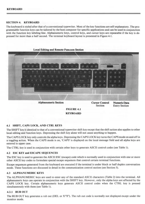
SECTION 4. KEYBOARD
The keyboard is styled after that of a conventional typewriter. Most of the key functions are self-explanatory. The pro-grammable function keys can be t'ailored by the 'host .computer for specific applications and can be used in conjunction with the function key labeling line. Alphanumeric keys, control keys, and cursor keys are repeatable if the key is de-pressed for more than a half second. The terminal keyboard layout is presented in Figure 4-1.
Local Editing and Remote Fun,,-uon Section
Alphanumeric Section
4.1 SHIFf, CAPS LOCK, AND CTRL KEYS
FIGURE 4.1 KEYBOARD
Cursor Control
Section
Numeric Data
Entry Section
The SHIFT key is identical to that of a conventional typewriter shift key except that the shift action also applies to other local editing and function keys. Depressing the shift key alone will not cause anything to happen.
The CAPS LOCK key only controls the alpha keys. Depressing the CAPS LOCK key turns the CAPS mode on and off in a toggling action. When the CAPS mode is on, 'CAPS' is displayed on the local message field and all alpha keys are entered in upper case.
The CTRL key is used in conjunction with certain other keys to generate ASCII control codes (see Table I).
4.2 ESC KEY and ESCAPE SEQUENCES
The ESC key is used to generate the ASCII ESC (escape) code which is normally used in conjunction with one or more other ASCII key codes to formulate special escape sequences that control certain terminal functions.
Escape sequences generated from the keyboard are executed if the terminal is under block or half duplex conversation mode. These functions are discussed in detail in the communication control section (see Section 5).
4.3 ALPHANUMERIC KEYS
The ALPHANUMERIC keys are used to enter any of the standard ASCII characters (Table 2) into the terminal. All alphanumeric keys can operate in conjunction with the SHIFT key. However, only the alpha keys are affected by the CAPS LOCK key. Certain alphanumeric keys generate ASCII control codes when the CTRL key is pressed simultaneously with them (see Table I).
4.3.1 RUB OUT
The RUB OUT key generates a rub out (DEL or X'7F'). The rub out code is normally not displayed except under the
monitor mode.
4.3.2. NUMERIC KEY PAD and ENTER KEY
The numeric key pad is used mainly for convenience in data entry. The '-', '.', and ',' keys generate ASCII equivalent codes. The ENTER key isswitch selectable to generate either a RETURN key or a TAB key. With the shift key depressed, the ENTER key turns the key-click on/off.
4.4. CURSOR CONTROL KEYS
The cursor indicates the next position available on the screen for data entry. It can be switch s.electable to be either a blink-ing or non-blinkblink-ing rectangular block. (See Appendix A). As characters are entered the cursor moves from left to right across the display. The cursor automatically moves to the beginning of the row immediately below when it reaches the end of a row. Scrolling may occur when the cursor reaches the bottom row of the display window. Cursor movement can be controlled either by the operator or the computer.
The cursor skips all protected data on the screen if the protect mode is on:
- If cursor movement is towards the right of the screen, the cursor skips all protected positions until it reaches the first unprotected position to the right. In some cases, the cursor may have to skip several rows of protected data before
'landing' on an unprotected position. .
- If cursor movement is towards the left of the screen, the cursor skips all protected positions until it reaches the first unprotected position to the left. In some cases, the cursor may have to skip several rows of protected data before 'land-ing' on an unprotected position.
- If cursor movement is towards the bottom of the screen and a protected position is immediately below the original cursor position, the cursor moves to the right of the protected position in its search for the next unprotected position. - If cursor movement is towards the top of the screen and a protected position is immediately above the original cursor
position, the cursor moves to the left of the protected position in its search for the next unprotected position. Command code sequences generated by cursor control keys are outlined in Table 10.
4.4.1 HOME
When unshifted, this key moves the cursor to the first character position at the upper left hand corner of the display window.
When shifted, this key moves the cursor to the first character position ofthe text segment or the start-of-text. The shifted HOME key forces the display window to display the start-of-text. In either case, the cursor moves to the first unprotected position at the upper left corner of the display window.
4.4.2 CURSOR RIGHT
This key moves the cursor one character position to the right. When the cursor reaches the lower right hand corner of the display window scrolling occurs. When the cursor reaches the end-of-text and the terminal is not in the EDIT, protect or data validation modes, external scrolling occurs. That is, data is scrolled offthe screen and internal memory; therefore, it is subsequently lost.
If the protect mode is on, the cursor moves right to the first unprotected position. When the cursor reaches the end-of-text and when the terminal is in the EDIT, protect, or data validation modes, the cursor moves to the start-of-text of the cur-rent text segment. If the start-of-text is not currently displayed, this forces the terminal to display the start-of-text.
4.4.3 CURSOR LEFT
This key moves the cursor one character position to the left. When the cursor reaches the upper left hand corner of the display window scrolling occurs.
If the protect mode is on, the cursor moves leftto the first unprotected position. When the cursor reaches the start-of-text, it moves to the end-of-text and forces the terminal to display the end-of-text.
4.4.4 CURSOR UP
This key moves the cursor to the screen position immediately above the present cursor location. When the cursor reaches the top of the display window, scrolling may occur.
If protect mode is on and the position immediately above is protected, the cursor moves left starting from the protected position above to the first unprotected position that it finds. When the cursor reaches the start-of-text, it moves to the end-of-text and forces the end-of-text to be displayed.
4.4.5 CURSOR DOWN
This key moves the cursor to the screen position immediately below the current cursor location. If the cursor passes the bottom of the display window, scrolling may occur.
If protect mode is on and the position immediately below is protected, the cursor moves right starting from the protected position immediately below to the first unprotected position it finds.
If the cursor passes the end of text row and the terminal is in the EDIT, protect, or data validation modes, it moves to the start-of-text and forces the start-of-text to be displayed.
4.4.6 BACKSPACE
The operation of this key is similar to that of the CURSOR LEFT key.
4.4.7 RETURN
This key performs the carrage return (CR) operation which moves the cursor to the first position on the same row. If pro-tect mode is on, the cursor moves to the first unpropro-tected position on the same row.
This key is switch selectable to perform the combination of the carriage return (CR) and the LINE FEED (LF) keys. (See Appendix A).
4.4.8 LINE FEED
The operation of this key is similar to that of the CURSOR DOWN key.
4.4.9 NEW LINE
,
This key moves the cursor to the first character position of the row immediately below. This operation is a combination of that of the LINE FEED key and the carriage return operation.
4.4.10 TAB (unshifted)
This key moves the cursor right to the next column position where the tab has been set. If no column tab position can be found, the cursor stops at the first position of the row immediately below. If the cursor passes the last character of the display window, scrolling may occur. This tab operation is disabled if the column-tab mode is off.
If protect mode is on, the cursor moves right to the next unprotected field. If the cursor passes the end-of-text, it moves to the start-of-text and forces the start of text to be displayed.
4.4.11 TAB (shifted)
This key performs the BACK TAB operation. The cursor moves left to the first column tab position it finds on the current row. If there is no column tab position to the left, the cursor stops at the first position ofthe current row. If the cursor is at the first position of the row when the TAB (shifted) key is depressed, the cursor moves to the right-most column tab posi-tion of the row immediately above. This back tab operaposi-tion is disabled if the column-tab mode is off.
If protect mode is on, the cursor moves left to the next unprotected field. If the cursor passes the start of text, it moves to the end of text and forces the end of text to be displayed.
4.4.12 SET TAB (unshifted)
This key causes the current cursor column position to be stored as a column-tab position. The operation is similar to that of setting the tab on a typewriter. Setting the tab turns on the column-tab mode.
This typewriter-styled tab setting operation affects the cursor movement only when the protect mode is off. Column tab-bing under protect mode c.an be accomplished by setting a column of protected spaces at the cursor column position using the ESC V sequence (see Section 5.2.7).
4.4.13 SET TAB (shifted)
This key causes the column-tab position previously stored at the current cursor column position to be cleared. Again, the operation is similar to that of a typewriter tab clear. Clearing the column-tab at the first column turns the column-tab mode off.
4.5 TEXT IDATA EDITING KEYS
The terminal provides a comprehensive set of editing features for form/data entry and text editing for the terminal user and the host computer ,"Most of these features have been associated with an editing key on the keyboard. These editing keys have been grouped functionally according to their frequency of use.
The user programmable switches allow the operator to determine whether these editing keys are totally/partially con-trolled by the host computer, or whether they are totally local facilities of the terminal (see Appendix A for switch setting).
If selected as host controllable (or duplex keys), their associated command sequences are sent to the host computer when the terminal operates under conversation mode. Command code s.;:quences generated by these editing keys are outlined in Table 10.
4.5.1 DEL/INS CHAR (unshifted)
This key moves all the characters right one position starting from the cursor position to the end of the row. A space character is placed at the cursor position. The last character on the row is lost.
If protect mode is on, this operation halts at the end of an unprotected field or the end of row, whichever is encountered first.
4.5.2 DEL/INS CHAR (shifted)
This key deletes the character at the cursor position. All characters, starting from the cursor location to the end of the row are moved one character position to the left. A space is placed at the last character position of the row.
If protect mode is on, this operation halts at the end of an unprotected field or the end of row, whichever is encountered first.
4.5.3 LINE INSERT
This key causes all rows, starting from the cursor row to the end-of-text row of the text segment to be moved down one row. A row of spaces is inserted at the original cursor row and the cursor is placed at the start of that row.
This operation is prohibited if the protect mode is on.
4.5.4 LINE DELETE
This key causes the cursor row to be deleted. All rows, starting from the row immediately below the cursor row to the end-of-text row of the text segment is moved up one row.
This operation is prohibited if the protect mode is on.
4.5.5 LINE ERASE (unshifted)
This key causes all characters, starting at the cursor to the end of the row to be cleared to spaces (X'20'). *
If the protect mode is on, this operation terminates at the end of an unprotected field or end of row, whichever is en-countered first.
4.5.6 LINE ERASE (shifted)
This key is the same as the above except it clears all characters to nulls (X'OO').
4.5.7 PAGE ERASE (unshifted)
This key causes all characters, starting at the cursor position to the end of text to be cleared to spaces (X'20').
If protect mode is on, only the unprotected characters are cleared. 4.5.8 PAGE ERASE (shifted)
This key performs the same function as PAGE ERASE (unshifted) except that it clears all characters to nulls (X'OO').
4.5.9 INS/REP (unshifted)
This key places the terminal into the replace mode under which any character entered replaces the character at the cursor position.
4.5.10 INS/REP (shifted)
This key places the terminal into the insert mode under which any character entered is inserted at the cursor position. All characters on the same row, starting from the cursor to the end of row (or end of unprotected field under protect mode), are moved to the right by one position. The last character on the row (or unprotected field) is lost.
'These are ASCII codes. see Table 2.
4.5.11 SCRN EDIT (unshifted)
This key places the terminal into the EDIT mode:
1. The automatic word-wrapping operation is activated. If character entry from the keyboard passes the end of a row, the partially entered word is wrapped to the next row with the cursor position cor-rectly adjusted so that efficient text entry is possible. The user does not have to worry about text placement to ensure that a word is not broken up at the end of a row (see Section 3.7).
2. When the cursor passes the end-of-text, it moves to the start-of-text and vice versa. This 'modified' cursor movement method avoids accidental data loss at the start-of-text during local editing. The EDIT sub mode is for local editing purposes when the terminal is in block mode.
4.5.12 SCRN EDIT (shifted)
This key turns off the EDIT mode and:
1. deactivates automatic word-wrapping at the end of a row, and
2. if neither the protect mode nor the data validation mode is on, external scrolling is allowed when the cursor passes the end of text.
4.6 BLOCK TRANSMISSION KEYS
The terminal transmits data to the host computet using standard ASCII codes (see Table 2) using the following rules: 1. Null characters (X'OO') shown on the display are not transmitted.
2. The line-ending code sequence and the end-of-block sequence transmitted to the remote computer are switch selectable (see Appendix A) to be one of the following s~quences:
a. 'End-oj-line' = X'lF' (the New Line Operation Code) 'End-oj-transmission'
=
X'OD' (the Carrage Return Code) b. 'End-oj-line' = X'OD', X'OA', X'OO' (CRILF sequence)'End-oJ-transmision = X'03' (the End-OJ-Text or ETX)
3. Screen enhancement attributes are sent as spaces.
4. If the protect mode is on, graphic codes are sent as spaces; otherwise, they are sent as control codes (see Table 4.)
4.6.1 SEND LINE (unshifted)
If protect mode is off, this key causes all characters, starting from the start-of-row up to and including the cursor posi-tion, to be sent to the host computer. The end-of-transmission sequence is sent as the terminator.
If protect mode is on, protected fields are replaced by a field separator code, X'IC'. 4.6.2 SEND LINE (shifted)
If protect mode is off, this key behaves the same as the SEND LINE (unshifted) key.
If protect mode is on, the protected fields are sent and bracketed by 'write protect on' code, ESC) and 'write protect ofr code, ESC ( .
4.6.3 SEND PAGE (unshifted)
If protect mode is off, this key causes all characters, starting from the start-of-text up to and including the cursor posi-tion, to be sent to the host computer. The 'end of line' sequence is sent at the end of each row, and the 'end of transmission' sequence is sent as the transmission terminator.
If protect mode is on, each protected field is replaced by a field separator code, X'IC'. 4.6.4 SEND PAGE (shifted)
If protect mode is off, this key behaves the same as the SEND PAGE (unshifted) key.
If protect mode is on, protected fields are sent and bracketed by 'write protect on' code, ESC) and 'write protect off code, ESC ( .
4.6.5 SOMlEOM (unshifted)
This key enters an 'End Of Message' (X'03') mark at the cursor position.
4.6.6 SOM/EOM (shifted)
This key enters a 'Start of Message' (X'OI') mark at the cursor position.
4.6.7 SEND MSG (unshifted, read as send message)
If protect mode is off, this key causes all characters, starting from the first SOM mark found to the left of the cursor posi-tion to the first EOM mark encountered (starting from the SOM mark), to be sent to the host computer. The 'end-of-line' sequence is sent at the end of each row, and the 'end-of-transmission' sequence is sent as the transmission terminator.
If protect mode is on, each protected field is replaced by a field separator code, X' 1 C'. The SOM (X'Ol') and EOM (X'03) marks are not sent.
4.6.8 SEND MSG (shifted, read as send message)
If protect mode is off, this key behaves the same as the SEND MSG (unshifted) key.
If protect mode is on, each protected field is sent and bracketed 'write protect on' code, ESC) and 'write protect ofr code, ESC ( . The SOM (X'OI') and EOM (X'03') marks are not sent.
4.7 BREAK KEY
This key causes a break signal of roughly 250 milliseconds to be sent to the host computer. The BREAK key is disabled when block transmission or local print is in progress.
4.8 PROGRAMMABLE FUNCTION KEYS
There are a total of 8 function keys on the terminal which can send up to 16 function key sequences to the host computer when used in either the unshifted or shifted positions. These 16 function key sequences are programmable up to 8 charac-ters/ codes each or 16 characcharac-ters/codes each if the terminal operates with the second page option (see Section 5.2.17). Upon power-up, a default function key sequence is assigned with each of the 16 function key positions (see Table 3). The host computer can independently and selectively program these 16 function keys with different sequences. Once pro-grammed, depressing the appropriate function key causes the associated function key sequence to be sent to the host com-puter. The function key positions that are not programmed send out the default function key sequence.
A programmed function key position can be 'deprogrammed' by using the function key programming sequence with a "null" sequence. Once deprogrammed, the default function key sequence applies again.
4.8.1 FUNCT
This key can be used in combination with any other alphanumeric key to generate additional function code sequences. Depressing the FUNCT key followed by any alphanumeric key X generates a function key sequence of SOH X CR to the host computer (see Section 5.2.18).
4.9 LOCAL PRINT KEYS
For all local print operations, scryen enhancement attributes are printed as spaces. Graphic characters are printed as spaces under protect mode. If protect mode is off, they are sent to the local printer as normal ASCII control codes (see graphic ASCII codes in Table 4).
If there is no local printer attached or the printer is off when any print operation is initiated, the print operation is aborted so that the terminal will not hang up.
4.9.1 PRINT (unshifted)
This key causes all characters, starting from the start-of-text up to and including the cursor position, to be transmitted to the printer port. Each row sent is terminated by the following sequence:
Carriage Return (eR), Line Feed (LF), and Null (X'OOj
If protect mode is on, only unprotected data is transmitted so that pre-printed forms can be used. 4.9.2 PRINT (shifted)
This key causes both protected and unprotected characters to be printed regardless of the mode setting.
4.10 SCRL
t
(scroll up key)This key causes the display window to scroll towards the start of the text by one row. Scrolling is defeated if the start-of-text is displayed.
4.11 SCRq (scroll down key)
This key causes the display window to scroll towards the end of text by one row. Scrolling is defeated if the end-of-text is displayed.
4.12 PAGE key
The PAGE key performs two entirely different functions in the unshifted and shiftee! positions; 1) unshifted: internal paging, 2) shifted: split display window selection.
4.12.1 INTERNAL PAGING
The unshifted PAGE key performs the internal paging operation. This key causes the display window to roll up by one display window. For example, if the display window displays 12 rows of text, it scrolls 12 rows of text in one operation. The operation stops at the end-of-text and if the end-of-text is already displayed, this key forces the display window to display the start-of-text.
4.12.2 SPLIT DISPLAY WINDOW SELECTION
The shifted PAGE key activates the alternate text segment if the terminal operates underlhe split screen display mode. When the shifted PAGE key is depressed, the cursor moves up to the display window of the alternate text segment. Subse-quent text editing and communication will be performed on this text segment. The previous protect mode status (on or off) which this text segment is operated under will be restored.
4.13 RESET (unshifted)
The RESET key is provided to help the terminal operator in the following ways:
1. Assisting the operator to recover from a hang-up condition caused by the failure of the transmission line or the host computer.
2. Allowing the operator to re-configure four of the user programmable switches during operation of the terminal. (i.e., to select the RETURN key to perform the combination of the carriage return (CR) and the LINE FEED (LF) keys).
3. Terminating a block transmission to the host computer or local printer before completion of the operation.
In general, the RESET key causes the terminal to perform the following three functions:
1. Unlocks the keyboard.
2. Resets (re-initializes) the communication electronics.
3. Reads the following user programmable switches (see Appendix A): a. selection of edit keys that are transmitted to the host computer. b. auto new line (NL) option.
,c. ENTER and RETURN key set up.
d. block transmission line ending and termination sequences selection.
If there is a block transmission to the host computer or printer in progress, depressing the RESET key only terminates the transmission and does not cause the terminal to perform the above three functions.
Under normal operation, the RESET key should be used cautiously because it will cause the loss of data.ifthere is com-munication from the host computer while the reset operation is in progress.
4.13.1 RESET (shifted)
This key generates a 'set block mode' sequence (ESC B) which places the terminal under the block mode so that local operation can be activated. Under the block mode, the terminal can be selected to operate in any other mode via the ap-propriate sequence.
4.14 KEY-CLICK CONTROL
The terminal keyboard audio feed-back or key-click is controlled by the shiftee! ENTER key. Depressing the shifted ENTER key enables or disables the key-click in a toggling action. Enabling or disabling the key-click is only.a local opera-. tion and will not affect communication with the host computer. The keyboard key-click is turned on upon power-up of the terminal.
SECTION S. COMMUNICATION CONTROL
The remote host computer can control the terminal operation via a series of command sequences. These command se-quences fall into two categories: 1) Commands using single byte ASCII control codes, 2) Commands using ESCape sequences.
Most of these command sequences correspond to keys on the keyboard. These keys and their corresponding command se-quences are listed in Table 10. Their effects on communication are governed by the following rules:
1. If the terminal is operating undel block mode, all command sequences generated from the keyboard are only executed locally.
2. If the terminal is operating under half-duplex conversation mode, all command sequences generated from the keyboard are locally executed and subsequently sent to the host computer. Keys whose functions correspond to escape sequences (e.g. DEL CHAR) can be programmed so that their escape sequences are not sent to the host computer (see Appendix A for switch setting).
3. If the terminal is operating under full-duplex conversation mode, all command sequences are sent to the host computer only. Keys whose functions correspond to escape sequences (e.g. DEL CHAR) can be programmed so that they are only executed locally (see Appendix A for switch setting and Table 10 for keyboard command code sequences).
5.1 ASCII CONTROL CODES
The control code commands are listed in Table 1. Control codes can be generated from the keyboard by using the CTRL key in conjunction with certain alphanumeric keys. They can also be generated by some special keys on the keyboard such as the HOME key (see Table 10).
Control codes generated from the keyboard are executed if the terminal is under block or half-duplex conversation mode. If the terminal is under full-duplex conversation mode, they are only sent to the host computer and are not acted upon locally.
5.2 ESCAPE SEQUENCES
Escape sequences are command sequences to instruct the terminal to perform certain operations. They are all preceded by an ESC code. Escape sequences can be generated from the keyboard by the following two means:
1. By depressing the ESC key followed by one or more keys to generate the required sequence.
2. By using certain editing keys such as DEL CHAR to generate the specific escape sequence associated with each of these keys (see Table 10).
Escape sequences generated from the keyboard are only locally executed or only transmitted to the host computer, or both, depending on the current operating mode of the terminal. Escape sequences received from the host computer are always executed (see Section 5).
The following sections list all the terminal escape sequences according to their usages. Spaces between codes within each sequence are used for clarity only. These spaces are not part of the escape sequences. For quick reference to all these escape sequences, see Table 9.
5.2.1 CURSOR SET/READ
The host computer can control the terminal cursor by the following sequences: ESC = Sets cursor in the active window. This is a multiple code sequence.
ESC?
ESC
-ESC = r c where r = cursor row (see Table 5) c = cursor column (see Table 5)
Reads cursor of the active window. The terminal returns to the host computer with:
r c CR where r = cursor row (see Table 5)
c = cursor column (see Table 5) CR = X'OD'
Sets cursor to the specific split window. This is a multiple code sequence: ESC - nrc where n
=
0 or J=
split segment numberr = cursor row (see Table 5) c = cursor column (see Table 5)
ESC/ Read the active split segment number and the cursor position. The terminal replies with:
nrc CR where n
=
0 or 1=
split segment numberr = cursor row (see Table 5) c = cursor column (see Table 5)
In addition, the cursor can be moved from the active display window to the other split display window by using the split segment selection escape sequence (see Section 5.2.13).
5.2.2 KEYBOARD LOCK/UNLOCK
The terminal keyboard can be locked and unlocked by the following sequences:
ESC" Unlock (enable) keyboard.
ESC # Lock (disable) keyboard, all key entries are ignored except:
1. the RESET key, ·2. the BREAK key, and
3. the FUNCTION keys
5.2.3 COMMUNICATION MODES CONTROLS ESCB
ESCC ESCD
ESCU
ESC'u ESC X
Places the terminal into the block mode. Places the terminal into the conversation mode.
Sets the terminal into either half or full duplex communication. This is a multiple code sequence:
ESC D x where x = H if for half duplex
= F
if
for full duplex'On' monitor mode. All entries to the terminal are displayed, but none are interpreted or executed except for the 'off monitor mode' sequence.
'Off monitor mode. 'Off monitor mode.
5.2.4 TEXT EDITING MODES CONTROLS ESCN
ESC 0 ESCq ESCr
'On' EDIT mode (see Section 4.5.11). 'Off EDIT mode (see Section 4.5.12). 'On' insert mode (see Section 4.5.10). 'Off' insert mode (see Section 4.5.9).
5.2.5 PROTECT FORM CONTROLS ESC &
ESC' ESC)
ESC ( ESC
<
ESC> ESC. CODE ESC! ATTR'On' protect mode. If the terminal is under protect mode, all cursor movement will skip protected data (see Section 4.4). In addition, external scrolling is prohibited.
'Off protect mode.
'On' 'write protect' mode. All characters entered will be displayed in half intensity and will be protected under the protect mode. The 'write protect' mode can be activated when the terminal is under any other mode.
'Off 'write protect' mode.
'On' data validation mode (see Section 3.6).
'orr
data validation mode (see Section 3.6).All unprotected positions are written with the specified code, CODE (see Section 3.8).
All unprotected positions are written with the specified attribute code, ATTR (see Section 3.8 and Table
6).
5.2.6 SPECIAL CURSOR CONTROLS ESCi
ESC I ESC {
5-2
Performs the TAB operation.
5.2.7 COLUMN TABULATION CONTROLS
There are two kinds of column tabulation control: 1) The 'typewriter styled' column-tab setting which operates when pro-tect mode is off, 2) The propro-tect-space-column setting which facilitates the generation of data entry 'forms' with column fields.
ESC 0 ESCl
ESC 2
ESC V
Turns 'Off the column-tab mode and clears all column tab settings.
Turns 'On' the columrr-tab mode and stores the current cursor column position as a tab position (see Sec-tion 4.4.11 and 4.4.12).
Clears the column-tab position at the current cursor position.
Sets a column of protected spaces at the cursor column, starting from the row where the cursor is down to the end-of -text row.
5.2.8 DATA/TEXT EDITING CONTROLS ESC
*
ESC
+
ESC,
ESC: ESC; ESCE ESCR ESCQ ESCW ESC T"
ESCt ESCY ESCy
Clears all text with nulls (X'OO'). The active text segment is cleared to nulls (X'OO'), the protect mode is turned off and the cursor is placed at the HOME position.
Clears all text with spaces. The active segment is cleared to spaces (X'20'), the protect mode is turned off and the cursor is placed at the HOME position.
Clears all text with protected spaces. The active text segment is cleared with protected spaces (X'AO'), the protect mode is turned off and the cursor is placed at the HOME position.
Clears all unprotected text with nulls (X'OO'). Clears all unprotected text with spaces (X'20'). Inserts a line, see Section 4.5.3.
Deletes a line, see Section 4.5.4. Inserts a character, see Section 4: 5.l. Deletes a character, see Section 4.5.2.
Erases to the end of the line with spaces, see Section 4.5.5. Erases to the end of the line with nulls (X'OO'), see Section 4.5.6. Erases to the end of the text segment with spaces, see Section 4.5.7. Erases to the end of the text segment with nulls (X'OO'), see Section 4.5.8.
5.2.9 SCROLLING AND PAGING CONTROLS ESC v
ESCw ESCh
Performs internal scrolling up (towards the end-of-text), see Section 4.10. Performs internal scrolling down (towards the start-of-text), see Section 4.1l. Performs internal paging of the active text segment, see Section 4.12.1.
5.2.10 SCREEN ATTRIBUTES AND GRAPHICS
ESC G Enters the attribute code at the cursor position. This is a multiple code sequence (see Section 3.9):
ESC G ATTR where ATTR
=
attribute code (see Table 6)ESC A Sets special screen attribute. This is a multiple code sequence used to set the four special attributes on the screen (Figure 3-1 and Section 3.9.1).
ESC"
ESC An ATTR where n
=
Of or the data/text entry area=
1 for the funct. key labeling line=
2 for the local message field= 3 for the host message field ATTR
=
attribute code (see Table 6)Enters the graphic code at the cursor position. This is a multiple code sequence: ESC H GRAPH where GRAPH = graphic code (see Table 4)
5.2.11 MESSAGE FIELDS AND LABELING FIELDS
ESCF Enters message to the host message field. This is a multiple code sequence (see Appendix B):
ESC F aaaa CR where aaaa is a character string of up to 46 characters, and CR is the ASClI Carriage Return Code. Required
if
aaaa is lessthan 46 characters.
ESCz Enters message to the selected field in the Function Key Labeling Line. This is a multiple code sequence (see Appendix C):
ESC z n aaaa CR where n
=
the field number of the labeling field from 0 to 7 corre-sponding to each field from left to right, andaaaa is a character string oJ up to 8 characters, and
CR is the Carriage Return Code. Required only
if
aaaa is less than 8 characters.If n
= (
the 8 function key labeling fields can be used contiguously as one message field of 78 characters. An example of using this message field is a ruler line which displays the margin settings and tab positions for word processing application. Under either the ESC F or the ESC z sequence, embedded control codes in the message are displayed so that graphic characters can be used to enhance the message.5.2.12 DISPLAY MODE SELECTION
ESC x Changes display mode. This is a multiple code sequence:
ESC, x, mode where mode
=
thedisplaymode (see Table8)If the mode selected is the horizontal split mode, the sequence is:
ESC, x, mode, HSR whereHSR = thehorizontalsplitrownumber (see Table 8)
WHILE CHANGING THE DIS