Article
Stability Analysis in Positive Output and Negative
Output DC to DC Converters Used in Renewable
Energy Applications
Maheswari Ellappan1, Kavitha Anbukumar 2
1 Sri Sai ram Institute of Technology, Anna University; maheswari.eeel@sairamit.edu.in 2 College of Engineering, Anna University 2; akavitha@annauniv.edu
* Correspondence: maheswari.eeel@sairamit.edu.in
Abstract: The renewable energy source plays a major role in the grid side power production. The stability analysis is very essential in the renewable energy converters. In this paper the bifurcation is analyzed in ZETA converter and Continuous input and output(CIO) power Buck Boost converter. The ZETA converter gives positive step down and step up output voltage and the CIO power converter gives the negative step up and step down output voltage. These converters are used in the DC micro grid with renewable energy as the source. The current mode control technique is applied to analyze the bifurcation behavior and the reference current is taken as the bifurcation parameter. When the reference current is varied, both the converters loses its stability and it enters into chaotic region through period doubling bifurcation. The simulation results are presented to study the performance behavior of both the converters. The stability region of both the converters are determined by deriving the Monodromy matrix approach.
Keywords: Bifurcation, Chaos, Current control, Period Doubling, Zeta Converter, Continuous Input and Output Power Buck Boost Converter.
1. Introduction
Nowadays the dc to dc converters are superior converters with renewable energy source. To get the pollution free environment, these converters plays a major role in DC micro grid applications and Electric Vehicle applications. The nonlinear analysis like bifurcation and chaos in dc to dc converter are used to study the complex behavior under load and line variation. This complex behavior commonly observed in the basic power electronic converters to find the stability region. By varying the different bifurcation parameters like load resistance, reference current and voltage etc., the converter loses its stability [1]-[4].
Due to the inherent non-linearity present in the power electronic converter, the behavior of the system does not remain the same when the system parameter changes. This qualitative change in the system behavior is termed as bifurcation [5]-[7].Two different types of bifurcations are fast scale (period doubling) and slow scale bifurcation (Hopf Bifurcation). By varying the load resistance and input voltage of the converter, the system loses the fundamental operation and it enters into chaotic region through period doubling [8]-[10].
The continuous input and output power dc to dc converters are widely used in renewable energy sources for maximum power utilization. These converters act as the pre regulator for single phase and three phase unity power factor ac to dc converters. The two dc to dc converters or dc to ac inverters operating in anti-parallel with or without transformer isolation are used in grid connection applications. This type of buck boost converters is used not only for continuous input output current
Preprints (www.preprints.org) | NOT PEER-REVIEWED | Posted: 24 November 2019 doi:10.20944/preprints201911.0288.v1
applications; it can also be used for controlling the voltage down to zero with negative polarity output [11].
This nonlinear behavior can be theoretically analyzed using the Monodromy matrix approach. The stability region can be found by the movement of Eigen values determined from the above matrix [12]-[14]. The zeta converter is used in switched mode power supply with high efficiency in a low cost. This converter can be used to step down or step up the voltage with continuous mode of operation [15]-[16]. When the duty ratio is reduced into very low value ZETA converter goes to discontinuous mode of operation, but the CIO power converter operates in continuous mode only. The stability analysis of these types of converters is very essential to find the boundary between stable and unstable region. From the above literature review it is observed that the bifurcation behavior is analyzed first time in the new topology of CIO power Buck Boost converter. The converter operation is compared with ZETA converter also.
This paper is organized as follows. Section 2 reviews the Current Mode Control and the simulation results. In section 3 presents the Monodromy matrix approach. Conclusion is given in Section 4.
2. Current Mode Control
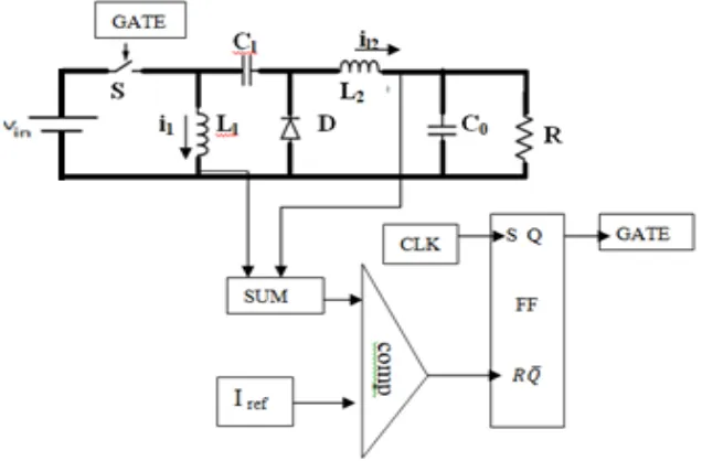
The bifurcation behavior is analyzed using the current mode control technique. In the ZETA converter the reference current is compared with the average of two inductor current values as shown in Fig 1. The compared value is fed to the reset of the SR flip flop. The flip flop is set by the clock pulse with the designed switching frequency. When the actual current is greater than the reference current, the flip flop output goes low, thus the switch is turned off and vice versa.
Figure 1. Average current mode control in ZETA converter
3 of 11
Figure 2. Current Mode Control in CIO Power Buck Boost Converter
TABLE 1: DESIGN PARAMETERS
S.NO
Specifications Range for ZETA converter
Range for CIO Power Buck Boost Converter
1 DC input voltage, Vin 12V 20V
2 Duty ratio, d 75% 75%
3 Output Voltage, Vo 36V -60V
4 Switching frequency,
fs 40kHz
50kHz
5 Inductance, L1, L2 22 mH 1mH
6
Capacitors C1 and C2 680nF C
1=10microF, C2=0.6microF
2.1 Case 1: Simulation Results of ZETA converter 2.1.1 Fundamental Operation
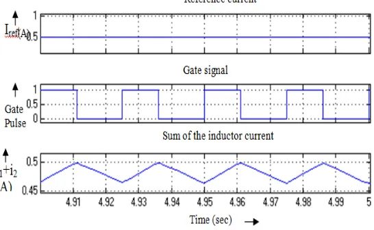
The most common and perhaps the only acceptable operating regime employed in practical power supplies is the fundamental periodic regime. Fig .3 shows the inductor current and capacitor voltage waveforms with the corresponding gate pulses for the fundamental operation for the three bifurcation parameters.
Figure 2. Sum of inductor currents maintained at the set reference
Figure.3. Fundamental operation waveforms with Iref = 0.58A
2.1.2 Period 2 operation
One of the routes to chaos is by period doubling i.e., the period of the limit cycles doubles as the parameter is varied. The doubling occur in smaller and smaller intervals until, in a finite interval, infinitely many period doubling occurs like period 2, period 4, 8, 16,….infinitely. When reference current reaches 0.598A, the inductor current and capacitor voltage waveform for period doubling is shown in Fig.4.
Figure.4. Period doubling with Iref = 0.598A
2.1.3 Chaotic operation
5 of 11
Figure.5. Chaotic waveform with Iref = 0.65A
2.2 Case 2: Simulation Results of CIO Power Buck Boost Converter
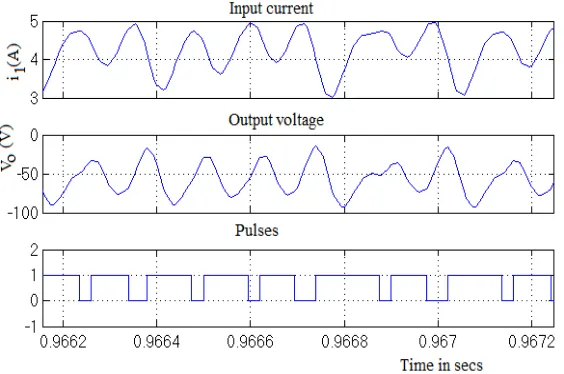
The non-linear characteristics of the converter is analyzed by varying the reference current 𝒊𝒓𝒆𝒇
and the behavior of the circuit is observed. The reference current is set and compared with the inductor current. The switch is turned off when both the currents become equal and turned on according to the clock. The simulated waveform for designed voltage level is shown in Figure.6.The variation in Iref shows different operating regions of the converter. When the reference current
reaches 2.2 A, the fundamental periodic operation is found. The output waveform for stable operation is shown in Figure.7. When the reference current is further increased, the converter loses its stability and it is entering into chaotic region through period doubling bifurcation as shown in Figure.8 and Figure.9.
Figure 6. Simulated waveforms Output Voltage and Input current
Figure 7. Simulated period 1waveform with Iref= 2.2𝐴
Figure 8.Simulated Period 2waveform with Iref= 3.5𝐴
7 of 11 3.Monodromy matrix analysis
The monodromy matrix is derived for both ZETA and CIO Buck Boost converter to find the stability region of the converters.
3.1 Monodromy Matrix Approach for ZETA converter
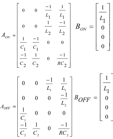
The mode 1 and mode 2 equations are derived from the operation of the ZETA converter as given in equation (1) and (2).
During ON condition of the switch
− − = 2 1 0 2 1 0 0 1 1 2 1 2 1 0 0 0 00
0
0
0
RC C C L L ONA
B
ON=
0 0 2 1 1 1 L L (1)During OFF condition of the switch
− = 0 1 0 0 0 0 0 1 1 0 0 0 0 1 0 0 2 1 2 1 RC C L L AOFF
BOFF =
0 00
0
(2)The following functional equations derived from the above equations.
= − + − 2 4 2 2 1 2 2 2 4 2 3 1 RC x C x C x L in V L x L x L in V ON f = − 2 3 1 1 2 4 1 3 RC x C x L x L x OFF f (3)
Where the state variables are x1=iL1, x2=iL2, x3=Vc1 and x4 =Vc2.
The switching condition is given by
h
(
x
,
t
)
=
I
ref−
(
i
L1(
t
)
+
i
L2(
t
))
=
0
(4)The equiavalent duty ratio is derived from the mode equation and switching condition is given
by
T
L
L
V
V
V
L
i
i
i
d
in C C L L ref n
+
+
−
+
−
=
)
1
1
(
)
(
1
)
(
2 1 2 1 2 2 1 (5)The normal vector based on the above equation is given by
= = 0 0 1 1 4 / 3 / 2 / 1 / x h x h x h x h n (6)The partial differential equation of the switching function from equation (4) is given as
0
=
t
h
(7) The first saltation matrix for the switching event from ON state to OFF state is given as:t h OFF f T n T n OFF f ON f I dT S + − + = / ) ( ) ( 1 (8) = 1 0 0 1 0 0 0 0 42 41 32 31 22 21 12 11 S S S S S S S S (9) 11
S
=
+
−
−
−1
)
)(
(
1 2 4 1 3 1 3 1L
x
L
x
L
x
L
V
in (10) 12S
=
−
−
−12 4 1 3 1 3 1
)
)(
(
L
x
L
x
L
x
L
V
in (11) 21S
=
−
+
−12 4 1 3 2 2
3
)(
)
(
L
x
L
x
L
V
L
x
in (12) 22S
=1+
−
+
−12 4 1 3 2 2 3
)
)(
(
L
x
L
x
L
V
L
x
in (13) 31S
=S
32=
−
−
−12 4 1 3 1 1 1
2
)(
)
(
L
x
L
x
C
x
C
x
(14)The Monodromy matrix is derived using Saltation matrix and state transition matrix is given by:
)
(
2
T
S
M
=
× ()
×
1(
)(
) 1 (
dT
S
e
AoOFF −dTe
AONdT) (15)9 of 11 TABLE 2: EIGEN VALUES OF ZETA CONVERTER
3.2.Monodromy matrix analysis for CIO Power Buck Boost Converter
The monodromy matrix method combines the concept of Floquet theory and Flippov’s method [13]. The state matrices for the ON and OFF periods are given by:
− − − − − = 2 1 0 2 1 2 1 0 0 1 1 1 1 2 1 2 1 0 0 1 1 1 1 0 0 RC C C C C L L L L ON A
=
ONB
0 0 0 1 1 L (16) − − − − = 2 2 2 1 2 1 1 1 0 1 1 0 0 0 1 1 0 0 0 1 1 0 0 RC C C C L L L AOFF = OFF B
0 0 0 1 1 L (17)The linear vector fields before and after switching are:
= − + − + − − + + − 2 4 2 2 2 1 1 2 1 1 2 4 2 3 1 1 4 1 3 RC x C x C x C x C x L x L x L in V L x L x ON f (18) = − + − − + + − 2 4 2 2 2 1 1 1 2 4 1 1 4 1 3 RC x C x C x C x L x L in V L x L x OFF f (19)
Where the state variables are x1=iL1, x2=iL2, x3=Vc1 and x4 =Vc2. The switching condition of the current mode control is given as:
h
(
x
,
t
)
=
I
ref−
i
L(
t
)
=
0
(20) Iref Eigen ValuesAbsolute Value of Complex pair
REMARKS
0.58 0.9967±0.0592 1 0.9924 0.9984 STABLE
0.584 0.9971±0.0588 1 0.9929 0.9988 STABLE
0.586 0.9974±0.0574 1 0.9935 0.999 STABLE
0.588 0.9978±0.0562 1 0.9942 0.9993 STABLE
0.598 0.9989±0.0546 1 0.9954 1.0004 UNSTABLE
0.608 0.9993±0.0522 1 0.9958 1.0006 UNSTABLE
0.625 0.9995±0.0512 1 0.9962 1.0008 UNSTABLE
0.64 0.9997±0.0508 1 0.9968 1.0009 UNSTABLE
0.65 0.9998±0.0506 1 0.9974 1.0011 UNSTABLE
The normal vector for CIO Buck boost converter is given by:
= = 0 0 0 1 4 / 3 / 2 / 1 / x h x h x h x h n (21) Based on the equation(8), the saltation matrix is derived for CIO Buck boost converter as follows) ( 1 dT
S =
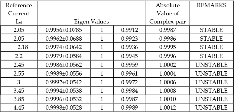
− + + − + − − + + − 1 0 0 0 0 1 0 1 ) 1 1 4 1 3 )( 1 2 1 1 2 ( 0 0 1 1 ) 1 1 4 1 3 ( 2 3 0 0 0 1 L in V L x L x C x C x L in V L x L x L x (22) The Eigen values can be calculated using the Monodromy matrix equation (15) and it is clearly shows that one of the Eigen value crosses the unit circle, when the reference current is reaches above 2.2A as given in Table.3
TABLE 3: EIGEN VALUES FOR CIO BUCK BOOST CONVERTER
4.Conclusion
The stability region of positive output ZETA converter and negative output CIO Power Buck Boost converter were found by simulation results and theoretically by Monodromy matrix approach. It shows that the both the converters loose its stability and enters into chaotic region through period doubling bifurcation. That can be verified by the unit crossover of Eigen values from stable into unstable region. These stability analyses are used to choose the design parameters of the converters within the stable operating region, which can be used in various renewable energy applications.
References
1. C.K.Tse. Complex Behaviour of Switching Power Converters. Boca Raton, FL,CRC Press, 2003.
2. Yesodha, V.; Kavipriya, R.; Jooshna, T.S.; Rajini, V. Analysis of chaos and bifurcation in dc-dc converter using Matlab. In Proceedings of the International Conference on Circuits, Power and Computing, Nagercoil, India, 21–22 March 2013; pp. 481–487.
Reference Current
Iref Eigen Values
Absolute Value of Complex pair
REMARKS
2.05 0.9956±0.0785 1 0.9912 0.9987 STABLE
2.05 0.9962±0.0688 1 0.9923 0.9986 STABLE
2.18 0.9974±0.0642 1 0.9936 0.9995 STABLE
2.2 0.9979±0.0584 1 0.9945 0.9996 STABLE
2.45 0.9986±0.0562 1 0.9959 1.0002 UNSTABLE
2.55 0.9989±0.0556 1 0.9961 1.0004 UNSTABLE
3 0.9992±0.0542 1 0.9972 1.0006 UNSTABLE
3.45 0.9994±0.0538 1 0.9984 1.0008 UNSTABLE
3.85 0.9996±0.0532 1 0.9987 1.0010 UNSTABLE
11 of 11
3. D, Maksimovic,.;Y. Jang.; R. Erickson. Nonlinear-carrier control for high power factor boost rectifiers. IEEE APEC 1995, pp. 635–641.
4. Sukanya,Parui.; S.Banarjee. Bifurcation Due to Transition from Continuous Conduction mode to Discontinuous Conduction Mode in Boost Converter. IEEE Power Electronic Society, 2003; Vol.50,pp.1464-1469.
5. Cheng, K.W.E.;Liu M.;Wu J. Chaos study and parameter-space analysis of the DC-DC buck boost converter. Electric Power Applications, IEE Proceedings 2003;Vol.150,pp.126-138.
6. Kavitha, A.; G. Uma..Resonant Parametric Perturbation Method to Control Chaos in Current Mode Controlled DC-DC Buck-Boost Converter. Journal of Electrical Engineering & Technology, 2010; Vol.5, pp.171-178.
7. Kavitha, A.;G,Uma.; M, BeniReesha.Analysis of fast-scale instability in a power factor correction Cuk converter.IET Power Electronics, 2012;Vol.5,pp.1333-1340.
8. Y.,Chen.; C.K, Tse.; S.C, Wong.; S-S, Qiu. Interaction of fast-scale and slow-scale bifurcations in current-mode controlled dc/dc converters. International Journal of Bifurcation and Chaos 2007; Vol.17: pp.1609-1622. 9. Herbert, H.C.; Zhou, Y.;Tse, C.K.Fast scale instability in a PFC boost converter under average current mode
control. Int. Journal of Circuit Theory and Appl, 2003; Vol.31, pp.611–624.
10. M. G, Ortiz-Lopez.;J, Leyva-Ramos.; L. H,Diaz-Saldierna.; J. M. Garcia-Ibarra.;E. E. Carbajal-Gutierrez. Current-Mode Control for a Quadratic Boost Converter with a Single Switch. IEEE Power Electronics Specialists Conference, 2007; doi: 10.1109/PESC.2007.4342436.
11. Williams,B.W. DC-to-DC Converters with Continuous Input and Output Power. IEEE Power Electronics Society,2013;Vol.28,pp.2307-2316.
12. Abdulmajed, Elbkosh.; Damian, Giaouris.; Volker, Pickert.; Bashar Zahawi.; Soumitro Banerjee. Stability analysis and control of bifurcations of parallel connected DC/DC converters using the monodromy matrix. IEEE International Symposium on Circuits and Systems 2008; doi:10.1109/ISCAS.2008.4541478.
13. I,Daho*.; D, Giaouris.; B, Zahawi.; V, Picker.;S, Banerjee. Stability Analysis and Bifurcation Control of Hysteresis Current Controlled Ćuk Converter Using Filippov’s Method.IET Conference on Power Electronics, Machines and Drives,2008.Print ISBN: 978-0-86341-900-3.
14. Jakkrit, Pakdeeto.; Rangsan,Chanpittayagit.;Kongpan, Areerak.; Kongpol Areerak.The Optimal Controller Design of Buck-Boost Converter by using Adaptive Tabu Search Algorithm Based on State-Space Averaging Model. Journal of Electrical Engineering and Technology 2017;Vol.12,pp.1146-1155.
15. Hao, Zhang.;Yaun,Zhang.;Xikui,Ma. Distortion Behavior Analysis of General Pulse-Width Modulated Zeta PFC Converter Operating in Continuous Conduction Mode. IEEE Transactions On Power Electronics,2012; Vol.27.pp-4212-4223. https://doi.org/10.1109/TPEL.2012.2191161. 16. D.C, Martins.;G.N,De,Abreu.Application of the Zeta converter in switch-mode power
supplies.Proceedings Eighth Annual Applied Power Electronics Conference and Exposition 1993.https://doi.org/10.1109/APEC.1993.290628.