Design and Simulation of Gamma Spectrometry
Experiments in the CROCUS Reactor
O. Pakari
⇤, V. Lamirand
⇤†, B. Vandereydt
⇤, F. Vitullo
⇤, M. Hursin
⇤†, C. Kong
‡, and A. Pautz
⇤† ⇤Laboratory for Reactor Physics and Systems BehaviourEcole polytechnique f´ed´erale de Lausanne, Lausanne, Switzerland [email protected]
†Laboratory for Reactor Physics and Thermal-Hydraulics
Nuclear Energy and Safety Division Paul Scherrer Institut, Villingen, Switzerland
‡Ulsan National Institute of Science and Technology
Ulsan, South Korea
Abstract—Gamma rays in nuclear reactors, arising either from fission or decay processes, significantly contribute to the heating and dose of the reactor components. Zero power research reactors offer the possibility to measure gamma rays in a purely neutronic environment, allowing for validation experiments of computed spectra, dose estimates, reactor noise and prompt to delayed gamma ratios. This data then contributes to models, code validation and photo atomic nuclear data evaluation. In order to contribute to aforementioned experimental data, gamma detection capabilities are being added to the CROCUS reactor facility. The CROCUS reactor is a two-zone, uranium-fueled light water moderated facility operated by the Laboratory for Reactor Physics and Systems Behaviour (LRS) at the Swiss Federal Institute of Technology Lausanne (EPFL). With a maximum power of 100 W, it is a zero power reactor used for teaching and research, most recently for intrinsic and induced neutron noise studies. For future gamma detection applications in the CROCUS reactor, an array of four detectors - two large 5”x10” Bismuth Germanate (BGO) and two smaller Cerium Bromide (CeBr3) scintillators - was acquired. The BGO detectors are to
be arbitrarily positioned in the core reflector and out of the vessel for measurements at arbitrary distances. The CeBr3detectors on
the other hand are small enough to be set in the guide tubes of the control rods for in-core measurements. We present a study of the neutron and gamma flux in the core and reflector using the MCNP 6.2 and Serpent 2 Monte Carlo codes for coupled neutron and photon transport criticality calculations. More specifically, we investigate and compare predicted spectra as well as reactivity worth of different envisioned experimental setups. We further predict pulse height spectra as well as doses to the crystals with and without cadmium shielding to estimate allowable reactor powers with respect to detector radiation hardness. The results serve as basis for calibration and aid in the design and regulatory approval of the experiments.
I. INTRODUCTION
Gamma radiation as a by-product of fission and radioactive decay is a major component of a nuclear reactors radiation field. It contributes to the heating of structures, the degradation of materials, and the overall dose rate around a reactor. The characteristics of a reactors gamma field is thus important for operation and safety. Accurate predictions are desired in the design of experiments and in the inception of new reactors.
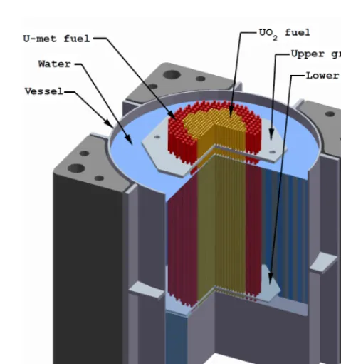
Fig. 1. The CROCUS reactor vessel with basic internal structures. Two fuel zones, an inner UO2 and outer Umet zone, held in an approximately cylindrical array by two grids. Water is filled from the bottom to establish criticality.
Quantitative experiments on the spectra and fluxes of gamma radiation have become of recent interest with the introduction of coupled photon and neutron transport options in common Monte Carlo codes, such as Serpent and MCNP. On top of a relatively well characterized neutron field, the predicted photon fluxes and spectra lack experimental data for validation. The CROCUS reactor, presented in Section II, offers a zero power environment to provide such data.
analysis. With a variety of experimental programs (e.g. [1], [2]) that so far only exploited neutron detection, the acquisition of gamma detectors intends to extend the capabilities of CROCUS.
II. THERESEARCHREACTORCROCUS
The description of CROCUS follows [2]. The CROCUS reactor is a two-zone, uranium-fueled, H2O-moderated critical
assembly operated by the Laboratory for Reactor Physics and Systems Behaviour (LRS) at the Swiss Federal Institute of Technology Lausanne (EPFL). It is a zero power reactor, with a maximum power of up to 100 W. The core is approximately cylindrical in shape with a diameter of about 58 cm and a height of 100 cm. Two different kinds of fuel rods make up the reactor core of CROCUS (see Fig. 1 and 3). The central zone is loaded with 336 UO2fuel rods (1.806 wt.%-enriched),
set in a square lattice with a pitch of 1.837 cm. The peripheral zone is loaded with up to 176 thicker, Umet fuel rods (0.947 wt.%-enriched) with a pitch of 2.917 cm, also in a square lattice. All fuel rods have an aluminum cladding and are maintained in a vertical position by the upper grid and lower grid plates spaced 100 cm apart. Both grid plates incorporate a cadmium layer with a thickness of 1 mm to limit axial thermal leakage to surrounding structures. The active fuel length starts at the top surface of the lower cadmium layer and extends to 100 cm. The core is located in an aluminum water tank, its diameter is 130 cm and thickness is 1.2 cm. Demineralized light water is used as moderator and reflector. Reactivity is nominally controlled by a variation of the water level using a spillway with an accuracy of 0.1 mm (equivalent to 0.4 pcm) and optionally by means of two control rods containing naturally enriched boron carbide (B4C) sintered pellets located
in diagonal symmetry within the outer fuel zone.
III. NEW GAMMA DETECTION EXPERIMENT FORCROCUS A. Detector specification
The new gamma detection array to be used in the CROCUS core was chosen to be on scintillator basis. The most prominent measurement locations in CROCUS are, due to their accessibility, the two control rod tubes and the water reflector.
In the control rod position we expect a higher overall photon flux and due to the proximity to the fuel. Thus, a fast scintillator usable for spectroscopy - Cerium(III) Bromide (CeBr3) - was chosen. The control rod tubes constrain the
cylindrical crystal size to 13 mm in diameter and 15 mm in length. Two detectors to measure simultaneously in both control rod tubes were acquired from Scionix Holland [3]. Both house a Hamamatsu Type R12421 PMT.
For the periphery location, which is less constrained due to the large vessel radius holding the water reflector, a high Z scintillator for maximal efficiency - Bismuth Germanate (BGO) - was chosen. The size of the cylindrical crystal is 127 mm in diameter to increase the absorption efficiency to
576
mm
166 mm
CeBr
3BGO
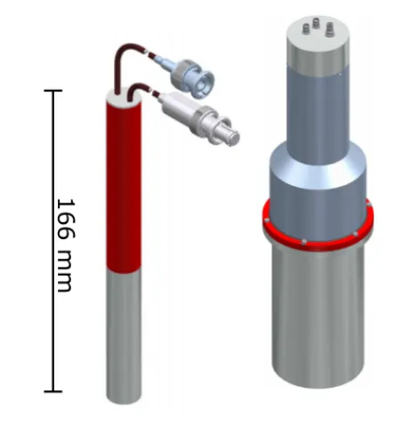
Fig. 2. CAD drawing of the detectors to be used in CROCUS.Left:CeBr3 detector with 0.6”x2” cylindrical crystal (silver) and PMT with I/O cables (red).Right:BGO detector with 5”x5” cylindrical crystal (silver) and PMT with connectors (grey).
above 95% of 10 MeV photons. The height was constrained by weight and is 250 mm. Two detectors of this type were acquired. Both house a Photonis 5” Type XP4578 PMT. The detectors CAD models are shown in Figure 2.
B. Envisioned detector locations in CROCUS
The CeBr3detectors can be moved axially in the control rod
guide tubes, but also set in the reflector if deemed relevant. The BGOs are envisioned to be set in arbitrary locations in the reflector to measure effects at a distance. For the purpose of modeling the reactivity impact of the detector array and dose estimates, a reference setup at mid-core height and close to the fuel was used (see Figure 3).
IV. MONTECARLO SIMULATION OF THE EXPERIMENT
To model the future experiments using the acquired detectors, we used the to-date newest releases of two commonly used Monte Carlo transport codes: Serpent 2 (Version 2.1.30) [4] and MCNP 6.2 [5]. MCNP, with its long development history, is often used as reference for criticality and shielding calculations. Since around 2000 [6], coupled neutron photon transport is a standard feature of MCNP. Serpent features photon transport since Version 2.1.24 [7]. Both codes are frequently used at LRS for neutron transport in CROCUS - we hence chose to compare the codes for future reference.
The examined setups are listed in Table I. As the control rod tubes are already in place, no further measures need to be taken for the CeBr3 usage. The BGO detectors are not
analysis. With a variety of experimental programs (e.g. [1], [2]) that so far only exploited neutron detection, the acquisition of gamma detectors intends to extend the capabilities of CROCUS.
II. THERESEARCHREACTORCROCUS
The description of CROCUS follows [2]. The CROCUS reactor is a two-zone, uranium-fueled, H2O-moderated critical
assembly operated by the Laboratory for Reactor Physics and Systems Behaviour (LRS) at the Swiss Federal Institute of Technology Lausanne (EPFL). It is a zero power reactor, with a maximum power of up to 100 W. The core is approximately cylindrical in shape with a diameter of about 58 cm and a height of 100 cm. Two different kinds of fuel rods make up the reactor core of CROCUS (see Fig. 1 and 3). The central zone is loaded with 336 UO2fuel rods (1.806 wt.%-enriched),
set in a square lattice with a pitch of 1.837 cm. The peripheral zone is loaded with up to 176 thicker, Umetfuel rods (0.947 wt.%-enriched) with a pitch of 2.917 cm, also in a square lattice. All fuel rods have an aluminum cladding and are maintained in a vertical position by the upper grid and lower grid plates spaced 100 cm apart. Both grid plates incorporate a cadmium layer with a thickness of 1 mm to limit axial thermal leakage to surrounding structures. The active fuel length starts at the top surface of the lower cadmium layer and extends to 100 cm. The core is located in an aluminum water tank, its diameter is 130 cm and thickness is 1.2 cm. Demineralized light water is used as moderator and reflector. Reactivity is nominally controlled by a variation of the water level using a spillway with an accuracy of 0.1 mm (equivalent to 0.4 pcm) and optionally by means of two control rods containing naturally enriched boron carbide (B4C) sintered pellets located
in diagonal symmetry within the outer fuel zone.
III. NEW GAMMA DETECTION EXPERIMENT FORCROCUS A. Detector specification
The new gamma detection array to be used in the CROCUS core was chosen to be on scintillator basis. The most prominent measurement locations in CROCUS are, due to their accessibility, the two control rod tubes and the water reflector.
In the control rod position we expect a higher overall photon flux and due to the proximity to the fuel. Thus, a fast scintillator usable for spectroscopy - Cerium(III) Bromide (CeBr3) - was chosen. The control rod tubes constrain the
cylindrical crystal size to 13 mm in diameter and 15 mm in length. Two detectors to measure simultaneously in both control rod tubes were acquired from Scionix Holland [3]. Both house a Hamamatsu Type R12421 PMT.
For the periphery location, which is less constrained due to the large vessel radius holding the water reflector, a high Z scintillator for maximal efficiency - Bismuth Germanate (BGO) - was chosen. The size of the cylindrical crystal is 127 mm in diameter to increase the absorption efficiency to
576
mm
166 mm
CeBr
3BGO
Fig. 2. CAD drawing of the detectors to be used in CROCUS.Left:CeBr3 detector with 0.6”x2” cylindrical crystal (silver) and PMT with I/O cables (red).Right:BGO detector with 5”x5” cylindrical crystal (silver) and PMT with connectors (grey).
above 95% of 10 MeV photons. The height was constrained by weight and is 250 mm. Two detectors of this type were acquired. Both house a Photonis 5” Type XP4578 PMT. The detectors CAD models are shown in Figure 2.
B. Envisioned detector locations in CROCUS
The CeBr3detectors can be moved axially in the control rod
guide tubes, but also set in the reflector if deemed relevant. The BGOs are envisioned to be set in arbitrary locations in the reflector to measure effects at a distance. For the purpose of modeling the reactivity impact of the detector array and dose estimates, a reference setup at mid-core height and close to the fuel was used (see Figure 3).
IV. MONTECARLO SIMULATION OF THE EXPERIMENT
To model the future experiments using the acquired detectors, we used the to-date newest releases of two commonly used Monte Carlo transport codes: Serpent 2 (Version 2.1.30) [4] and MCNP 6.2 [5]. MCNP, with its long development history, is often used as reference for criticality and shielding calculations. Since around 2000 [6], coupled neutron photon transport is a standard feature of MCNP. Serpent features photon transport since Version 2.1.24 [7]. Both codes are frequently used at LRS for neutron transport in CROCUS - we hence chose to compare the codes for future reference.
The examined setups are listed in Table I. As the control rod tubes are already in place, no further measures need to be taken for the CeBr3 usage. The BGO detectors are not
watertight and require a housing. For the simulations we
Fig. 3. Top:XY-view of the CROCUS Serpent 2 model at mid core height. The CeBr3 are set in the control rod positions (2), while the BGOs are set into the reflector close to the fuel.Middle:ZX-view of the CROCUS core control rod tube with inserted CeBr3. Bottom:ZX-view of the CROCUS core, showing a BGO detector.
will assume a Plexiglas cylinder to fill said role. The actual realization will depend on mechanical tests, as the crystal weighs more than 20 kg and thus might require custom made aluminium or steel solutions. In addition to the full array of four detectors, we examined single detector setups as
TABLE I
DETECTOR SETUP ABBREVIATIONS.
Detector set-up Name
Reference (no detectors) Ref
No Cd, 1 BGO N1B
No Cd, 1 CeBr3 N1C
No Cd, 1 BGO, 1 CeBr3 N1B1C No Cd, 2 BGO, 2 CeBr3 N2B2C
With Cd, 1 BGO Y1B
With Cd, 1 CeBr3 Y1C
With Cd, 1 BGO, 1 CeBr3 Y1B1C With Cd, 2 BGO, 2 CeBr3 Y2B2C
TABLE II
SERPENT VS. MCNP: RELATIVE REACTIVITY IMPACT FOR THE DIFFERENT
SETUPS WITH RELATIVE DIFFERENCE BETWEEN THE TWO CODES.
∆⇢Serpent ∆⇢M CN P ∆ ⇢
Ref 0 0
N1B -27±3 -22±4 19 %
N1C -3±3 -11±4 -267 %
N1B1C -35±3 -23±4 34 %
N2B2C -47±3 -39±4 17 %
Y1B -67±3 -45±4 33 %
Y1C -73±3 -60±4 18 %
Y1B1C -143±3 -108±4 24 % Y2B2C -245±3 -178±4 27 %
well as setups with the detector crystals shielded by 1 mm cadmium. We present the comparison of reactivity worth, integral neutron/photon fluxes, and spectra. Pulse height or dose deposition tallies are not available in Serpent, and MCNP results will be presented without comparison. For all calculations we used a water level of 955 mm and the nuclear data library ENDF/B-7.1.
A. Reactivity of different setups
One of the initial quantities of interest for the gamma experiment is the relative reactivity impact of their introduction into the core. CROCUS is constrained within regulatory boundaries to an excess of 200 pcm. Any proposed experiment requires thus, on top of calculations showing the reactivity impact, further considerations regarding mechanical stability and water incursion scenarios. As shown in Table II, a significant re-structuring and associated re-approval of CROCUS will not be necessary. Only in the case of fully Cd-shielded detectors does Serpent predict a reactivity
< −200pcm. As discussed in Section IV.3, the dose to the detectors was found to be small enough to not require shielding. As such, the proposed setups are within regulatory limits and ready to be installed once the detectors are available.
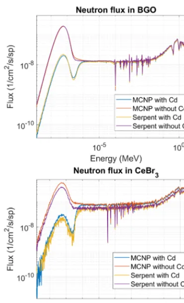
Fig. 4. Neutron fluxes predicted by MCNP and Serpent.Top:Flux tallied in the BGO detector with and without Cd shielding.Bottom:Flux tallied in the CeBr3 detector with and without Cd shielding.
around 30%, and by -267% in an extreme case. A deviation of the absolute values ofkef f was expected and indeed found to be consistently 150 pcm. This is nonetheless an atypical high difference. The relative worths, however, should agree within statistical uncertainties. This points to a deficiency in the models and requires a re-evaluation. This will also be reflected in the thermal neutron spectrum predicted, as shown in the next Section.
B. Neutron and photon flux
Part of the analysis was the calculation and comparison of neutron and photon flux spectra. Due to the symmetry of the setup we focused on one CeBr3 and BGO. The
results for neutron spectra with and without Cd shield, using Serpent and MCNP, are displayed in Figure 4. Overall, we find a good agreement between the codes, with differences arising in the thermal region for the CeBr3. These
differences could not be explained by statistical means and once more point to minor differences in the respective models.
The resulting photon spectra of both detectors are displayed and compared in Figure 5. Here we find similarly agreeing spectra between Serpent and MCNP. Note that any Cd(n, ) peaks are not visible as the production cross-sections are missing in ENDF/B-7.1.
BiL I & II
H(n,)
H(n,) 511 keV BiK
511 keV
CeK
Fig. 5. Photon fluxes predicted by MCNP and Serpent.Top:Flux tallied in the BGO detector with and without Cd shielding.Bottom:Flux tallied in the CeBr3detector with and without Cd shielding.
TABLE III
INTEGRAL NEUTRON AND PHOTON FLUXES IN FLUX PER SOURCE
PARTICLE,ΦnANDΦγ,WITH RELATIVE STATISTICAL UNCERTAINTIES
AND RELATIVE DIFFERENCE BETWEEN THE CODES.
Serpent MCNP ∆
Φn(BGO) 3.103·10 5±1% 3.108·10 5±0.05% 0.1%
Φn(CeBr3) 1.398·10 4±1% 1.449·10 4±0.05% 3.6%
Φγ(BGO) 1.029·10 5±1% 1.005·10 5±0.05% 2.3%
Φγ(CeBr3) 7.652·10 5±1% 7.644·10 5±0.05% 0.1%
The integral neutron and photon fluxes in comparison are shown in Table III. Overall we can state that the photon flux to neutron flux ratio is higher in-core than ex-core, and that Serpent and MCNP only differ by up to 3%. This largest difference is again for the CeBr3, probably indicating a
modeling error.
C. Pulse height spectrum
Fig. 4. Neutron fluxes predicted by MCNP and Serpent.Top:Flux tallied in the BGO detector with and without Cd shielding.Bottom:Flux tallied in the CeBr3 detector with and without Cd shielding.
around 30%, and by -267% in an extreme case. A deviation of the absolute values ofkef f was expected and indeed found to be consistently 150 pcm. This is nonetheless an atypical high difference. The relative worths, however, should agree within statistical uncertainties. This points to a deficiency in the models and requires a re-evaluation. This will also be reflected in the thermal neutron spectrum predicted, as shown in the next Section.
B. Neutron and photon flux
Part of the analysis was the calculation and comparison of neutron and photon flux spectra. Due to the symmetry of the setup we focused on one CeBr3 and BGO. The
results for neutron spectra with and without Cd shield, using Serpent and MCNP, are displayed in Figure 4. Overall, we find a good agreement between the codes, with differences arising in the thermal region for the CeBr3. These
differences could not be explained by statistical means and once more point to minor differences in the respective models.
The resulting photon spectra of both detectors are displayed and compared in Figure 5. Here we find similarly agreeing spectra between Serpent and MCNP. Note that any Cd(n, ) peaks are not visible as the production cross-sections are missing in ENDF/B-7.1.
BiL I & II
H(n,)
H(n,) 511 keV
BiK
511 keV
CeK
Fig. 5. Photon fluxes predicted by MCNP and Serpent.Top:Flux tallied in the BGO detector with and without Cd shielding.Bottom:Flux tallied in the CeBr3detector with and without Cd shielding.
TABLE III
INTEGRAL NEUTRON AND PHOTON FLUXES IN FLUX PER SOURCE
PARTICLE,ΦnANDΦγ,WITH RELATIVE STATISTICAL UNCERTAINTIES
AND RELATIVE DIFFERENCE BETWEEN THE CODES.
Serpent MCNP ∆
Φn(BGO) 3.103·10 5±1% 3.108·10 5±0.05% 0.1%
Φn(CeBr3) 1.398·10 4±1% 1.449·10 4±0.05% 3.6%
Φγ(BGO) 1.029·10 5±1% 1.005·10 5±0.05% 2.3%
Φγ(CeBr3) 7.652·10 5±1% 7.644·10 5±0.05% 0.1%
The integral neutron and photon fluxes in comparison are shown in Table III. Overall we can state that the photon flux to neutron flux ratio is higher in-core than ex-core, and that Serpent and MCNP only differ by up to 3%. This largest difference is again for the CeBr3, probably indicating a
modeling error.
C. Pulse height spectrum
The predicted spectra in the detectors are naturally not an observable, and serve mostly as baseline for what can be expected to be seen in an optimal case. The true response of a detector will depend on the energy deposition of the individual photons that enter the detector. Pulse height tallies allow to capture this behavior. In MCNP this includes the explicit
H(n,)
H(n,) - 511 keV H(n,)
2xH(n,)
511 keV
H(n,) - 2x 511 keV
Fig. 6. Pulse height spectra estimated using the F8 tally of MCNP. Prominent peaks, such as annihilation, absorption in water and (double) escape, are highlighted.
modeling of secondary particles (electrons and photons) and their energy deposit. For both detector types we produced said tallies and display them in Figure 6. Note that the pulse height spectra are an approximation of the energy deposited in the crystal volume and do not take individual scintillation properties into account. We observe that from the initial photon spectrum we expect to observe mostly a lumped spectrum. The peaks due to the H(n, ) and annihilation reactions are nonetheless visible. Single and double escapes as well as sum deposits of H(n, ) are also visible. This spectrum provides a first prediction that will be compared to experiments.
D. Deposited dose
The crystals are damaged by the radiative environment and over time lose light yield. For this purpose, we investigated the dose in dependence of energy for neutrons and photons respectively as well as integral doses, with and without cadmium shielding.
The dose rate was estimated using the dose deposition tally in MCNP. More specifically, we used an ICRP-60 dose function that uses stopping power dependent tables to convert the deposited energy. We display the neutron dose over energy results in Figure 7, whilst Figure 8 displays the results for photons. We can state that the photon dose approximately follows the spectral shape, as is expected due to quality factors being defined at unity for photons. A general decrease in flux due to attenuation, as expected, can be seen. The neutron doses reveal that ex-core BGO measurements do not benefit from a Cd shield, as most of the dose is received from fast neutrons. In-core measurements using the CeBr3 would see a larger
positive impact of a shielding. In Table IV we summarize the individual integral dose components.
The integral results were weighted with the core average source per watt, as determined in [8], to receive values per Watt, as presented in Table IV.
Fig. 7. Neutron dose over neutron energy in the detectors of the gamma detection array, with and without cadmium shield.
TABLE IV
INTEGRAL NEUTRON,PHOTON,AND TOTAL DOSES INSIEVERT PER HOUR
PERWATT,Dn,Dγ,ANDDtot,WITH AND WITHOUT CADMIUM
SHIELDING. RESULTS ARE DISPLAYED WITH RELATIVE STATISTICAL
UNCERTAINTIES.
MCNP (Sv/h/W) Dn(BGO) 0.011±0.1%
Dn(BGO+Cd) 0.010±0.1%
Dγ(BGO) 0.024±0.1%
Dγ(BGO+Cd) 0.014±0.1%
Dn(CeBr3) 3.310±0.1%
Dn(CeBr3+Cd) 1.136±0.1%
Dγ(CeBr3) 0.114±0.1%
Dγ(CeBr3+Cd) 0.102±0.1%
Dtot(BGO) 0.035
Dtot(BGO+Cd) 0.024
Dtot(CeBr3) 3.424
Dtot(CeBr3+Cd) 1.238
The Cd shield resulted in a total dose reduction by 30% in the BGO, and by 64% in the CeBr3. Literature revealed
that BGO shows a 15% yield decrease at 102 kGy [9], whilst CeBr3 suffer a 7% decrease in yield at 111 kGy [10]. The
unshielded BGO could thus withstand 2.91 MWh until it reaches 15% yield decrease, while the CeBr3 32 kWh until
Fig. 8. Photon dose over photon energy in the detectors of the gamma detection array, with and without cadmium shield.
power of CROCUS, and that the detectors are to be used in
<1 W or sub-critical configurations, that a Cd shield will not
be necessary. The reactivity concerns mentioned before are hence also alleviated. The Cd shield could nonetheless be used to force Cd(n, ) reactions and possibly monitor neutrons simultaneously to gammas.
V. CONCLUSION
In this study, we presented the simulation results of a new gamma detection experiment for the CROCUS reactor. A recently acquired array of four scintillation based gamma detectors are to extend the capabilities of the CROCUS facility: Two large BGO, to be set in the spacious water reflector, and two smaller CeBr3 detectors, to be set in the
control rod guide tubes. Various setups were modeled in common Monte Carlo transport codes. We compared the codes MCNP 6.2 and Serpent 2.1.30 with respect to their coupled neutron photon transport capabilities, using the ENDF/B-7.1 library.
Relative reactivities were found to deviate, with Serpent over-predicting MCNP by ⇠30%. The codes showed overall good agreement with regards to photon and neutron flux predictions, with exceptions found in the thermal neutron spectrum in-core. Both deviations point to minor differences
in the models around the control rod tube. The reflector region fluxes showed < 3% relative difference between the codes, affirming that the codes produce consistent results.
Using MCNP only, we also predicted the dose received and pulse height spectrum of the detectors. The dose estimations allowed us to conclude that a Cd shielding will not be necessary, as the radiation hardness of both crystal types should suffice even in extreme conditions of CROCUS operation. The Cd shield was in fact shown to only contribute to a 30% dose reduction in the reflector, as most energy is deposited by fast neutrons. The pulse height spectra will be used as expectation for eventually observable spectra.
This study will be continued by examining the possible errors in either model. Next we will supply calibration and characterization data of the detectors. Finally, first in core measurements will be compared to the presented results.
REFERENCES
[1] Lamirand, V. P., Hursin, M., Perret, G., Frajtag, P., Pakari, O., & Pautz, A. (2016). Future experimental programmes in the CROCUS reactor. In Conference proceedings of RRFM/IGORR 2016 (No. CONF, pp. 284-292).
[2] Pakari, O., Lamirand, V., Perret, G., Frajtag, P., & Pautz, A. (2018). Kinetic Parameter Measurements in the CROCUS Reactor Using Current Mode Instrumentation. IEEE Transactions on Nuclear Science, 65(9), 2456-2460.
[3] Scionix Holland. Mechanical, optical and scintillation properties. https://scionix. nl/scintillation-crystals/#tab-id-4. Accessed: 11/12/18. [4] Lepp¨anen, J., et al. (2015) ”The Serpent Monte Carlo code: Status,
development and applications in 2013.” Ann. Nucl. Energy, 82 (2015) 142-150.
[5] C.J. Werner, et al., ”MCNP6.2 Release Notes”, Los Alamos National Laboratory, report LA-UR-18-20808 (2018).
[6] White, M. C. (2000). Development and implementation of photonuclear cross-section data for mutually coupled neutron-photon transport calcula-tions in the Monte Carlo N-particle (MCNP) Radiation Transport Code. [7] Kaltiaisenaho, T. (2016) ”Implementing a photon physics model in
Serpent 2.” M.Sc. Thesis, Aalto University, 2016.
[8] Pakari, O., Lamirand, V., Perret, G., Braun, L., Frajtag, P., & Pautz, A. (2018). Current mode neutron noise measurements in the zero power reactor CROCUS. In EPJ Web of Conferences (Vol. 170, p. 04017). EDP Sciences.
[9] Sahu, S. K., Peng, K. C., Huang, H. C., Wang, C. H., Chang, Y. H., Hou, W. S., ... & Wei, Y. Y. (1997). Radiation hardness of undoped BGO crystals. Nuclear Instruments and Methods in Physics Research Section A: Accelerators, Spectrometers, Detectors and Associated Equipment, 388(1-2), 144-148.