The Cherenkov Telescope Array production system for
data-processing and Monte Carlo simulation
LuisaArrabito1,∗,KonradBernlöhr2,JohanBregeon1,PaoloCumani3,TarekHassan4,
An-dreasHaupt4,GernotMaier4,AbelardoMoralejo3,NadineNeyroud5for the CTA Consor-tium
FedericoStagni6, andAndreiTsaregorodtsev7for the DIRAC Consortium
1Laboratoire Univers et Particules, Université de Montpellier Place Eugène Bataillon - CC 72, CNRS/IN2P3, F-34095 Montpellier, France
2Max-Planck-Institut für Kernphysik, P.O. Box 103980, D-69029 Heidelberg, Germany
3Institut de Fisica d’Altes Energies (IFAE), The Barcelona Institute of Science and Technology, Campus UAB, 08193 Bellaterra Barcelona, Spain
4Deutsches Elektronen-Synchrotron, Platanenallee 6, 15738 Zeuthen, Germany
5Laboratoire d’Annecy-le-Vieux de Physique des Particules, Université Grenoble Alpes, Université Savoie Mont Blanc, CNRS/IN2P3, F-74000 Annecy, France
6CERN PH Department, CH-1211 Geneva 23 Switzerland
7Centre de Physique des Particules de Marseille, 163 Av de Luminy Case 902, CNRS/IN2P3, 13288 Marseille, France
Abstract. The Cherenkov Telescope Array (CTA) is the next-generation in-strument in the field of very high energy gamma-ray astronomy. It will be com-posed of two arrays of Imaging Atmospheric Cherenkov Telescopes, located at La Palma (Spain) and Paranal (Chile). The construction of CTA has just started with the installation of the first telescope on site at La Palma and the first data expected by the end of 2018. The scientific operations should begin in 2022 for a duration of about 30 years. The overall amount of data produced during these operations is around 27 PB per year. The associated computing power for data processing and Monte Carlo (MC) simulations is of the order of hundreds of millions of CPU HS06 hours per year. In order to cope with these high com-puting requirements, we have developed a production system prototype based on the DIRAC framework, that we have intensively exploited during the past 6 years to handle massive MC simulations on the grid for the CTA design and prototyping phases. CTA workflows are composed of several inter-dependent steps, which we used to handle separately within our production system. In order to fully automatize the whole workflows execution, we have partially re-vised the production system by further enhancing the data-driven behavior and by extending the use of meta-data to link together the different steps of a work-flow. In this contribution we present the application of the production system to the last years MC campaigns as well as the recent production system evolution, intended to obtain a fully data-driven and automatized workflow execution for efficient processing of real telescope data.
1 Introduction
In order to handle massive Monte Carlo productions on the EGI (European Grid Initiative [1]) grid for the CTA Consortium [2], we have developed a production setup based on the DIRAC framework [3][4] (CTA–DIRAC setup). The main DIRAC systems in use in our setup are: 1) the Workload Management System (WMS) for the job submission, scheduling and distribution; 2) the Data Management System (DMS) dealing with all data operations; 3) the Transformation System to automate tasks for large productions. Additionally, we rely on the DIRAC File Catalog as replica and meta-data catalog for the different datasets stored
on the grid. The DIRAC hardware infrastructure is composed of 5 servers distributed among 3 computing centers: CC–IN2P3 (Centre de Calcul de l’IN2P3), PIC (Port d’Informació Científica) and DESY (Deutsches Elektronen-Synchrotron). For the software deployment and access by grid jobs we rely on the CVMFS [5] system with a Stratum-0 server hosted at CC–IN2P3 and two Stratum-1 servers at CC–IN2P3 and DESY. Finally, we have developed a CTA specific software extension to DIRAC, mainly to simplify the job configuration and submission of several CTA applications. More details on the CTA–DIRAC setup can be found in [6]. The only recent infrastructure evolution in this setup concerns the migration of the DIRAC databases hosted at CC–IN2P3 to a MariaDB/Galera cluster [7] with a master
server and two slaves. From the point of view of the accessed computing resources, we have also integrated for the first time some cloud resources in the CTA–DIRAC setup. The details of this integration and the first scalability tests are presented in Section 2. In Section 3 we present the utilization of the CTA–DIRAC setup for the MC productions during the past couple of years. Finally, in Section 4 we present a new high-level system that we have developed to further automatize workflows execution, the so–called Production System.
2 Cloud resources integration
The use of cloud resources in scientific collaborations is starting to be more and more com-mon [8][9]. In order to be prepared to efficiently benefit from cloud resources that may
be available to the CTA Consortium, we have tested their integration in the CTA–DIRAC setup. The target clouds are both academic, i.e. LUPM (Laboratoire Univers et Particules de Montpellier) and CC–IN2P3 cloud sites of the French NGI (National Grid Initiative), and commercial clouds in the context of the HNSciCloud project [10].
For the job management on cloud resources, DIRAC provides a specific extension, called VMDIRAC. First of all, we have installed VMDIRAC on one of the DIRAC servers, then we have inserted the cloud sites description in the DIRAC configuration. Finally, we have performed extensive tests of VMDIRAC functionalities by submitting and executing typical CTA jobs on the configured cloud sites. Even though our target sites were all using the OpenStack [11] cloud solution, VMDIRAC has several plugins to interface different cloud
managers (OpenStack, OCCI [12], OpenNebula [13], etc.) in a transparent way. VMDIRAC is responsible for instantiating, monitoring and discarding virtual machines on the different
supported clouds. Once a virtual machine is instantiated, a DIRAC pilot [14] is run within the contextualization process. Then, the pilot installs DIRAC on the virtual machine and runs a ‘JobAgent’ that matches and pulls payloads from the central DIRAC task queue. Pilots running on virtual machines are standard DIRAC pilots, identical to those running on grid worker nodes. The usage of cloud resources is thus completely transparent for users, who don’t need to apply any specific modification to their job description.
In our tests, cloud jobs are identical to standard CTA grid jobs. They execute CTA appli-cations and interact with grid storage elements to access input data and upload their output. In order to enable cloud jobs to access CTA software in the same way as grid jobs, we have
added to the contextualization process the installation of the CVMFS client. Concerning the CTA software applications, we have tested two different types of jobs: 1) MC simulation; 2)
MC analysis. The first class of jobs is CPU–intensive and well adapted to be executed on clouds. Several experiments already use clouds as extra resources to absorb CPU peaks in large MC simulation campaigns. On the other hand, jobs of the second class require access to input data that are external to the cloud. The efficiency of these jobs is thus affected by the
network connectivity between clouds and the storage systems hosting the data. In our case, MC analysis jobs access CTA official datasets, distributed in 3 storage elements. On average,
each job downloads about 5 GB of input data.
In the first phase of our tests, we have submitted a limited number of jobs to the different
cloud sites. For both categories of jobs, these functional tests have been successful. In par-ticular, we have been able to perform all job management tasks (e.g.submission, monitoring and output retrieval) using the standard DIRAC client interfaces (command line, python API and web portal).
In the second phase, we have performed preliminary scalability tests using all the re-sources available. LUPM and CC–IN2P3 each allocated 50 4-cores virtual machines, while the commercial cloud site allocated 250 4-cores virtual machines. Since each virtual machine can host 1 job per core, we have been able to ramp up to 200 concurrent jobs at LUPM and CC–IN2P3 sites and up to 1000 concurrent jobs on the commercial cloud. During these tests, no scalability issue has arisen when running MC simulations jobs. However, in our first trial with MC analysis jobs, many failures occurred due to a slow access to input data. Some network configuration tuning on the cloud side has been necessary to solve the data access problem. In the end, no further scalability issues have been observed for both categories of jobs.
In conclusion, we have successfully integrated cloud resources in the CTA–DIRAC setup. First functional and scalability tests have shown that these resources can be efficiently used
for CTA simulation and processing, provided there is a good network connectivity between clouds and storage systems.
3 Monte Carlo productions
3.1 Prod3(b) simulation and analysis
The CTA–DIRAC setup has been successfully employed during the last 6 years to handle several MC productions on the grid. Among the most important achievements obtained using CTA–DIRAC, we cite the CTA performance evaluation [15], the MC site selection studies [16] and the baseline telescope layout studies [17]. In this long period of exploitation, we have evaluated many DIRAC functionalities and tested the scalability of the various DIRAC systems. In particular, we have intensively used the DIRAC WMS to access the computing resources available to the CTA Virtual Organization (about 20 grid sites, a standalone cluster and two cloud sites), using 8000-10000 cores at a time and consuming about 100 million CPU HS06 hours each year.
The last large-scale production, named Prod3(b), started in early 2017 and lasted until September 2018. The goal of Prod3(b) was to derive a new set of instrument response func-tions corresponding for the first time to what CTA will really be: the setup includes the two official geographic sites at Paranal (Chile) and La Palma (Canary Islands, Spain), the final
cover-ing 2 azimuth angles (North and South, important with respect to the local magnetic field) and 3 zenith angles.
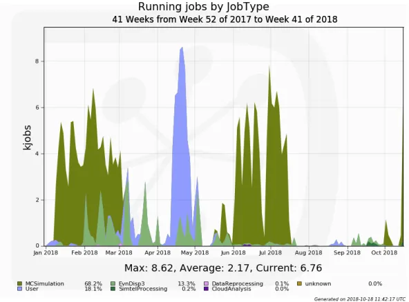
The last phase of the production in 2018 was the 60 degree zenith angle pointing, that was actually the most computationally intensive part. Indeed, at high zenith angle, particles cross a significantly larger slant of the atmosphere resulting in a shift of the efficiency of the detector to higher energies (showers at high energies contain many more particles), hence increasing exponentially the computational requirements of the air shower simulation part. In Figure 1, we report the number of concurrent running jobs since January 2018 classified by type, i.e. centrally managed MC productions (simulation and analysis) and users jobs. Peaks up to 8000 concurrent jobs were observed this year, and in total more than 2.2 million jobs were executed for a cumulative normalized CPU time of 150 million CPU hours.
Figure 1.Concurrent running jobs in 2018. Different colors represent different job types (MC simula-tion, processing with different software and users jobs). The sustained activity from January to May is due to the MC simulation with the full array at Paranal site and 60 degrees zenith angle (dark green). The full reprocessing of legacy Prod3(b) datasets has been run in parallel (light green). In April we observe a peak of users jobs, running specific productions (violet). Finally, the long production from June to August corresponds to the MC simulation with the full array at La Palma site with 60 degrees zenith angle pointing.
ing 2 azimuth angles (North and South, important with respect to the local magnetic field) and 3 zenith angles.
The last phase of the production in 2018 was the 60 degree zenith angle pointing, that was actually the most computationally intensive part. Indeed, at high zenith angle, particles cross a significantly larger slant of the atmosphere resulting in a shift of the efficiency of the detector to higher energies (showers at high energies contain many more particles), hence increasing exponentially the computational requirements of the air shower simulation part. In Figure 1, we report the number of concurrent running jobs since January 2018 classified by type, i.e. centrally managed MC productions (simulation and analysis) and users jobs. Peaks up to 8000 concurrent jobs were observed this year, and in total more than 2.2 million jobs were executed for a cumulative normalized CPU time of 150 million CPU hours.
Figure 1.Concurrent running jobs in 2018. Different colors represent different job types (MC simula-tion, processing with different software and users jobs). The sustained activity from January to May is due to the MC simulation with the full array at Paranal site and 60 degrees zenith angle (dark green). The full reprocessing of legacy Prod3(b) datasets has been run in parallel (light green). In April we observe a peak of users jobs, running specific productions (violet). Finally, the long production from June to August corresponds to the MC simulation with the full array at La Palma site with 60 degrees zenith angle pointing.
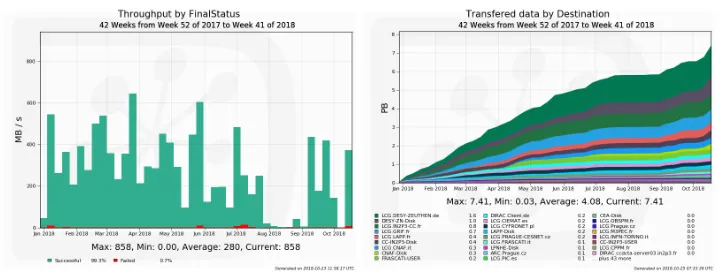
As shown in Figure 1, another significant part of our computing activities this year cor-responds to the reprocessing of our legacy Prod3(b) datasets with the final version of the analysis software in order to get a perfectly coherent view of the instrument performance. Data analysis is very demanding in terms of data access as shown on Figure 2. In 2018, the overall data transfer volume is around 7.4 PB with a corresponding throughput of 200-600 MB/s. The current total storage occupancy has reached about 3.7 PB, distributed in 6 main storage elements. For all data operations we have relied on the DIRAC DMS and the Dirac File Catalog (DFC), that has proven good scalability and flexibility. Today, our DFC contains more than 30 million registered files, about 260 datasets characterized by a dozen meta-data items and has shown no sign of performance limitations.
Figure 2. Left: Throughput during MC campaigns in 2018. Successful transfers are represented in green, while failed transfers are in red. Right: Cumulative data transferred in 2018. In total, more than 7 PB have been transferred. They include all the transfers between the processing sites and the storage locations, both for production and analysis jobs.
The next step in terms of simulations corresponds to specific productions with updated telescope and camera models in order to support the analysis of proposed hardware designs by the CTA Observatory. This is also a preliminary step toward a new large-scale production of instrument response functions with the final telescope and camera designs.
3.2 Production management
To manage and automate as much as possible our large-scale productions we heavily rely on the DIRAC Transformation System (TS). The TS is a data-driven system designed to handle large productions (i.e. typically hundreds of thousands jobs) processing large datasets [6] through the concept of transformation. A transformation is essentially a ‘recipe’ to create jobs plus a ‘filter’ to select input data that jobs must process. The ‘recipe’ contains the job description (i.e. the application to be executed and its parameters) as well as plugins to define how jobs should be distributed among sites and how input files should be grouped. The ‘filter’ is a query on the file meta-data to select the data to be processed by the jobs. The relevant meta-data to characterize the different datasets are defined by the production manager in the DFC. A data-driven mechanism ensures that, as soon as new files matching a transformation filter are registered in the catalog, the corresponding jobs are created.
In practice, for Prod3(b), we typically created a first series of transformations, one per each particle type, running the air shower generation and the telescope simulation to produce level 0 data saved on the grid storage. Then, we created a second series of transformations for the level 1 analysis. Depending mostly upon the readiness of the analysis software, these two sets of transformations were created either sequentially or in parallel, new analysis jobs being created as soon as new level 0 data files were registered in the file catalog.
4 General purpose production system
In order to further automatize this process, many experiments (e.g. LHCb, ILC and Belle II) developed their own specific high-level system on the top of the TS [18]. Inspired by the experience gained by these experiments, we have developed a general purpose workflow system, called the Production System (PS), aimed to be used by several communities beyond CTA.
One of the main requirements for the Production System is the capability to automatically instantiate the different transformations that compose a workflow, later called ‘production’.
Moreover, it should allow the management of a production as a single entity rather than as a set of individual transformations. This includes the possibility to perform global actions (e.g.
status monitor, start, stop, clean, delete) on all the transformations composing a production (‘production transformations’). Finally, the validity of a production should be checked by the system before launching any transformation, i.e. before submitting hundreds of thousands of jobs processing large datasets as in typical productions.
In order to fulfill these requirements, we have developed a data-driven Production System, where transformations are ‘linked’ on the basis of their input and output meta-data character-ization. A production is essentially defined as a set of transformations with their associations (or links). In practice, a production is specified through a ‘description’, consisting of a num-ber of ‘production steps’. Each production step contains the description of a specific trans-formation with the eventual specification of a ‘parent’ production step (i.e. a parent transfor-mation). Two transformations are considered as linked if they have a parent-child relation. In order to support these transformation links, it has been necessary to extend the transformation definition by adding the characterization of the transformation output data through a set of meta-data (similarly to the input data filter). We call ‘Input/OutputMetaQuery’, the query on
the meta-data selecting the input/output data of a transformation. If the OutputMetaQuery of
a transformation logically intersects the InputMetaQuery of another transformation, the first can be declared as parent of the second. A production step can have multiple parents (or no parents) and one or multiple child steps. With these definitions, the PS supports different
types of workflows, i.e. with sequential transformations, with splitting or merging transfor-mations. Starting from the production description, a dedicated utility checks the production validity. A production is considered as valid if the production step descriptions are valid and if the parent-child transformations are linked in the sense specified above.
4.1 Architecture
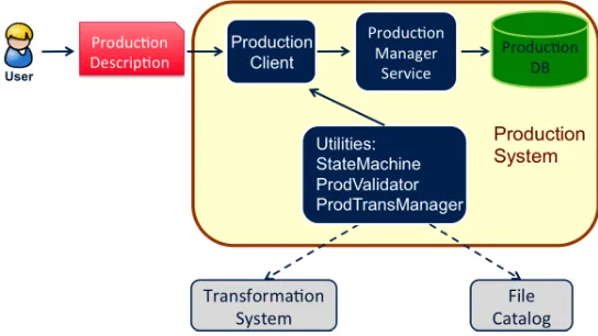
The architecture of the Production System is similar to that of any other DIRAC System and is composed of: 1) the Production database (DB); 2) the Production Manager Service; 3) the Production Client. The Production DB permanently stores the production descriptions and the links between the transformations. It is accessed by the Production Client through the Production Manager Service. Three utilities accomplish specific tasks and interact with the TS and the DFC: 1) ProdValidator; 2) ProdTransManager; 3) StateMachine. The typical be-havior of the PS is schematized in Figure 3. First, the user provides a production description through the Production Client. Then, the ProdValidator utility checks the description validity by verifying the links between the different parent-child production steps. This utility also
interacts with the DFC to ensure that the meta-data used in the Input/OutputMetaQueries are
In order to further automatize this process, many experiments (e.g. LHCb, ILC and Belle II) developed their own specific high-level system on the top of the TS [18]. Inspired by the experience gained by these experiments, we have developed a general purpose workflow system, called the Production System (PS), aimed to be used by several communities beyond CTA.
One of the main requirements for the Production System is the capability to automatically instantiate the different transformations that compose a workflow, later called ‘production’. Moreover, it should allow the management of a production as a single entity rather than as a set of individual transformations. This includes the possibility to perform global actions (e.g.
status monitor, start, stop, clean, delete) on all the transformations composing a production (‘production transformations’). Finally, the validity of a production should be checked by the system before launching any transformation, i.e. before submitting hundreds of thousands of jobs processing large datasets as in typical productions.
In order to fulfill these requirements, we have developed a data-driven Production System, where transformations are ‘linked’ on the basis of their input and output meta-data character-ization. A production is essentially defined as a set of transformations with their associations (or links). In practice, a production is specified through a ‘description’, consisting of a num-ber of ‘production steps’. Each production step contains the description of a specific trans-formation with the eventual specification of a ‘parent’ production step (i.e. a parent transfor-mation). Two transformations are considered as linked if they have a parent-child relation. In order to support these transformation links, it has been necessary to extend the transformation definition by adding the characterization of the transformation output data through a set of meta-data (similarly to the input data filter). We call ‘Input/OutputMetaQuery’, the query on the meta-data selecting the input/output data of a transformation. If the OutputMetaQuery of a transformation logically intersects the InputMetaQuery of another transformation, the first can be declared as parent of the second. A production step can have multiple parents (or no parents) and one or multiple child steps. With these definitions, the PS supports different types of workflows, i.e. with sequential transformations, with splitting or merging transfor-mations. Starting from the production description, a dedicated utility checks the production validity. A production is considered as valid if the production step descriptions are valid and if the parent-child transformations are linked in the sense specified above.
4.1 Architecture
The architecture of the Production System is similar to that of any other DIRAC System and is composed of: 1) the Production database (DB); 2) the Production Manager Service; 3) the Production Client. The Production DB permanently stores the production descriptions and the links between the transformations. It is accessed by the Production Client through the Production Manager Service. Three utilities accomplish specific tasks and interact with the TS and the DFC: 1) ProdValidator; 2) ProdTransManager; 3) StateMachine. The typical be-havior of the PS is schematized in Figure 3. First, the user provides a production description through the Production Client. Then, the ProdValidator utility checks the description validity by verifying the links between the different parent-child production steps. This utility also interacts with the DFC to ensure that the meta-data used in the Input/OutputMetaQueries are well defined. If the description is validated, the corresponding production is inserted into the Production DB, otherwise an error is returned. This mechanism prevents human errors that may occur when the user has to manually create several transformations composing a produc-tion. Once the production is created, the user actually activates it using the Production Client, thus triggering the creation of the corresponding transformations by the ProdTransManager utility. The main actions on productions that are supported by the Production Client are:
start, stop, clean and delete. The ProdTransManager utility manages all the interactions with the TS to perform the corresponding action on the production transformations. Production monitoring is also supported and it consists of getting the status and the progress of all the associated transformations. Finally, the State Machine utility prevents forbidden transitions between different production statuses (for instance a production cannot pass from ‘Stopped’ to ‘New’ status).
Figure 3.Production System software architecture.
4.2 Evolution
The Production System presented in the previous section fulfills the minimum requirements for an efficient workflow management. However so far, only functional tests have been per-formed, so that we expect that useful feedback for improvement will come from its utilization at a larger scale. In particular, we plan to employ the Production System for the next large-scale CTA productions, foreseen in 2019. To facilitate its utilization we have already planned to develop a web interface that would expose the same functionalities currently available through the python API or the command line. Most likely, additional feedback will come from other experiments that may adopt it.
Finally, we have already identified a possible improvement in the logic used to link the different production steps. Indeed, the currently implemented logic supports only relatively simple types of meta-data queries, as those used in most experiments, i.e. consisting of a set of key-value meta-data pairs chained with the logical AND operator. Our plan is to further enhance this logic to support more complex meta-data queries.
5 Conclusions
the DIRAC consortium in order to further develop the core of the system, including improve-ments of the Transformation System [19] and the development of a new general purpose high level Production System.
So far, no significant issue of flexibility or scalability has arisen with any of the DIRAC components that we use. The plan is hence to propose the current DIRAC setup as a prototype for the official CTA Computing Resource Management System, with the exception of the data
management part in the case another solution is proposed. With the Production System almost ready, a major piece still missing in our prototype is a specific system to better handle failed jobs and/or missing data. Indeed, so far, we have run only simulations for which a missing
job or data file is not an issue, but that is clearly not acceptable when processing real data.
We gratefully acknowledge financial support from the agencies and organizations listed here: http://www.cta-observatory.org/consortium_acknowledgments.
References
[1] https://www.egi.eu/
[2] M. Actis et al. (CTA Consortium), Experimental Astronomy,32, 193-316 (2011) [3] A. Casajus et al., Journal of Physics: Conference Series,396, 032107 (2012) [4] F. Stagni et al., Journal of Physics: Conference Series,898, 092020 (2017) [5] J. Blomer et al., Journal of Physics: Conference Series,396, 052013 (2012) [6] L. Arrabito et al., Journal of Physics Conference Series,898, 052013 (2017) [7] https://mariadb.com/kb/en/library/galera-cluster/
[8] A. Andronis et al., Journal of Physics Conference Series,664, 022012 (2015) [9] R.J. Sobie, Journal of Physics Conference Series,664, 022037 (2015) [10] https://www.hnscicloud.eu/
[11] https://www.openstack.org/
[12] http://occi-wg.org/
[13] https://opennebula.org/
[14] F. Stagni et al., Journal of Physics: Conference Series,664, 062061 (2015) [15] http://www.cta-observatory.org/science/cta-performance/
[16] T. Hassan et al., Astroparticle Physics,93(2017)