The PADME Detector
Paola Gianotti
∗on behalf of the PADME collaboration1 ∗Laboratori Nazionali di Frascati dell’INFN
Via E. Fermi 40 I-00044 Frascati (Italy) Email: [email protected]
Abstract—The PADME experiment, by using the positron beam of the Frascati laboratory, aims at searching for signals of a dark photon, A . It will evaluate the final state missing
mass of the process e+ e−→A γ by knowing the beam energy
and measuring the four-momentum of the ordinary recoil photon. The precise determination of this quantity, and the capability to reject background events, are the key points for the success of the experiment. In this paper a description of each component of the PADME detector is given.
I. INTRODUCTION
The Positron Annihilation into Dark Matter Experiment (PADME) [1] aims to search for the production of a dark photon in the process:
e+e− →Aγ (1)
To measure such a reaction, at the Frascati National Laboratory (LNF) of INFN, it is under construction a small scale detector composed of the following parts:
• a diamond active target station, capables to measure the
average position and the intensity of the beam; it also includes a beam monitor device, made of ultra-thin silicon pixel detectors, to study beam characteristics in terms of intensity and divergence;
- a finely segmented, high resolution electromagnetic calorimeter, to measure four-momenta and/or veto final state photons;
- a dipole magnet, to deflect the primary positron beam out of the spectrometer and the calorimeter and to allow momentum analysis;
- a spectrometer, to measure the momenta of the charged particles in the energy range 50-400 MeV;
- a vacuum chamber, to minimize the unwanted interactions of primary and secondary particles;
1G. Chiodini, P. Creti, F. Oliva (INFN Lecce), A.P. Caricato, M. Martino,
G. Maruccio, A. Monteduro, V. Scherini, S.Spagnolo (INFN Lecce e Dip. di Matematica e Fisica, Universit`a del Salento), P. Albicocco, R. Bedogni, B. Buonomo, F. Bossi, R. De Sangro, G. Finocchiaro, L.G. Foggetta, A. Ghigo, P. Gianotti, M. Palutan, G. Piperno, I. Sarra, B. Sciascia, T. Spadaro, E. Spiriti (INFN Laboratori Nazionali di Frascati), L. Tsankov, (University of Sofia ”St. Kl. Ohridski), G. Georgiev, V. Kozhuharov (University of Sofia ”St. Kl. Ohridski” and INFN Laboratori Nazionali di Frascati), F. Ameli, F. Ferrarotto, E. Leonardi, P. Valente (INFN Roma1), S. Fiore (INFN Roma1 e ENEA), G.C.Organtini, M.Raggi (INFN Roma1 e Dip. di Fisica, Sapienza” Universit`a di Roma), C. Taruggi (INFN Laboratori Nazionali di Frascati e Dip. di Fisica, Universit`a di Roma Tor Vergata”)
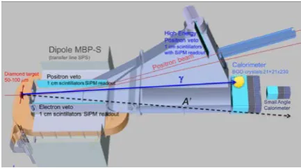
Fig. 1. Layout of the PADME experimental setup (see text for more details).
- a further silicon pixel detector to monitor the not inter-acting positrons.
An overview of the PADME experimental setup can be seen in fig. 1.
The 550 MeV positron beam, provided by the LINAC of the LNF, crosses the diamond target and if it does not interact, it is bent by the dipole in between the end of the spectrometer and the calorimeter. If any kind of interaction causes the positron to lose more than 50 MeV of energy, the magnet bends it into the spectrometer acceptance, where a segmented detector provides a veto signal. In case reaction (1) occurs, the accompanying ordinary photon is detected by the electromagnetic calorimeter regardless of the A decay products. A single kinematic
vari-able characterizing the process, the missing mass, is computed using the formula:
Mmiss2 = (−→Pbeam+−→Pe−−−→Pγ)2 (2)
with the target electrons assumed to be at rest (−→Pe− =−→0) while for the beam a nominal momentum of 550 MeV along the z axis is expected. The distribution of this variable should peak at M2
A if an A is produced, at zero for the concurrent e+e−→γγ process, and should be smooth for the remaining
Fig. 2. Montecarlo simulated squared missing mass for background events. In red with no selection cuts, in blue after all cuts are applied. If a dark photon Ais produced it should manifest as a pick in this distribution at the proper
mass.
- no signals in the veto counters.
In this way, a sensitivity better than 10−3 can be reached on
the couplingεof the dark photon in a mass range up to≈23
MeV/c2 [2].
In order to perform at best this measurement, each element of the experimental setup has specific requirements that are stringent and sometimes challenging. In the following sections, it is given a description of the chosen technical solutions implemented to accomplish the experiment needs. Results of the test beams, performed to characterize each sub-component, are also illustrated.
II. THE TARGET STATION
To enhance the dark photon signal, proportional to the annihilation cross-section (∝ Z), with respect to the Bremsstrahlung background (∝ Z2), a low Z material is
needed. Carbon is the right compromise. In addition, the target should be thin enough to reduce the number of pile-up events to a level manageable by the high-energy resolution electromagnetic calorimeter. The knowledge of the beam spot hitting the target can improve the missing mass resolution, thus increasing the statistical significance of the signal. The above requirements can be satisfied by an active target made of detector-grade polycrystalline CVD diamond with strip electrodes on both sides and connected to adequate front-end electronics. Two active target prototypes (2×2 cm2 area and
50 and 100µm thickness) have been built and characterized
with high multiplicity electron bunches at the Frascati Beam Test Facility (BTF) [3]. The readout strips (1 mm pitch in orthogonal directions on the two sides of the film) were made in the first case with in-house laser graphitization, in the second case with Cr-Au thermal evaporation by the supplier. The prototype with graphitic electrodes was fully characterized with two kind of off-board electronics, showing a good position resolution (∼0.2 mm) on both views and timing performance (∼ 2 ns) meeting the requirement of PADME. The prototype with Cr-Au electrodes was readout with the
Fig. 3. Beam spot obtained with the MIMOSA sensors at the Frascati BTF.
Fig. 4. CAD drawing of the target station: it houses either the thin diamond target and a beam monitoring system, based on monolithic silicon pixel detectors. Both components are remotely movable via a step motor.
on-board final electronics showing very good signal-to-noise ratio, but full characterization was impossible due to a poor quality of the contacts likely due to a not careful deposition [4].
To have a more accurate beam monitor capability, in the target region will be installed a system based on two planes of silicon pixel detectors placed up and down stream the diamond target. Each plane will consist of two MIMOSA 28 Ultimate chips, developed for the upgrade of the STAR vertex detector [5]. These devices integrate a Monolithic Active Pixel Sensor (MAPS) with a fast binary readout. Each sensor consists of a matrix of 928×960 pixels of 20.7µm with a thickness of 50µm. For the STAR experiment the chips, that dissipate 150 mW/cm2, operate in air without cooling. For PADME, the
detectors should be placed in vacuum and a modified PCB is under development at the LNF electronic workshop. A first prototype of this new monitoring system has been tested on the beam in April 2017. The picture of the BTF electron beam spot, obtained with the MIMOSA detectors, is visible in fig 3. Figure 4 shows a CAD drawing of the target region. Both the target and the beam monitor will be connected to step motors to allow their insertion in and out from the beam line.
III. THE DIPOLE MAGNET
The positron beam of 103/104 particles/pulse (depending
mainly from beam pulse duration and the pile-up rate) will pass almost undisturbed through the PADME thin Carbon
target. Therefore, a magnetic field of a moderate strength (∼ 0.5 T) is necessary to sweep it out from the acceptance of the e.m. calorimeter. A magnet with the requested characteristics has been found at CERN within the spare dipoles of the SPS transport line (MBP-S), and it has been shipped to LNF at the end of 2015. During 2016, the dipole vertical gap has been increased to 230 mm, to better suite the experiment needs, and a campaign of measurements to map the field has been performed.
Figure 5 shows a picture of the magnet and the plots of the field map measurements. The magnet will house a vacuum vessel of proper shape hosting a segmented charged particle veto system
IV. THE VETO TRACKING SYSTEM
The Bremsstrahlung is the process with the highest cross section, when the positron beam interact with the target. This leads to the production of low energy photons emitted mostly at small angles. To cut out these events, the main e.m. calorimeter has been designed with a central hole, with an aperture of∼1o, and a fast, Small Angle Calorimeter (SAC), is placed behind to generate a corresponding veto signal. Furthermore, the magnetic field will deflect the charged tracks proportionally to their momentum. Strips of plastic scintillators (10×10×180 mm3), readout by SiPMs, will cover both sides
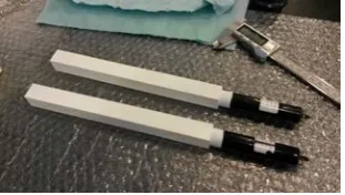
of the dipole gap, with the long side aligned to the magnetic field (y axis), while others will be located in the forward region outside the magnet (see fig. 1). A rough measurement of the momentum of the particles will be obtained from the position of the hit (∼%). A prototype of these veto detectors is shown in Fig. 6 taken during a test, performed in April 2017, with an electron beam of 500 MeV. It consists of 16 plastic scintillator strips white painted, to better diffuse the scintillating light, readout by SiPMs Hamamatsu S13360 [8] mounted on a PCB developed by Frascati electronic service providing also signal amplification and shaping. The analog signals are then pro-cessed by CAEN V1742 high-speed digitizers [9], based on the DRS4 chip, set to a sampling speed of 5 GS/s (200 ps/sample). The light can be readout directly from the scintillator coupled to the SiPM, or through a WLS fiber placed in a groove along the bar in contact with the SiPM. During the test beam, the different possibilities have been tested. Preliminary results seem to indicate a better performance of the readout performed via the WLS fiber. An average time resolution of about 600 ps has been measured, while the detection efficiency is >0.998
for all slabs.
V. THE ELECTROMAGNETIC CALORIMETER
The most important detector of the PADME setup is the electromagnetic calorimeter that should evaluate with high ef-ficiency the energy, direction and timing of the single photons emitted from the target. The requirements for this detector are:
- high acceptance for ordinary photons; - energy resolution<2 %/√E GeV;
- time resolution∼0.5 ns; - angular resolution∼1÷2 mrad.
To cut out the high number of Bremsstrahlung photons pro-duced in the interaction with the target, the main calorimeter (ECAL) will have a central hole, and behind this, a second, small size and faster calorimeter (SAC), will be placed. The ECAL module, placed 3 m downstream the target, is a tight matrix of 616 crystals (21×21×230 mm3) arranged in a
cylinder of external radius 30 cm, with a squared central hole of 10 cm (see fig. 7). This arrangement allow a 66% acceptance for a 550 MeV positron beam. The choice of the scintillating material for the ECAL has been driven by different aspects: high density, small radiation length and Molire radius (due to the calorimeter small dimensions), high light output (due to the low energy range), cost. Excluding the cost requirement, both LYSO and BGO would have been suitable, with a slight preference for the LYSO since it has a shorter decay time that would have mitigated the effect of event pile-up caused by the beam structure. Nevertheless, the BGO crystals that were used by the L3 experiment at LEP [6], that are property of INFN, were available at the only cost of cutting them at the proper size. Therefore, after having checked that these crystals could be reconditioned and re-shaped, they have been adopted.
For the light collection, early tests, aimed at evaluating the best readout technology, showed that avalanche photodiodes (APDs), even with a relatively large area of 10×10 mm2,
have a gain that is insufficient to perform a high resolution energy measurement in the PADME energy rage (from a few to a few hundred MeV). The readout system will therefore be based on 19 mm diameter photomultipliers. On July 2016, XP1912 HZC Photonics tubes [7] have been tested at the BTF, on a calorimeter prototype made of 25 BGO crystals obtained by machining the L3 recovered ones. Figure 8 shows two units of the ECAL detector. The 25 channels of the prototype were readout by a CAEN V1742 high-speed digitizer [9] set to a sampling speed of 1 GS/s (1 ns/sample). An important feature of the BTF facility is the possibility to vary the beam intensity from 109particles down to a single particle per pulse.
Electrons of two different energies, 250 and 450 MeV, were fired on the ECAL prototype in order to evaluate the energy resolution. The results are shown in fig. 9 [10].
To reject backgrounds with multiple photons in the final state, namely e+e− → γγ and e+e− → γγγ, 50 cm
downstream the hole of the main ECAL a fast Small Angle Calorimeter (SAC) is foreseen. The requirements for this detector are:
- good energy resolution and efficiency for photon in the 100 MeV energy range;
- capability to sustain high rates; - time resolution of about 200 ps;
- radiation hardness up to 1 Gy per 1013positrons on target.
Among inorganic crystals commonly used for e.m. calorime-ters, only Barium Fluouride (BaF2), having a fast component
Fig. 2. Montecarlo simulated squared missing mass for background events. In red with no selection cuts, in blue after all cuts are applied. If a dark photon Ais produced it should manifest as a pick in this distribution at the proper
mass.
- no signals in the veto counters.
In this way, a sensitivity better than 10−3 can be reached on
the couplingεof the dark photon in a mass range up to≈23
MeV/c2 [2].
In order to perform at best this measurement, each element of the experimental setup has specific requirements that are stringent and sometimes challenging. In the following sections, it is given a description of the chosen technical solutions implemented to accomplish the experiment needs. Results of the test beams, performed to characterize each sub-component, are also illustrated.
II. THE TARGET STATION
To enhance the dark photon signal, proportional to the annihilation cross-section (∝ Z), with respect to the Bremsstrahlung background (∝ Z2), a low Z material is
needed. Carbon is the right compromise. In addition, the target should be thin enough to reduce the number of pile-up events to a level manageable by the high-energy resolution electromagnetic calorimeter. The knowledge of the beam spot hitting the target can improve the missing mass resolution, thus increasing the statistical significance of the signal. The above requirements can be satisfied by an active target made of detector-grade polycrystalline CVD diamond with strip electrodes on both sides and connected to adequate front-end electronics. Two active target prototypes (2×2 cm2 area and
50 and 100µm thickness) have been built and characterized
with high multiplicity electron bunches at the Frascati Beam Test Facility (BTF) [3]. The readout strips (1 mm pitch in orthogonal directions on the two sides of the film) were made in the first case with in-house laser graphitization, in the second case with Cr-Au thermal evaporation by the supplier. The prototype with graphitic electrodes was fully characterized with two kind of off-board electronics, showing a good position resolution (∼0.2 mm) on both views and timing performance (∼ 2 ns) meeting the requirement of PADME. The prototype with Cr-Au electrodes was readout with the
Fig. 3. Beam spot obtained with the MIMOSA sensors at the Frascati BTF.
Fig. 4. CAD drawing of the target station: it houses either the thin diamond target and a beam monitoring system, based on monolithic silicon pixel detectors. Both components are remotely movable via a step motor.
on-board final electronics showing very good signal-to-noise ratio, but full characterization was impossible due to a poor quality of the contacts likely due to a not careful deposition [4].
To have a more accurate beam monitor capability, in the target region will be installed a system based on two planes of silicon pixel detectors placed up and down stream the diamond target. Each plane will consist of two MIMOSA 28 Ultimate chips, developed for the upgrade of the STAR vertex detector [5]. These devices integrate a Monolithic Active Pixel Sensor (MAPS) with a fast binary readout. Each sensor consists of a matrix of 928×960 pixels of 20.7µm with a thickness of 50µm. For the STAR experiment the chips, that dissipate 150 mW/cm2, operate in air without cooling. For PADME, the
detectors should be placed in vacuum and a modified PCB is under development at the LNF electronic workshop. A first prototype of this new monitoring system has been tested on the beam in April 2017. The picture of the BTF electron beam spot, obtained with the MIMOSA detectors, is visible in fig 3. Figure 4 shows a CAD drawing of the target region. Both the target and the beam monitor will be connected to step motors to allow their insertion in and out from the beam line.
III. THE DIPOLE MAGNET
The positron beam of 103/104 particles/pulse (depending
mainly from beam pulse duration and the pile-up rate) will pass almost undisturbed through the PADME thin Carbon
target. Therefore, a magnetic field of a moderate strength (∼ 0.5 T) is necessary to sweep it out from the acceptance of the e.m. calorimeter. A magnet with the requested characteristics has been found at CERN within the spare dipoles of the SPS transport line (MBP-S), and it has been shipped to LNF at the end of 2015. During 2016, the dipole vertical gap has been increased to 230 mm, to better suite the experiment needs, and a campaign of measurements to map the field has been performed.
Figure 5 shows a picture of the magnet and the plots of the field map measurements. The magnet will house a vacuum vessel of proper shape hosting a segmented charged particle veto system
IV. THE VETO TRACKING SYSTEM
The Bremsstrahlung is the process with the highest cross section, when the positron beam interact with the target. This leads to the production of low energy photons emitted mostly at small angles. To cut out these events, the main e.m. calorimeter has been designed with a central hole, with an aperture of∼1o, and a fast, Small Angle Calorimeter (SAC), is placed behind to generate a corresponding veto signal. Furthermore, the magnetic field will deflect the charged tracks proportionally to their momentum. Strips of plastic scintillators (10×10×180 mm3), readout by SiPMs, will cover both sides
of the dipole gap, with the long side aligned to the magnetic field (y axis), while others will be located in the forward region outside the magnet (see fig. 1). A rough measurement of the momentum of the particles will be obtained from the position of the hit (∼%). A prototype of these veto detectors is shown in Fig. 6 taken during a test, performed in April 2017, with an electron beam of 500 MeV. It consists of 16 plastic scintillator strips white painted, to better diffuse the scintillating light, readout by SiPMs Hamamatsu S13360 [8] mounted on a PCB developed by Frascati electronic service providing also signal amplification and shaping. The analog signals are then pro-cessed by CAEN V1742 high-speed digitizers [9], based on the DRS4 chip, set to a sampling speed of 5 GS/s (200 ps/sample). The light can be readout directly from the scintillator coupled to the SiPM, or through a WLS fiber placed in a groove along the bar in contact with the SiPM. During the test beam, the different possibilities have been tested. Preliminary results seem to indicate a better performance of the readout performed via the WLS fiber. An average time resolution of about 600 ps has been measured, while the detection efficiency is >0.998
for all slabs.
V. THE ELECTROMAGNETIC CALORIMETER
The most important detector of the PADME setup is the electromagnetic calorimeter that should evaluate with high ef-ficiency the energy, direction and timing of the single photons emitted from the target. The requirements for this detector are:
- high acceptance for ordinary photons; - energy resolution <2 %/√E GeV;
- time resolution∼0.5 ns; - angular resolution∼1÷2 mrad.
To cut out the high number of Bremsstrahlung photons pro-duced in the interaction with the target, the main calorimeter (ECAL) will have a central hole, and behind this, a second, small size and faster calorimeter (SAC), will be placed. The ECAL module, placed 3 m downstream the target, is a tight matrix of 616 crystals (21×21×230 mm3) arranged in a
cylinder of external radius 30 cm, with a squared central hole of 10 cm (see fig. 7). This arrangement allow a 66% acceptance for a 550 MeV positron beam. The choice of the scintillating material for the ECAL has been driven by different aspects: high density, small radiation length and Molire radius (due to the calorimeter small dimensions), high light output (due to the low energy range), cost. Excluding the cost requirement, both LYSO and BGO would have been suitable, with a slight preference for the LYSO since it has a shorter decay time that would have mitigated the effect of event pile-up caused by the beam structure. Nevertheless, the BGO crystals that were used by the L3 experiment at LEP [6], that are property of INFN, were available at the only cost of cutting them at the proper size. Therefore, after having checked that these crystals could be reconditioned and re-shaped, they have been adopted.
For the light collection, early tests, aimed at evaluating the best readout technology, showed that avalanche photodiodes (APDs), even with a relatively large area of 10×10 mm2,
have a gain that is insufficient to perform a high resolution energy measurement in the PADME energy rage (from a few to a few hundred MeV). The readout system will therefore be based on 19 mm diameter photomultipliers. On July 2016, XP1912 HZC Photonics tubes [7] have been tested at the BTF, on a calorimeter prototype made of 25 BGO crystals obtained by machining the L3 recovered ones. Figure 8 shows two units of the ECAL detector. The 25 channels of the prototype were readout by a CAEN V1742 high-speed digitizer [9] set to a sampling speed of 1 GS/s (1 ns/sample). An important feature of the BTF facility is the possibility to vary the beam intensity from 109particles down to a single particle per pulse.
Electrons of two different energies, 250 and 450 MeV, were fired on the ECAL prototype in order to evaluate the energy resolution. The results are shown in fig. 9 [10].
To reject backgrounds with multiple photons in the final state, namely e+e− → γγ and e+e− → γγγ, 50 cm
downstream the hole of the main ECAL a fast Small Angle Calorimeter (SAC) is foreseen. The requirements for this detector are:
- good energy resolution and efficiency for photon in the 100 MeV energy range;
- capability to sustain high rates; - time resolution of about 200 ps;
- radiation hardness up to 1 Gy per 1013positrons on target.
Among inorganic crystals commonly used for e.m. calorime-ters, only Barium Fluouride (BaF2), having a fast component
(a) Picture of the PADME dipole. The used coordinate
system is also indicated. (b) Longitudinal scan of the magnetic field at differenttransverse positions. Fig. 5. The PADME dipole magnet.
Fig. 6. Prototype of the veto detector ready for a beam test. The electronic cards at the bottom house SiPMs that collect the light generated in the plastic scintillators.
Fig. 7. Layout of the PADME main e.m. calorimeter (ECAL). it consists of an array of 616 BGO crystals.
Fig. 8. Two units of the PADME ECAL detector. They consist of a BGO crystal (10×10×230 mm3) glued to a 19 mm diameter photomultiplier.
Energy (MeV)
200 400 600 800 1000 1200
(E)/E
σ
0.01 0.015 0.02 0.025 0.03 0.035 0.04
/ ndf
2
χ 4.798 / 4 a 0.02041 ± 7.478e-05 c 0.0112 ± 0.0002927
Fig. 9. Energy resolution measured with a prototype of the PADME ECAL at the Frascati BTF. Red and blue points refer to two different beam energies of 450 and 250 MeV, respectively. The line is the best fit curve whose parameters are quoted in the inset.
TABLE I
MAIN CHARACTERISTICS OF THE CRYSTALS UNDER STUDY FOR THE
PADME SMALLANGLECALORIMETER.
PbF2 SF57 Density[g/cm3] 7.77 5.51
X0[cm] 0.93 1.54
Moliere radius[cm] 2.12 2.61 Interaction length (λ)[cm] 22.1 20.6
λ/X0 23.65 13.3
Refraction index 1.8 1.8
toward Cherenkov emitting crystals. Lead glasses (Schott SF57) used by the OPAL experiment at CERN, are available at Frascati. Another Cherenkov counter that can match even better the needs of the experiment is Lead Fluouride (PbF2).
It owns a higher density, a better λ/X0 ratio that imply more compact showers; better transparency down to∼250 nm, and a factor 10 more radiation hardness with respect to SF57. Table I shows the main characteristics of both SF57 and PbF2
materials.
In order to have a good timing response, for the photosen-sors, fast photomultipliers are mandatory. With a SF57 crystal, read out with Hamamatsu R9880-U100 PM [8], exposed in November 2016 to the BTF electron beam, a RMS of 600 ps in the time resolution was achieved. In April 2017, two samples of PbF2, used by theg−2 collaboration at Fermilab
to build their e.m. calorimeter (30×30×150 mm3), have been
shipped to Frascati. They have been coupled to the same PMs Hamamatsu and exposed to the BTF beam, together with the SF57 crystal, to compare their behaviours. The data analysis is still ongoing, but the preliminary results indicate that PbF2
coupled with a PM with a larger, 1 inch diameter photocath-ode (i.e. R13478), could reach the experiment requirements. Further tests will be then performed during summer.
The final layout of the calorimeter will consist in a squared matrix of crystals whose number will depend from the cho-sen material. The two possible alternatives are: a 7×7 ar-ray of 20×20×200 mm3 SF57 crystals, or a 5
×5 array of 30×30×150 mm3 PbF
2 ones.
VI. BEAM MONITOR
As already mentioned, a big fraction of the incoming positrons will cross the diamond target without interacting, and the dipole magnet will deflect them out of the calorimeters acceptance. By placing a silicon pixel detector immediately out of the vacuum vessel, it would be possible to precisely monitor online the beam characteristics. A device, based on the Timepix3 chip [11], can be the perfect solution.
The Timepix chip family are conceived for timing mea-surements with the added functionality of measuring time-over-threshold, these features are perfect for particle tracking applications where timing and spatial resolution are necessary. The device can be operated in different mode allowing to acquire charge and time, time only, event counting and integral charge. The time resolution is ∼ 1.5 ns and it can stands particle rates up to 40 Mhits/cm2/s.
Many tracking detectors based on the Timepix3 chip have been developed for particle physics apparatuses. PADME need to build a Timepix array covering an area of 10×3 cm2. At
present, the collaboration is considering the offers of NIKHEF and Diamond laboratories which both can provide detectors that can be easily adapted to the experiment setup.
VII. TIMELINE ANDCONCLUSION
After the approval at the end of 2015, an international collaboration has been formed to perform the PADME experi-ment. At present, it consists of about 50 people from 8 differ-ent institutions: INFN Lecce, Saldiffer-ento University, INFN LNF, University and INFN Roma, University of Sofia, MTA Atomki from Hungary, William and Mary College of Williamsburg (VA), Cornell University of Ithaca (NY) last two both from USA. The collaboration with Cornell is also looking to the future. In facts, at this Institute there are plans to realize an extracted positron beam line, from the CESR storage ring, of 5.3 GeV on which, an upgraded version of the PADME
experiment could be installed. This will extend the region of possible mass of the dark photon search.
At present, the design of the PADME detector elements has been completed in almost all aspects, and the procurement of the main components has already started in 2016. The different sub-detectors are under construction and the installation on the beam line is foreseen for winter 2017. After a commissioning of few weeks in spring 2018, the real data taking of the experiment could start.
In order to achieve 1013positrons on target in a six months
data taking period, the Frascati LINAC has to be slightly modified and optimized to increase the positron pulse duration from the present value of 40 ns to 250 ns. During 2016 a new LINAC pulsing system has been installed, and dedicated machine development runs have been performed to stretch the pulse duration. Further adjustments are foreseen in 2017 to reduce the intensity variations and to keep the beam energy spread below 2%.
ACKNOWLEDGMENT
The authors would like to thanks MAECI that partially support this activity throughout the PGR-226 grant.
REFERENCES
[1] M. Raggi and V. Kozhuarov, Adv. High Energy Phys. 2014, 959802 (2014).
[2] The PADME collaboration, “The PADME experiment Technical Pro-posal”,
[3] P. Valenteet al., arXiv:1603.05651.
[4] G. Chiodiniet al., JINST 12, C02036 (2017). [5] I. Valinet al., JINST 7, C01102 (2012).
[6] B. Adevaet al., Nucl. Instrum. Meth. A 289, 35 (1990). [7] http://hzcphotonics.com.
[8] http://www.hamamatsu.com
[9] CAEN Mod. 1742, Technical Information Manual, rev6, 06 February 2016.
(a) Picture of the PADME dipole. The used coordinate
system is also indicated. (b) Longitudinal scan of the magnetic field at differenttransverse positions. Fig. 5. The PADME dipole magnet.
Fig. 6. Prototype of the veto detector ready for a beam test. The electronic cards at the bottom house SiPMs that collect the light generated in the plastic scintillators.
Fig. 7. Layout of the PADME main e.m. calorimeter (ECAL). it consists of an array of 616 BGO crystals.
Fig. 8. Two units of the PADME ECAL detector. They consist of a BGO crystal (10×10×230 mm3) glued to a 19 mm diameter photomultiplier.
Energy (MeV)
200 400 600 800 1000 1200
(E)/E
σ
0.01 0.015 0.02 0.025 0.03 0.035 0.04
/ ndf
2
χ 4.798 / 4 a 0.02041 ± 7.478e-05 c 0.0112 ± 0.0002927
Fig. 9. Energy resolution measured with a prototype of the PADME ECAL at the Frascati BTF. Red and blue points refer to two different beam energies of 450 and 250 MeV, respectively. The line is the best fit curve whose parameters are quoted in the inset.
TABLE I
MAIN CHARACTERISTICS OF THE CRYSTALS UNDER STUDY FOR THE
PADME SMALLANGLECALORIMETER.
PbF2 SF57 Density[g/cm3] 7.77 5.51
X0 [cm] 0.93 1.54
Moliere radius[cm] 2.12 2.61 Interaction length (λ)[cm] 22.1 20.6
λ/X0 23.65 13.3
Refraction index 1.8 1.8
toward Cherenkov emitting crystals. Lead glasses (Schott SF57) used by the OPAL experiment at CERN, are available at Frascati. Another Cherenkov counter that can match even better the needs of the experiment is Lead Fluouride (PbF2).
It owns a higher density, a betterλ/X0 ratio that imply more compact showers; better transparency down to∼250 nm, and a factor 10 more radiation hardness with respect to SF57. Table I shows the main characteristics of both SF57 and PbF2
materials.
In order to have a good timing response, for the photosen-sors, fast photomultipliers are mandatory. With a SF57 crystal, read out with Hamamatsu R9880-U100 PM [8], exposed in November 2016 to the BTF electron beam, a RMS of 600 ps in the time resolution was achieved. In April 2017, two samples of PbF2, used by theg−2 collaboration at Fermilab
to build their e.m. calorimeter (30×30×150 mm3), have been
shipped to Frascati. They have been coupled to the same PMs Hamamatsu and exposed to the BTF beam, together with the SF57 crystal, to compare their behaviours. The data analysis is still ongoing, but the preliminary results indicate that PbF2
coupled with a PM with a larger, 1 inch diameter photocath-ode (i.e. R13478), could reach the experiment requirements. Further tests will be then performed during summer.
The final layout of the calorimeter will consist in a squared matrix of crystals whose number will depend from the cho-sen material. The two possible alternatives are: a 7×7 ar-ray of 20×20×200 mm3 SF57 crystals, or a 5
×5 array of 30×30×150 mm3 PbF
2 ones.
VI. BEAM MONITOR
As already mentioned, a big fraction of the incoming positrons will cross the diamond target without interacting, and the dipole magnet will deflect them out of the calorimeters acceptance. By placing a silicon pixel detector immediately out of the vacuum vessel, it would be possible to precisely monitor online the beam characteristics. A device, based on the Timepix3 chip [11], can be the perfect solution.
The Timepix chip family are conceived for timing mea-surements with the added functionality of measuring time-over-threshold, these features are perfect for particle tracking applications where timing and spatial resolution are necessary. The device can be operated in different mode allowing to acquire charge and time, time only, event counting and integral charge. The time resolution is ∼ 1.5 ns and it can stands particle rates up to 40 Mhits/cm2/s.
Many tracking detectors based on the Timepix3 chip have been developed for particle physics apparatuses. PADME need to build a Timepix array covering an area of 10×3 cm2. At
present, the collaboration is considering the offers of NIKHEF and Diamond laboratories which both can provide detectors that can be easily adapted to the experiment setup.
VII. TIMELINE ANDCONCLUSION
After the approval at the end of 2015, an international collaboration has been formed to perform the PADME experi-ment. At present, it consists of about 50 people from 8 differ-ent institutions: INFN Lecce, Saldiffer-ento University, INFN LNF, University and INFN Roma, University of Sofia, MTA Atomki from Hungary, William and Mary College of Williamsburg (VA), Cornell University of Ithaca (NY) last two both from USA. The collaboration with Cornell is also looking to the future. In facts, at this Institute there are plans to realize an extracted positron beam line, from the CESR storage ring, of 5.3 GeV on which, an upgraded version of the PADME
experiment could be installed. This will extend the region of possible mass of the dark photon search.
At present, the design of the PADME detector elements has been completed in almost all aspects, and the procurement of the main components has already started in 2016. The different sub-detectors are under construction and the installation on the beam line is foreseen for winter 2017. After a commissioning of few weeks in spring 2018, the real data taking of the experiment could start.
In order to achieve 1013positrons on target in a six months
data taking period, the Frascati LINAC has to be slightly modified and optimized to increase the positron pulse duration from the present value of 40 ns to 250 ns. During 2016 a new LINAC pulsing system has been installed, and dedicated machine development runs have been performed to stretch the pulse duration. Further adjustments are foreseen in 2017 to reduce the intensity variations and to keep the beam energy spread below 2%.
ACKNOWLEDGMENT
The authors would like to thanks MAECI that partially support this activity throughout the PGR-226 grant.
REFERENCES
[1] M. Raggi and V. Kozhuarov, Adv. High Energy Phys. 2014, 959802 (2014).
[2] The PADME collaboration, “The PADME experiment Technical Pro-posal”,
[3] P. Valenteet al., arXiv:1603.05651.
[4] G. Chiodiniet al., JINST 12, C02036 (2017). [5] I. Valinet al., JINST 7, C01102 (2012).
[6] B. Adevaet al., Nucl. Instrum. Meth. A 289, 35 (1990). [7] http://hzcphotonics.com.
[8] http://www.hamamatsu.com
[9] CAEN Mod. 1742, Technical Information Manual, rev6, 06 February 2016.