INTERACTIVE
FORM CREATION
Exploring the creation and manipulation of free form through the use of interactive multiple input interface.
A v a J . F a t a h g e n a n n t S c h i e c k September 2001
This thesis is submitted in partial fulfilment of the requirements for the degree of Master of Science in Virtual Environments from the University of London
Acknowledgments
I would like to thank my supervisor, Alan Penn, for his advise and support during the course of this research.
I am grateful to Chiron Mottram for his extensive aid concerning the programming part at critical moments during the research.
I would like to thank Alasdair Turner, who provided prompt advice on the programming part.
I thank Lesley Gavin for her support.
For consultation and technical help concerning the computer systems, I thank Usah Hamuth.
I also thank Jesper Mortensen for the demonstration of the PHANTOM haptic device and theDistributed Interactive Virtual Environment DIVE.
Finally I would like to thank Juan Pablo Hourcade, of the (HCIL) at the University of Maryland, for encouraging me to use the MID Library, and for his advice concerning the
‘Historical accident has kept programmers in control of field in which they have no aptitude: the artistic integration of the mechanisms they work with. It is nice that engineers, programmers and software executives have found a new form of creativity in which to find a sense of personal fulfilment. It's just unfortunate that they have to inflict the results on the users.’ Theodor Nelson
‘Since humans are more pliable than computers, it can be easier to make a human fit the computer’s limitations than to design the computer to fit the human’s needs. When that happens, the human becomes a prisoner trapped by the computer rather than liberated by it. ’ Karla Jennings
Abstract
Most current CAD systems support only the two most common input devices: a mouse and a keyboard that impose a limit to the degree of interaction that a user can have with the system. However, it is not uncommon for users to work together on the same computer during a collaborative task. Beside that, people tend to use both hands to manipulate 3D objects; one hand is used to orient the object while the other hand is used to perform some operation on the object. The same things could be applied to computer modelling in the conceptual phase of the design process. A designer can rotate and position an object with one hand, and manipulate the shape [deform it] with the other hand. Accordingly, the 3D object can be easily and intuitively changed through interactive manipulation of both hands.
The research investigates the manipulation and creation of free form geometries through the use of interactive interfaces with multiple input devices.
First the creation of the 3D model will be discussed; several different types of models will be illustrated. Furthermore, different tools that allow the user to control the 3D model interactively will be presented. Three experiments were conducted using different interactive interfaces; two bimanual techniques were compared with the conventional one-handed approach. Finally it will be demonstrated that the use of new and multiple input devices can offer many opportunities for form creation. The problem is that few, if any, systems make it easy for the user or the programmer to use new input devices.
Keywords
T a b l e o f C o n t e n t s
Chapter 1 – Introduction ... 6
1.1 The role of computer in the design process...6
1.2 The use of modelling in the design process ...6
Free form modelling...7
1.3 Human computer interaction HCI ...7
Interface design ...7
1.4 Interaction with computer systems ...8
Direct manipulation ...8
1.5 Input/Output channels ...8
1.5.1 Interactive input devices ...8
Interaction techniques...9
2D pointing devices ...9
Positioning in 3D space ...10
1.5.2 Output devices...11
Visual output device ...11
Haptic output devices ...12
1.5.3 Novel pointing devices...12
1.5.4 Using multiple interaction devices ...12
Chapter 2 – Related Work ... 13
2.1 IDEATE Research Projects ...13
2.2 Designing Storytelling Technologies...14
Chapter 3 – Research Objective ... 15
3.1 Statement of research problem ...15
3.2 Research objective ...15
Chapter 4 – Methodology... 16
4.1 Tools used in the project ... 16
4.2 The process... 16
4.3 The effect of the surface properties variable on the created form... 18
Randomness... 19
4.4 Subjects ... 20
4.5 Establishing independent variables ... 20
4.6 Models ...20
4.6.1 The first model ...20
Experimental set-up...20
Results...21
Interaction devices...21
Surface properties variable...22
4.6.2 The second model ...25
Goal ...25
Experimental set-up...25
Results...26
Interaction devices...26
Surface properties variable...27
4.6.3 The third model...29
Goal ...29
Experimental set-up...29
Input device and user control...30
Results...30
Interaction devices...30
Surface properties variable...32
Chapter 5 – Discussion... 35
Chapter 6 – Conclusion ... 38
Bibliography ... 40
C h a p t e r 1 – I n t r o d u c t i o n
The field of computer graphics has developed significantly in the last several years. The ever-increasing speed of computers in recent years has led to the proliferation of tools for creating and manipulating 3D graphics.
However, even with the tremendous advances in computing technology, users of computing systems are still, in many cases, related to the role of passive observer of data. Furthermore, the input devices that we use to interact with computing systems are limited, providing us with unnatural ways in which to interact with screen displayed objects.
1.1 The role of computer in the design process
Although the computer is widely used in the design process. It is considered most of the time either as a rendering tool for presentation or as a fast drafting tool for technical drawings in two dimensions. Current CAD systems mainly support the preliminary and detailed design phases but fail to support conceptual design. Traditionally large sculptures or even car bodies were first made as small clay models, which were measured and enlarged. Now much of this work is done using computers employing software written for the automobile and aerospace industries. The architect Frank Gehry for example uses aerospace software, but the starting point is still the physical models. For the Guggenheim Museum in Bilbao, paper models and clay models were first constructed, and then they were converted into usable geometrical information through a three-dimensional digital scanner [Van Bruggen 97]. As Gribnau [99] pointed out, the digitising process takes time and is open to interpretation faults, whereas using the CAD system in the early stages will prevent the digitised model from differing from the intention of the designer. Currently after creating a preliminary design on paper and in a scale model a designer typically translate his/her design to strict and exact representation of design in CAD programs, which demands a lot of time and effort.
As Gribnau [99] stated, if the computer is introduced at the conceptual phase several advantages can be gained. The designer can generate more alternatives of a design. On the other hand using computer supported modelling at the conceptual phase will support the integration with the lateral phases of the design process and offer many advantages including ease of transformation, archival, replication and distribution and make it possible to create forms without the limitation of real world material [Gribnau 99]. However, current systems do not allow for the quick and interactive generation and development of objects, which make them insufficient for the early stages of the design process.
1.2 The use of modelling in the design process
Modelling is an active creative process in which the form is evolving Architects use sketching and modelling to create and modify design concepts. Through modelling the designer is actively designing, the activity is interwoven with the creation of ideas and assessment of 3D forms. For quick modelling, designers use a wide range of materials, such as cardboard, plaster, clay and wood. In most cases, a different set of tools is available for each material; each of the tools is optimised for a certain action or form creation. As Gribnau [99] pointed out, there are two general approaches to quick modelling:
The carving away approach: the designer usually starts with a solid material such as clay or foam, parts are cut away or added to the form by using simple tools. This is represented in CAD by solid modelling.
Free form modelling
The major conceptual change which has taken place since the development of the early CAD supported modelling systems, according to Rooney and Steadman [87], lies in the modern use of parametrically defined geometry that has largely replaced the applying classical geometry expressed in terms of conventional Cartesian coordinates. One of the their most important features is that the mathematical formulation of curves and surfaces defined parametrically does not change under transformations such as reflection, rotation or translation. All that changes is a set of numerical coefficients. ‘Ways have been devised of providing coefficients to allow the designer to take advantage of the freedom available in design with no requirement for advanced mathematical training’ [Rooney and Steadman 87].
Figure 1
As Gain [96] pointed out, the modelling system must be measured continuously during the construction of a free form against three criteria:
Intuitively: The user should be able to apply insight from everyday tasks to an unfamiliar modelling environment.
Interactivity: The response-time of the system should be such that delays do not hinder creative design.
Versatility: The user should be able to convert intentions and needs into a designed result with ease and accuracy.
1.3 Human computer interaction HCI
Interface design
What is the interface? Laurel defines the interface as a ‘contact surface’ that ‘reflects the physical properties of the interactors, the functions to be performed, and the balance of power and control’. In her book ‘Computer as Theatre’, Brenda Laurel argues that both the user and the computer are active agents working together to reach some common goal. ‘It is the goal of the designer of an application’s interface to facilitate these two active agents in their efforts to collaborate as closely as possible’ [Laurel 91].
‘Interface design is hard’ Erikson pointed out, because solutions are almost always compromises and because there will always be trade-offs between speed and intuitiveness. It may be hard to find a solution that solves a particular problem without creating new problems. Even then, a separate solution for every problem would result in an interface of such complexity that it would be unusable, argued Erickson [90].
Computer interfaces have something to learn from computer games. Chris Crowford [82] illustrated in ‘Lessons from Computer Game Design’ the following lessons [Crowford, URL]:
Interfaces should move away from keyboards: methods of manipulation, using keyboards require the user to become highly skilled in order to operate these devices effectively. Perhaps the most distinctive feature of the Macintosh in 1984 was its use of the mouse as primary input device, argues Laurel in her book ‘The Art of Human-Computer Interface Design’.
1.4 Interaction with computer systems
Direct manipulation
Developments in user interfaces have evolved from the early command line interfaces towards the current graphical user interfaces, as Gribnau [99] stated, not much over a decade ago, geometry was usually created and manipulated by typing commands. Currently, the state of the art in CAD systems offer the ability to manipulate graphical representations of objects on the screen with the mouse interactively known as ‘direct manipulation’ [Shneiderman, 98]. Ben Shneiderman of the University of Maryland 1982 is attributed with coining this phrase to describe the appeal of graphics-based interactive systems such as SKETCHPAD and Xerox Alto and Star. One of the earliest examples of an application using direct manipulation operations is SKETCHPAD by Ivan Sutherland [1963]. SKETCHPAD pioneered the concepts of graphical computing, including the ability to zoom in and out on the display, and make perfect lines, corners, and joints [fig.2]. This was the first Graphical User Interface GUI long before the term was coined.
Figure 2: The display, a light pen, and a bank of switches were the interface on which Ivan based the first interactive computer graphics; he used the light pen to create engineering drawings directly on the CRT.
The first real commercial success, which demonstrated the inherent usability of direct manipulation, interfaces for the general public was the Macintosh personal computer, introduced by Apple Computer Inc. in 1984. The original idea behind the Apple Macintosh desktop was that novice and casual users should find it relatively easy to learn how to operate the system.
Human-computer interaction currently, as Hinckly [97] pointed out, faces the challenge of getting past the ‘WIMP (window, icon, menu, pointing devices) plateau’, introducing new techniques which take advantage of the capabilities of today's computing systems and more effectively match human capabilities. According to Hinckly [97], two-handed spatial interaction techniques form one possible candidate for the post-WIMP interface in application areas such as scientific visualization and computer-aided design.
1.5 Input/Output channels
I/O is the language of communication between the computer and the user. Unlike human languages, the two are not symmetric. In the following chapter different interactive devices and their basic characteristics are outlined.
1.5.1 Interactive input devices
Traditionally, devices used to communicate with a computer system are known as input devices. According to Dix et al. [98], interactive input devices can be split into two broad categories:
Those that allow text entry: such as keyboards and speech recognition systems.
Interaction techniques
Interaction techniques can be broadly classified into two categories, according to Barfield and Furness [95]:
Those, which rely on the mouse, coupled with a variety of schemes for mapping 2D input to 3D control.
Those based on three or more degree-of-freedom input devices. Table 1 presents the classification proposed by Barfield and Furness [95]:
Generation dimension
Mode Input Output
First/1D
textual keyboard teletype
monaural sound Second/2D
planar trackball, joystick mouse mouse, touch pad, light pen
graphical displays stereo sound aural speech recognition
head-tracking
speech synthesis MIDI
spatial sound filters haptic 3D joystick,spaceball
DataGlove
mouse, bird, bat, wand handwriting recognition
tactile feedback: vibrating fingertips force-feedback devices tractor arrays
olfactory ?? smell emitters
gustatory ?? ?
Third/3D
Visual Head-and eye-tracking Hand and arm gestures
projection systems stereoscopes: head-mounted displays holograms
vibrating mirrors
2D pointing devices
Many different attempts have been made to categorize these devices. Table 2 presents the categorization proposed by Dix et al. [98]:
Device Mapping Selection Dragging
Mouse Trackball Joystick Touch screen Light pen Digitising tablet Touch pad Thumb-wheels Cursor keys Keymouse Footmouse Simple Simple Simple Direct Direct Simple Simple Complex Complex Simple Simple Button press Button press Button press Direct Direct Button press Button press Button press Button press Button press Foot button press
Button hold Button hold Button hold Screen contact Screen contact Button hold Button hold Button hold Button hold Button hold Foot button press
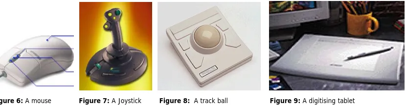
Pointing devices are often used to control the location of the cursor; they control the position of the cursor, which in turn, is used to point at items on the computer. The major pointing devices depend on hand movement to control a cursor on the display. An example of this is the mouse, which was developed around 1964 by Douglas Engelbart [fig.3-5].
Figures 3-5: Images of the first prototype
Table 2: A classification of 2D pointing devices.
The mouse is an indirect input device, which captures planar movements [fig.6]. It provides information on the relative movement of the ball within the housing and can be physically lifted up from the desktop and located in a different position without moving the cursor. This offers the advantage that less physical space is required for the mouse, yet suffers from being less intuitive for novice users. Since the mouse sits on the desk, moving it about is easy and users suffer little arm fatigue [Dix et al. 98].
The joystick [fig.7] on the other hand senses rotation about two axes, which makes it easy for users to move a cursor around on the screen rapidly, but precise or drawing actions are difficult. Some other familiar input devices are the trackball [fig.8] and the digitising tablet, which provides positional information by measuring the position of some device on a special tablet [fig.9].
Figure 6: A mouse Figure 7: A Joystick Figure 8: A track ball Figure 9: A digitising tablet
The effectiveness of pointing devices is illustrated in the following table, proposed by Gribnau [99]:
Factor Description
Pointing time Accuracy Footprint Acquisition time Cost
User preference
The time needed to acquire objects on the screen
The accuracy with which objects can be identified on the screen The amount of desk-space occupied when using the device The time needed to grasp the device
The amount of money paid for the device
The usability of the device as indicated by the user
Positioning in 3D space
The move from 2D input devices to 3D devices usually involves a change from two degrees of freedom to six degrees of freedom. The following devices are examples of 3D input devices:
The 6Dmouse [fig.10] offers intuitive multi-dimensional control. It allows users to control up to 6 input parameters (X, Y, Z, roll, pitch, yaw) simultaneously. The 6D-Mouse maps movements in real 3D space to identical movements in a virtual space [Virtual Reality, URL].
The SpaceMouse [fig.11, 12] allows for interactive motion control of 3D graphic objects in up to 6 simultaneous degrees of freedom. Slight pressure of the fingers onto the cap of the SpaceMouse is enough for generating small deflections in the X, Y and Z directions. Slight twists cause rotational motions of a 3D graphics object around the corresponding axis. The ergonomic design allows a human hand to rest on the device without fatigue [LogiCad3D Product, URL].
The Cubic Mouse [fig.13] is an input device that consists of a box with three perpendicular rods passing through the centre and buttons for additional input. The rods represent the X-, Y-, and Z-axes of a given coordinate system. Pushing and pulling the rods specifies constrained motion along the corresponding axes. Embedded within the device is a six degree of freedom tracking sensor, which allows the rods to be continually aligned with a coordinate system located in a virtual world [Institute for Media, URL].
Data Glove [fig.14, 15] is a device based on a glove worn by the user with flexible sensors, which accurately and repeatably measure the position and movement of the fingers and wrist reporting its location and orientation in space. The user can use the Data Glove to interact with virtual three-dimensional objects in the same way as with real objects through gestures. It provides easier access to highly accurate information, but is a relatively intrusive technology, requiring the user to wear the special Lycra glove. Being able to control the computer with certain movements of the hand would be advantageous in many situations where there is no possibility of typing, or when other senses are fully occupied [Dix et al.98].
Figure 13: A cubic mouse Figures 14, 15: The CyberGlove System
1.5.2 Output devices
Visual output device
Because of the two dimensional display provided by the current computer systems, the visual feedback does not help the user to evaluate the 3D model as he/she can do with the physical model. Some other systems provide the user with stereo view, which display two different images, one for each eye. An example of such a system is the stereo glasses with the Intersense tracker [fig.16]. The Intersense tracker is a gyroscopic tracker, which senses changes of direction in 3 dimensions. It can be plugged into any serial port on the back of a computer.
In some systems, both stereovision and movement parallax are supported to present the images with the correct perspective to the user. An example of this is the CAVE projection based virtual reality system that surrounds the viewer with 4 screens [fig.17, 18]. The screens are arranged in a cube made up of three rear-projection screens for walls and a down-projection screen for the floor; that is, a projector overhead points to a mirror, which reflects the images onto the floor. A viewer wears stereo shutter glasses and a head-tracking device. As the viewer moves inside the CAVE, the correct stereoscopic perspective projections are calculated for each wall. The user carries a physical three button wand to interact with the virtual objects in the CAVE. Since the user can see their own bodies, users have a true sense of being inside the virtual environment.
Haptic output devices
3D touch technology makes working in three dimensions more natural, efficient and intuitive by allowing users to have continuous, two-way interaction with their work.
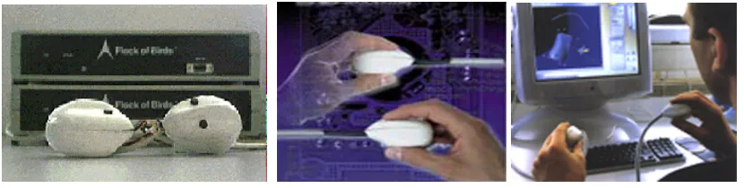
The PHANTOM haptic device is a cross between a 3D stylus and a Space Ball or Space Mouse [fig.19, 20]. It gives the user comprehensive 3D orientation facilities plus the force feedback characteristic of haptic devices that allows the user to touch and manipulate virtual objects. Before the PHANTOM, computer users only had the capability to interact with the machine through the sense of sight, and more recently, sound. The sense of touch, the most important sense in many tasks, has been noticeably absent [SensAble Technologies, URL].
The CyberGrasp haptic feedback interface [fig.21, 22] enables Cyber Glove users to actually ‘touch’ computer-generated objects and experience realistic force feedback via the human hand. The device exerts grasp forces that are roughly perpendicular to the fingertips throughout the range of motion, and forces can be specified individually [Virtual Reality Products, URL].
Figures 19, 20: The PHANTOM haptic interface Figures 21, 22: The CyberGrasp haptic feedback interface
1.5.2 Novel pointing devices
Foot Mouse: Although most mice are hand operated, not all are-there is a device called the Foot Mouse a foot-operated device. The cursor is moved by foot pressure on one side or the other of a pad.
Eye tracking: Several researchers have developed eye tracking; gaze-detecting controllers and companies who make devices to assist the handicapped. The eye gaze system consists of a small matchbox-sized unit mounted on a headband that is worn over the user’s head. Sitting in front of the eye, a low-power laser is shown into the eye and is reflected off the retina. The reflection changes as the angle of the eye alters, and by tracking the reflected beam the eye gaze system can determine the direction in which the eye is looking [Barfield and Furness 95]. Computer vision: Computer vision is a vast subject. Video cameras can be relatively easily interfaced to many computers, and there are many algorithms available to process the resultant images. This provides rudimentary vision for the computer, and open up a whole wealth of interaction possibilities. With decent vision systems, it would be possible for computers to recognize their users and tailor the system their perceived requirements [Dix et al.98].
1.5.3 Using multiple interaction devices
Adding new input devices to computers, as well as adding the capability to support multiple input devices, as Chen and Leahy [90] pointed out, increases the communication bandwidth between the user and the computer. However, most existing computer systems support only the two most common input devices: a mouse and a keyboard that represent a narrow bandwidth channel through which the user has to pass. People who want to use new input devices must buy software that has been specifically written to use them.
C h a p t e r 2 – R e l a t e d W o r k
There are a few similar experimental systems, which have shown the potential of two-handed interaction for both 2D and 3D applications, to compare with the work described in this thesis. In the following paragraphs two examples will be introduced in which some of the concepts, described in chapter 1, were applied:
2.1 IDEATE Research Projects
The first example is the IDEATE Research Projects of the Delft University of Technology, Sub Faculty of Industrial Design Engineering in the Netherlands.
The IDEATE research is comprised of a number of integrated projects which concentrate on the actions of designers during the conceptualising phase of the industrial design process. Starting as an explorative study into the development of a tool for conceptual modelling. It gradually developed into formal studies of two-handed interaction with computer systems. Studies have been done to determine the way designers think and work during the conceptualising phase and interact with a computerized workplace. Multiple techniques were explored to test whether they could lead to 3D modelling systems that are more intuitive and therefore better suited to conceptual modelling.
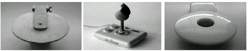
At the beginning of the IDEATE research project, an experimental system was conceived as part of a computer system supporting 3D modelling with two hands. A turntable device [fig.23, 25], used with the non-dominant hand, was built in the first attempt to create a two-handed modelling environment. It was developed together with a device known as the Grabber [fig.24], which is used with the dominant hand. The Grabber is a modified joystick with a shape such that it positions the hand into a natural grasping posture. The first version of the Turntable consists of a disk that is rotated around a central axis. The disk can be only tilted up and down [fig.23]. The turntable was not intended to be used as a pointing device [Gribnau and Hennessey, URL]. It is a specialized device since it cannot be used to identify and position objects. The research of this system was the starting point of the research project with another device known as the Frogs [fig.26], which is not designed for the specific use with either hand but instead primarily designed for 3D interaction with both hands [fig.27]. In the frog design, several issues have been addressed, resulting in a device that can be held between the fingers for a precise manipulation tasks [fig.28]. The main design considerations were that the form of the Frog should afford a precision grip that offers the user control over the feedback about the positions of the controlled objects. The second consideration is that a button should be introduced for clutch mechanism. When the button is pressed output from the input device is ignored, the device can then be orientated without influencing the task it is connected to. This is analogous to lifting the mouse when moving the cursor to the location out of reach [Gribnau et al. 98].
Figure 23: Version one of the Turntable. The turntable device utilised an analogy with the potter’s wheel. Figure 24: The grabber is an ergonomically shaped controller on top of a modified joystick.
2.2 Designing Storytelling Technologies
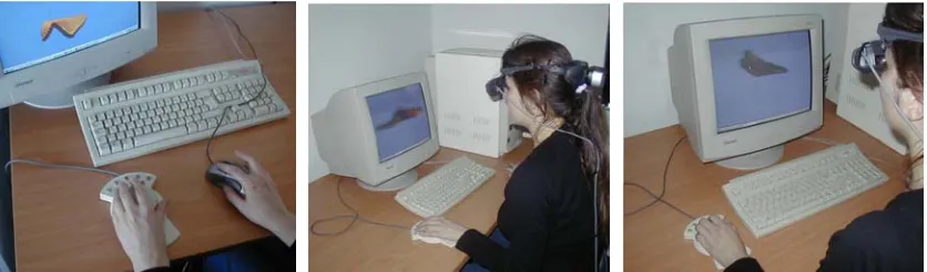
The second example that explores the potential of using multiple input devices is the iterative design of two collaborative storytelling technologies for young children, KidPad and the Klump. The Human-Computer Interaction Lab (HCIL) at the University of Maryland USA in collaboration with the University of Nottingham UK, the Royal Institute of Technology (KTH) in Stockholm Sweden and The Swedish Institute of Computer Science (SICS) Sweden, have proposed a new approach to designing shared interfaces that is intended to develop collaborative storytelling technologies for young children. The project focuses on the idea of designing interfaces to subtly encourage collaboration among children, enabling them to work together when they are in the same place at the same time. Thus children can discover the added benefits of working together [fig.29]. In its first phase, KidStory has worked with two pre-existing technologies, a shared drawing tool called KidPad and a shared 3D environment called the Klump (an application of the DIVE collaborative virtual environment system), both initially with one mouse and later with multiple mice [fig.29, 31]. The KidStory technologies are based on the approach of Single Display Groupware SDG, where several children collaborate using a single computer and display through the use of multiple input devices, for example, two independent mice [Benford, S. et al. 2000].
In summary, this chapter outlined the two approaches, which demonstrated that the use of new and multiple input devices can offer exciting opportunities for human-computer interaction.
This first example had the same technological basis and difficulties as the research carried out in this thesis, but the emphasis was on the study of the interaction devices and the interaction techniques as a means to improve the interaction between the designer and the computer system for modelling during the conceptual phase of the design process and did not include the effect of using different interaction techniques on the resulting forms. Whereas in the second example the emphasis was on the benefits of using multiple input devices to encourage collaboration. The research in this thesis was motivated by the research currently undertaken at the University College London UCL ‘the ARTHUR Project’ in collaboration with GMD-Institute for Applied Information Technology, Ericsson Saab Avionics, Linie 4-Architekten, Aalborg University AAU and Foster and Partners. The ARTHUR has the primary objective to create an innovative use-friendly collaboration environment based on augmented reality (AR) technology. In the following chapter the problem of human-computer interaction will be addressed, and the shortcomings of the interactions with present CAD systems will be described. Subsequently, the objective of the research will be outlined.
Figure 29: Two children using two mice with one computer. Figure 30, 31: Single user and collaborative stretching.
Figure 26: The top view of the frog shows two buttons, used to select objects and to clutch.
C h a p t e r 3 – R e s e a r c h O b j e c t i v e
3.1 Statement of research problem
The problem of human-computer interaction, as Barfield and Furness [95] stated, can be viewed as two powerful information processors [human and computer] trying to communicate with each other via a narrow-bandwidth, highly constrained interface. The user’s side is controlled by the nature of human communication organs and abilities; the computer’s is controlled by input/output devices and interaction techniques that we can create. To address it, we look for faster, more natural, and more appropriate means for users and computers to exchange information. Current technology has been stronger in the computer-to-user direction than the user-to-computer; therefore today’s user-computer dialogues are rather one-sided, with the bandwidth from the computer to the user far greater than that from user to computer.
In the standard desktop set up, the mouse and keyboard are the only interaction devices. This would limit the interaction of the designer with the 3D model. Instead of using a computer with one device, argued Gribnau [99], a situation can be imagined with multiple devices. The presence of multiple devices on a system promotes the use of two devices at the same time, specially adapted for each hand. Or the designer can use several devices, each device designed for a specific task. Then he/she can select the device that is most appropriate for the task at hand. Computer systems are generally operated with one hand only, encouraged by applications that do not support the use of multiple interaction devices. In most CAD systems, the use of the second hand is often restricted to pressing some function keys on the keyboard. This would prevent these systems from being used for modelling at the early stages of the design process, in which designers need ambiguity and lack of restrictions.
In addition to that, 3D modelling applications are in general complex and non-intuitive. One essential problem is that manipulation of 3D objects is very difficult for non-experienced users. Many applications are available in the area of 3D modelling and scene manipulation, but generally these products are difficult to use and require many hours of training. For example products such as Maya [Alias/Wavefront] and 3D Studio Max have several menus, modes and extensive functionality for 3D model creation and manipulation, which is consequently very intimidating for an untrained user.
Most current computer interfaces do not support 3D interaction with two-handed operations that have mostly been tested only in some experimental systems. The consequence is that little is known on how to optimally apply these interaction concepts for form creation. Therefore many questions are expected to arise during the research.
3.2 Research objective
The research investigates the interaction with and the creation of complex forms through direct manipulation. Tools will be created through which the user can control different parts of a surface interactively.
The thesis project attempts to explore how the nature of interaction with the computer determines the suitability of the system for modelling at the early design stages and affects the possibility of generating unexpected and interesting forms.
C h a p t e r 4 – M e t h o d o l o g y
In the previous chapter, it was established that current CAD systems with the standard desktop set-up imposes a limit to the degree of interaction that a user can have with the system.
In this chapter, three models with three different initial configurations are presented, using C++ programming language with two systems: WinNT, with a mechanical mouse in the first two models and Win98 with DirectX 8.0 and two USB mice in the third model. The reasons for this are purely technical and evolved during the development process.
Three models that illustrate the approach used in the thesis were developed. The first model applies a single input device; a mechanical mouse. The second one explores the effectiveness of a two-handed computer- supported modelling environment and finally the third model, which investigates 3D modelling supporting the simultaneous input from multiple devices with two hands and the effect of using MID on generated forms.
4.1 Tools used in the project
The aim of the thesis is to create a surface, which would generate different surfaces with different properties through direct manipulation.
The programming language used is C++ with Cosmo 3D libraries based on OpenGL.
The C++ program was developed in collaboration with Chiron Mottram and Alasdair Turner, VR Centre for the Built Environment, University College London.
4.2 The process
The main idea is to explore the creation of different forms generated by using different interaction techniques [single/multiple input device] to create a large amount of differentiated objects. The model is made up of voxels [3D pixels like sugar cubes]. By using an array of elements, in this case 400, a simple surface is created, based on an array of a geometrical simple form; a cube [fig.32, 33]. The following figures illustrate different surfaces with different cube size:
Figure 32 Figure 33
Figure 34 Figure 35
Through using a set of rules that defines the relation between the selected cube and its neighbours the simple initial surface would be altered in each individual case – with each interaction with the cubes –creating a visual effect of continuously changing surface material properties:
The relation between these voxels could be controlled through a variable: the surface properties variable. The advantage is that by changing its value, either by a button click of the mouse, a key press of the keyboard or by using another mouse depending on the interface used in each model, the properties of the surface would be changed creating an infinite amount of different forms [fig.36, 39].
void morphModel (int x, int y) {
csVec3f ot,t,ct;
csRotation r;
g_tr->getRotation(r); g_tr->getTranslation(ot);
float chngex = float(x)*0.01f ;
float chngey = float(y)*0.01f ;
float chngez = 0.0f;
csVec3f dir(chngex,chngey,chngez); csMatrix4f m;
viewer->getMatrix(m); m.invertFull(m); dir.xformVec(dir,m); t[0]=ot[0]; t[1]=ot[1]; t[2]=ot[2];
for ( int p = 0; p < 400 ; p++) {
{
csTransform *tr1 = array[p]; tr1->getTranslation(ct);
float dist = ct.distance(ot);
float Surface_Properties_Variable = 0.05f;
dist = 1.0/(1.0+dist*Surface_Properties_Variable);
ct[0]=ct[0]+dir[0]*dist; ct[1]=ct[1]+dir[1]*dist; ct[2]=ct[2]+dir[2]*dist; tr1->setTranslation(ct);
Interaction with the user is generated through direct manipulation of the cubes, which allows the user to control the overall form of the surface through mouse drag.
Using a surface, which is built up from cubes has two advantages: first the user can easily click any part of the surface [any cube] to manipulate the whole surface and second different forms could be generated resulting in different geometry with different material properties [fig.36-39].
Figure 36-39: Different actions result in different form- types
The code in this thesis takes advantage of these interactive features in order to create flexible manipulation tools [see CD- Rom].
4.3 The effect of the surface properties variable on the created form
In order to test the effects of changing the surface properties variable on manipulating the surface and the resulted form, I experimented with different values of the variable shown in detail in the following figures [fig.40-45]:
Figure 40 Figure 41 Figure 42
Figure 43 Figure 44 Figure 45
Changing the value of the variable creates a profound change to the surface and its behaviour when being dragged, particularly when using two input devices. The overall image can be altered completely [model 3, chapter 4.6.3].
The decision was made to use the value [0.1] as a starting value [fig.42], which would result a smooth surface that can easily be deformed, but is not too pliable [subjective decision].
Randomness
Introducing a certain amount of randomness in the surface properties variable will create less regular forms with different visual properties. The following figures illustrate different results using total randomness in some examples and a certain amount of controlled randomness in the other ones [fig.46-48].
Figure 46 Figure 47 Figure 48
for ( int p = 0; p < 400 ; p++) {
{
csTransform *tr1 = array[p];
tr1->getTranslation(ct);
float dist = ct.distance(ot);
float Surface_Properties_Variable = 0.1f;
dist = 1.0/(1.0+dist*Surface_Properties_Variable);
ct[0]=ct[0]+dir[0]*dist/10; ct[1]=ct[1]+dir[1]*dist/10; ct[2]=ct[2]+dir[2]*dist/10; tr1->setTranslation(ct);
4.4 Subjects
Due to the limited time available to carry out the experiment, only a small number of subjects could be invited to test several conditions. A within-subject design was chosen that means each user performs under different conditions: although the inevitable transfer of initial learning effects to any later test was not ideal, the limited research time made this method the most efficient. There is also less chance of effects from variation between groups [Dix et al. 98]. To reduce variability in the experiment, it was decided to invite right-handed subjects who had considerable experience with CAD systems only; none of them experienced the SpaceMouse before, tested in the second model. Each subject tested the three models on the same day. Information was collected through observing the users and asking them to elaborate their actions by ‘thinking aloud’: describing what they believe is happening, why they take an action and what they are trying to do.
4.5 Establishing independent variables
Two independent variables were established that could be manipulated to produce different conditions for comparison. The first variable is the interaction devices used in the different models, the second one is the surface properties variable. Each of the variables is given a number of different values [levels] [Dix et al 98], which vary in each model. To reduce variability in the experiments, it was decided that the properties of the input device would be neglected. The dependant variable, which is affected by the independent variable, is the diversity of the generated form and the easiness of creating it, which cannot be measured easily in an objective way.
4.6 Models
The research and application development evolved 3 models that will be illustrated in the following paragraphs:
4.6.1 The first model
Goal
The goal of the first model was twofold. First, it should establish the influence of using a single input device; the mechanical mouse, in deforming the initial surface. It is particularly interesting to find out if subjects could generate interesting forms with a single input device. Second, it should establish whether or not users would be able to control the manipulation and orientation of the surface in all directions with a single input device easily.
Experimental set-up
The experiment was conducted using standard desktop set up with a 19-inch colour display; the standard mechanical mouse is the only input device [fig.49, 50]. The Operating system is WinNT 4.0 and the experimental software: Visual C++ 6.0 with Cosmo 3D Libraries.
Figures 49, 50: The experimental set-up in the first model.
Results
Interaction devices
For the form manipulation task in the first model subjects were offered a single input device; a mechanical mouse.
In the first model the interface is very simple, the only device for interacting with the surface is the mouse. Subjects were given the task of deforming the surface and testing the available possibilities to create interesting forms.
As themouse is the only interaction device, users use it for two main tasks: orienting the object and manipulating it. That means they had to toggle between two modes; either the input device controls the orientation of the surface [fig.52] or the manipulation of it [fig.53] to accomplish the task with the same pointing device.
Figure 51 Figure 52 Figure 53
In addition to that, as stated in chapter 1, the mouse is an indirect input device that operates in a planer fashion. It cannot be used directly to specify orientations in 3D because it measures displacements in two directions while to orient the surface, rotations about three axes must be controlled. For example, to rotate the model around the y-axis the users should move the mouse in a left-right motion [fig.56], whilst rotating the mouse around the x-axis requires moving the mouse away-towards the user [fig.55]. Therefore manipulation cannot be accomplished directly, which forms an obstacle for intuitive and fast manipulation.
Furthermore, the computer screen as output device limits the designer in the evaluation of and the interaction with the 3D scene. The cubes could only be moved in a plane parallel to the screen
.
To drag a certain cube, which is displayed away from the user he/she had to perform a sequence of movements in different directions to get the right view of the object. Therefore, the user had to decompose the intended 3D deformation of a surface onto successive 2D movements with the mouse, which is a cumbersome procedure.Surface properties variable
The system was tested using different predefined initial values for the surface properties variable, which were changed manually by changing the code [paragraph 4.3].
The experimental results showed that the manipulating a surface with a fixed predefined value for the surface properties variable would lead to creating surfaces that react toward the manipulation in a predicted way. The behaviour of the surface could be easily estimated following the direction of the mouse drag [fig.57-59].
Figure 57 Figure 58 Figure 59
An alternative would be to have the option of changing the variable value accessible to the user. The simplest method, from a systems standpoint, is to use the mouse buttons to switch between the values. This scheme, while adequate, is rather unnatural. First, the user has to remember which mouse button accomplishes the appropriate function for increasing the variable value or decreasing it, and second, the workload on the operating hand will increase.
Another option would be to use the keyboard to introduce three additional functions:
(-) Key: to decrease the surface properties variable value: the lowest value is 0.05, choosing a lower value will create a very solid surface that can hardly be manipulated.
(+) Key: to increase the surface properties variable value: the highest value is 1.0, choosing a higher value, will make the user loose control on the resulting form.
(a) Key: to change the surface properties variable randomly.
(*) Key: returns the model to the initial state before starting the deformation.
Introducing these functions would give the user more possibilities to manipulate the surface with different values of the surface properties variable successively, which would lead to more interesting results, and the interface will become more usable in creating a variety of surfaces with different properties. But it will make the user be involved with the system, instead of concentrating on the task at hand.
Figure 60 Figure 61 Figure 62
To conclude: in the first model using the mouse in the standard desktop set-up imposes a limit to the degree of interaction that a user can have with the 3D model. In order to work with the first model the task load on the user would be relatively high.
Figure 63 Figure 64 Figure 65
Figure 66 Figure 67 Figure 68
4.6.2 The second model
The results of the previous experiments motivated the study on the potential two-handed operation, to provide the user with more direct relationship with the manipulated form. In order to overcome the problem mentioned in the first model, concerning reviewing the interaction with a 3D model on a 2D projection of the scene, which affected the users performance, the second experiment was conducted using a 3D visual output device; the stereo glasses. In this model the surface used was built up from 400 cubes, like the first model, but the cubes are overlapping each other, creating a very dense tissue [fig.83-91].
Goal
The goal of second model is to establish the effectiveness of using two-handed operation, in deforming the surface to generate new forms. It is believed that using two-handed operation will reduce the barrier between the designer and the manipulated model. Another aim is to test the influence of using the stereo glasses on the 3D perception of the 3D model.
Experimental set-up
The experiment was conducted using standard desktop set up similar to the set-up used in the first model, except for the input and output devices:
A SpaceMouse [Magellan] for the non-dominant hand was introduced in the second model as outlined below. This was in addition to the mechanical mouse used in the first model [fig.73-75]. As mentioned previously, current CAD systems do not support multiple devices. A big advantage in using the SpaceMouse is that it plugs into a standard serial port without the need for a special system. In addition to that, it is comparably precise and can be slightly translated and rotated so that the user receives a feedback for his/her action. The SpaceMouse is comfortable to use since it is placed on the desk, so that the user's arm can rest on it without getting tired and it is rather inexpensive compared to the CAD software and hardware, as [Stork and Anderson 96] pointed out. The 3D Motion Controller works by providing a spring-mounted puck, which the user manoeuvres in order to provide motion and rotation information to the computer [fig.72].
Magellan is used in conjunction with a 2D mouse [fig.73]. The user can orientate an object with Magellan with the non-dominant hand, while working on the object using a mouse. This will enhance the performance and increase overall productivity in 3D manipulations. The analogy to this would be a workman holding an object in his left hand and working on it with a tool held in his right hand.
To provide the user with 3 dimensional visual feedback, and help the user to evaluate the 3D model as he/she can do with the physical model, stereo glasses were chosen for the output of stereoscopic images [fig.74]. They are comfortable to use due to their lightweight.
Figures 73-75: The experimental set-up for the second model.
Results
Interaction devices
One of the observations in the previous experiment was that users sometimes struggle to deform a surface; they often split a task that would ideally be performed in a single integral movement into two or more sub-tasks. This problem is even more acute when the task requires simultaneous manipulation of all three dimensions; the consequence is that they had to switch constantly between manipulating the object and orienting it. Therefore, a specific device is needed that allows the designer to specify a position and orientation in 3D in uninterrupted movements and is different from the device that enables a grasping function. Thus, the 3D object can be easily and intuitively altered through interactive manipulation using both hands. For this reason the SpaceMouse [Magellan] is introduced in the second model [fig.72].
Observations of users operating the system indicated that there are situations where unconstrained movement is not desirable and where limiting the degree of freedom is preferred, when for example a designer wants to rotate an object about one axis only.
As the SpaceMouse has (9) programmable buttons, constraints could be introduced to control the desired axis of rotation targeted to the task by assigning different functions to different buttons.Users control three-dimensional movements by manoeuvring the SpaceMouse and through pressing and twisting the puck [without choosing any button]. By pressing a button while manoeuvring the SpaceMouse, users can specify the desired axis of rotation.
To give the user different possibilities to rotate and translate the model, four buttons were programmed in the SpaceMouse for the experiment as follows:
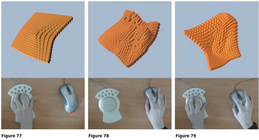
Figures [77-79] show how the SpaceMouse can control the orientation of the surface and the mouse can be used to drag the surface. Moreover the combination of rotation of an object with the SpaceMouse and movement of vertex on the surface with the mouse may lead to unpredictable and interesting results. One advantage of using the SpaceMouse is that the concurrent dragging and orientation of the cubes provides far greater potential for form variability. For example when the user clicks on a cube and drags the whole model or translates it from one place to another. This will lead to diverse results in a short time, depending on the direction of dragging, because all the cubes in the neighbourhood of the moved one will be displayed towards or away from the user due to the SpaceMouse rotation, which may lead to interesting results shown in the following figures:
Figure 77 Figure 78 Figure 79 Button 1: allows controlling the rotation around the X-axis.
Button 2: allows controlling the rotation around the Y-axis. Button 3: allows controlling the rotation around the Z-axis. Button * : returns the model to the initial state before starting the deformation.
Observations of users operating the SpaceMouse indicated,as stated previously and similar to the results presented by Gribnau in his research with the Turntable [Gribnau and Hennessey, URL], that working with two hands in 3D can indeed be fast and effective. A two-handed system could have performance benefits for two reasons. First, two-handed operation can avoid the toggling between orientation and manipulation mode and second, the temporal overlap of the actions performed by each hand could improve performance leading to new forms.
Furthermore, using the stereo glasses enhances the predictability of the outcome of the user’s actions, but still the mouse, as a 2D interaction device, forms an obstacle for intuitive and fast manipulation of 3D objects, as experienced in the first model [fig.54-56].
An attempt was made to enhance the predictability of the location by attaching a white sphere to the mouse cursor [fig. 80-82]. In this case cursor movement over the surface is more obvious. But because of the existence of the mouse cursor, confusion would occur due to the conflict in reading the information on the 2D display.
Figure 80 Figure 81 Figure 82
Surface properties variable
Figure 83 Figure 84 Figure 85
Figure 86 Figure 87 Figure 88
4.6.3 The third model
The results in the second set of experiments motivated the study of multiple input devices MID, providing the user with new possibilities for manipulating the form.
In the following part the third model is illustrated in which aspects of two-handed interaction are tested for concurrent two-handed activity and the influence of using MID on the form creation and manipulation.
Goal
The goal of the third model is to explore the influence of using multiple input devices; it was particularly interesting to find out if using MID would offer a more efficient and richer type of interaction to generate diverse forms.
Experimental set-up
The third experiment was performed using a standard desktop set up: with two interaction devices; two USB mice with a USB hub [fig.92-94]. The Operating system is Win 98, with the software: Visual C++ 6.0 with Direct X 8.0 and Cosmo 3D Libraries. Since none of the available CAD systems supported two-handed operations, a system had to be developed to experiment with two-handed operations as outlined below:
The Human-Computer Interaction Lab (HCIL) at the University of Maryland has introduced MID, a Java package that addresses the problem of getting input from multiple devices and offers an architecture to access advanced events through Java [Hourcade and Bederson 99]. However MID could not be used from C++. Therefore a C++ library, which is a free software written by Juan-Pablo Hourcade and Ben Bederson, Copyright (C) 2001 University of Maryland, using DirectX 8.0 to get input from multiple mice, was used in the research. The library was modified by Chiron Mottram, VR Centre for the Built Environment, to get input from two mice, and was incorporated into the C++ program for the third model [see CD-Rom].
The most limiting aspect of the library used is that it currently gets input from multiple mice only under Windows 98, when the mice are USB mice. The mice have to be USB mice because of the limitation of Windows. Windows merges the input from the non-USB mouse with the input from USB mice into one channel. And the operating system should be Windows 98 because WinNT 4.0 doesn't support USB, and in Win2000 mouse streams are merged at a level below DirectX. Another limitation is that, it takes over the system cursor and users can’t send mouse input to other applications unless they switch to other applications through the keyboard [Hourcade and Bederson 99]. For example, to exit the window in the third model the ‘q’ key should be pressed. This was done on purpose because the alternative is to have both mice control the single system cursor.
Figures 92-94: The experimental set-up used for the third experiment.
Because of the reasons mentioned above a new operating system: Windows 98 and Direct X 8.0, with USB mice were used in the third experiment.
Figure 95 Figure 96 Figure 97
Input device and user control
One critical parameter affecting mouse operation is the control-display (c/d) ratio between mouse movement and cursor movement. The simplest form of c/d ratio considers only the distance the user moves the mouse to determine appropriate distance for cursor travel. Given a c/d ratio of 1:1, a one-unit movement of the cursor will result in a one-unit travel of the cursor on the screen. A more complex type of the calculation also considers the velocity of the mouse movement [Blake 90].
Different user operations require different c/d ratios to make them easy to perform. For the experiment it was decided to use the 2:1 ratio, and because it is based on 2D user interface, the C/D ratio is one uniform scaling factor for both horizontal and vertical dimension.
Results
Interaction devices
Two interaction devices, two USB mice, were used to explore the use of two-handed operation. It is believed that more possibilities would be offered by using additional interaction devices that were used in the second model. The SpaceMouse and the stereo glasses could be tested with the two mice to see their influence as well. [For all possibilities see the table in the CD-Rom]. However, to narrow the scope of the research enough to make it feasible within the timeframe of an MSc project, it was decided to focus on using two mice for two-handed interaction primarily.
For the deformation task in the third model subjects were offered one mouse for each hand, with three different initial configurations assigned to the mice are presented in the following part:
In the first configuration the interface provides the same functionality for both hands, both mice were used to control the surface in the same way with the same surface properties variable [fig.111-113], each mouse could be used for orienting and manipulating the surface, like in the first model, as described in paragraph 4.6.1.
Figures 98, 99: Using traditional unimanual techniques, moving cube A and cube B in opposite directions requires (multiple) iterations of orientation, rotation, and dragging for both cubes successively. In contrast, using a bimanual technique that assigns two hands to controlling two opposing cubes, all of the three aspects can be chunked into one integrated process, which is closer to how one naturally views such a task.
However, some users did not use both hands all the time in the same degree, instead they focused on using the dominant hand. The non-dominant hand was used most of the time to support the dominant hand.
In the second configuration one of the mice controlled the manipulation of the surface and the other mouse controlled only the orientation of it [fig. 100-102], assigning separate tasks to each hand similar to the second model, as explained in chapter 4.6.2.
After trying to manipulate the surface with the dominant hand and orient it with the non-dominant hand, the users commented that operating the mouse with the non-non-dominant hand for the orientation of the surface was not as easy as compared to the SpaceMouse in the second model, outlined in chapter 4.6.2.
Figure 100 Figure 101 Figure 102
In the third configuration both mice controlled the manipulation and orientation of the surface but for the surface manipulation it was decided to choose two distinct effects of the surface properties variable that varied extremely, creating different effects depending on the mouse in use [fig.103-105].
Figure 103 Figure 104 Figure 105
Observation of users manipulating the form indicated that most users adopted the strategy of using both hands simultaneously without being instructed to do so. This result is not surprising, because people use both hands at the same time for many non-computer tasks.
The keyboard had to be used due to the limitations of the MID library, as mentioned in the experimental set-up previously. However, the use of the keyboard was restricted to switching to other applications, or exiting the modelling window with the ‘q’ key.
Surface properties variable
In a similar manner like the configuration for the interaction devices, different surface properties variable were used with the different configurations as outlined below:
In the first configuration, both mice had the same variable with the same effect and value [fig.112-114]. In the second configuration the effect of the surface properties variable was restricted to the mouse in the dominant hand, as the non-dominant hand controlled only the orientation of the surface [fig. 100-102].
In the third configuration, the surface properties variable in the first mouse controlled the surface in a very different way than the surface properties variable in the second mouse. Either by using a different value of the surface properties variable for the second mouse, which makes the surface, react in a different way [fig.103-105]:
for ( int p = 0; p < 400 ; p++) {
{
csTransform *tr1 = array[p];
tr1->getTranslation(ct);
float dist = ct.distance(ot);
float Surface_Properties_Variable = 0.05f;
dist = 1.0/(1.0+dist*Surface_Properties_Variable);
ct[0]=ct[0]+dir[0]*dist/10; ct[1]=ct[1]+dir[1]*dist/10; ct[2]=ct[2]+dir[2]*dist/10; tr1->setTranslation(ct);
Or by using a different effect for the variable:
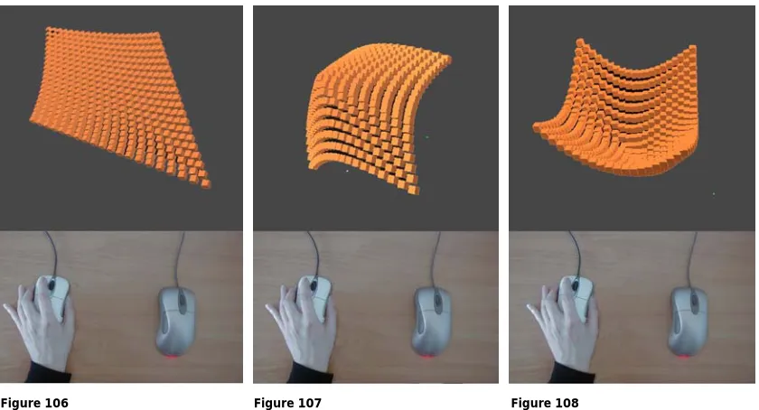
Thus, the first mouse could be used to change details on the form [fig.104] while the second mouse could be used for quick change of the whole form. This tool is very effective, which leads to strong visual effects in a short time, which could be used with the non-dominant hand easily [fig.106-108].
Figure 106 Figure 107 Figure 108
The combination of the two mice provides the user with a tool that results in a rich type of interaction [fig.109-111]. In this configuration the keyboard could be used to change the value of the variable for the first mouse, adding more possibilities for the interaction, analogous to adding water to a clay model [fig.118-120].
Figure 109 Figure 110 Figure 111
for ( int p = 0; p < 400 ; p++) {
{
csTransform *tr1 = array[p];
tr1->getTranslation(ct);
float dist = ct.distance(ot);
ct[0]=ct[0]+dir[0]*dist/10; ct[1]=ct[1]+dir[1]*dist/10; ct[2]=ct[2]+dir[2]*dist/10; tr1->setTranslation(ct);
Figure 112 Figure 113 Figure 114
Figure 115 Figure 116 Figure 117
C h a p t e r 5 – D i s c u s s i o n
First the interactive approach will be discussed, then the interactive tools for form manipulation and creation, presented in chapter 4, will be evaluated and related to some general concepts outlined in the introduction.
In the design process, advanced computer tools typically enter only at a later stage when many detailed decisions about the design have already been made. At the early design stage, which is strategic in that decisions are made that affect the whole process of the design, sketching with pen and physical modelling are intuitively easier to work with and therefore still the most frequently used tools.
A major advantage of using traditional tools for conceptual modelling is the interaction, achieved by the dynamic manipulation of form, between the designer and the object form [Gribnau 99]. Current CAD systems are burdened with the inconsistency between the three-dimensional scene and the two-dimensional input and output devices [2D mouse and display]. Most of CAD systems have extensive functionality and are consequently rather cumbersome to use, especially at the early design stage in which the designer needs freedom, speed and an amount of vagueness, which are not offered adequately by current tools.
One way to improve such systems is by extending the scope for manipulating the object and the directness with which the manipulation can be done. A possible approach would be to develop two-handed interaction techniques that creatively exploit the user’s potential to continuously coordinate both hand movements at the same time every day for many non-computer tasks [Leganchuk et al. 98].
However, two-handed interaction is not new in user interface technology. One of the first computer-graphics programs which provided the user with the ability to use both hands to create, manipulated, duplicated highly precise drawings is SKETCHPAD; a program that Sutherland developed while working on his PhD [1963] at MIT. Users drew directly on the computer screen with a light pen using one hand, and could modify the pen’s action by pressing a button with the other hand [Barfield and Furness 95].
One of the earliest examples of coordinated and integrated bimanual interaction, where both hands were performing continuous, rather than discrete tasks, was established by Krueger in 1983. He demonstrated that users should be able to manipulate graphical objects like objects in the physical world, using both hands to stretch, position and rotate boxes and other graphical objects in an intuitive and natural manner [Leganchuk et al. 98].
What is less clear is why barely any user interfaces allow us to employ this demonstrated ability for computer support conceptual modelling. This has motivated the investigation the potential of 3D interaction and two-handed operation for computer support conceptual modelling.
The research in this thesis focuses on the nature of interaction with the computer, which will determine the suitability of the system for modelling at the early design stages. It explores the potential benefits of two-handed interaction for modelling and its effect on generating unexpected and diverse forms.
The experiments were conducted within a C++ environment using standard desktop set up. Different user-interfaces were developed in order to enable the user to manipulate a 3D surface with different interactive tools and test the effect of these tools on the resulting forms.
The characteristics of the experimental surface, as explained in chapter 4 paragraph 4.3, are determined through the surface properties variable. Changing the value of the variable has a significant influence on the surface and its behaviour when manipulated. This would result in a very wide range of surfaces with different properties, providing the user with a tool to create surfaces with a diverse degree of complexity. However, some negative aspects related to the value of the surface properties variable were pointed out, such as creating a very rigid or an extremely pliable form that could not be easily controlled.
In the experiments, three models employing surface deformation for form creation were used:
The first and the second models with bimanual interaction techniques.
![Table 1 presents the classification proposed by Barfield and Furness [95]:](https://thumb-us.123doks.com/thumbv2/123dok_us/7954676.1319936/9.595.114.525.680.782/table-presents-classification-proposed-barfield-furness.webp)