Agent Behaviour Simulator (ABS):
A Platform for Urban Behaviour Development
Franco Tecchia, C´eline Loscos, Ruth Conroy, Yiorgos Chrysanthou
University College London
Department of Computer Science
Gower Street
London WC1E 6BT
UK
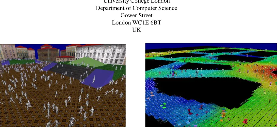
Figure 1: The behaviour of the agents for a game (such as that on the left) can be easily developed using the tools provided by ABS (on the right).
Keywords
Behaviour simulation, agents, pedestrian movement, real–time vi-sualisation, virtual cities simulation.
Abstract
Computer Graphics have become important for many applications and the quality of the produced images have greatly improved. One of the interesting remaining problems is the representation of dense dynamic environments such as populated cities. Although recently we saw some successful work on the rendering such environments, the real–time simulation of virtual cities populated by thousands of intelligent animated agents is still very challenging.
In this paper we describe a platform that aims to accelerate the de-velopment of agent behaviours. The platform makes it easy to enter local rules and callbacks which govern the individual behaviours. It automatically performs the routine tasks such as collision detec-tion allowing the user to concentrate on defining the more involved tasks. The platform is based on a 2D-grid with a four-layered struc-ture. The two first layers are used to compute the collision detection against the environment and other agents and the last two are used for more complex behaviours.
A set of visualisation tools is incorporated that allows the testing of the real–time simulation. The choices made for the visualisation allow the user to better understand the way agents move inside the world and how they take decisions, so that the user can evaluate if it simulates the expected behaviour.
Experimentation with the system has shown that behaviours in environments with thousands of agents can be developed and visu-alised in effortlessly.
1
Introduction
Computer graphics have become an important domain and are widely used for games and entertainment as well as for medi-cal, architectural and cultural applications. At the current stage of technology, a user can interactively navigate through complex, polygon–based scenes with a high rendering quality that includes anti–aliasing and sophisticated lighting effects. It is also possible to animate characters (or agents) and to interact with them. Cur-rently most agents’ behaviour is relatively simple with more com-plex behaviours being pre–computed and the resultant animation se-quences being replayed triggered by the modes of interaction. To generate such animations, the behaviour has to be defined for each agent, which is time–consuming. However, if the user is to interact with thousands of other individual agents this approach is clearly unusable. Defining the behaviour for each agent is laborious whilst updating each of the thousand agents is computationally expensive for interactive applications such as games.
The initial motivation of this work was to develop and inter-act with realistic populated urban virtual environments, with all the crowds and traffic that come with it. In previous work [13], a real– time city renderer was developed that allows the visualisation of thousands of animated human walking randomly. An example of this system is shown in Figure 1. Although this system has already produced a lively, animating effect for a complex polygonal city, the random behaviour of the humans is far from giving the impression of intelligent agents. It is clear that we need to provide more realistic and complex behaviours such as awareness of pavements and other pedestrianised areas, interacting with cars (and other vehicles), stop-ping at points of interest and walking in small groups of people.
to understand how complex behaviours emerge from simpler rules with the emergent behaviour often being quite unexpected. Instead of working directly with the rendering system, which could hinder the evaluation of the tests and mask some of the behaviour, we have developed a platform to make the process of behaviour creation and evaluation far easier. The platform provides a framework to effort-lessly input simple rules, while taking care of the collision detec-tion against the model and between agents. It also provides a 3D-visualisation with functions for tracking individual agents and visu-alising their path over time. The platform is scalable and allows a researcher or a game–developer to focus on real–time simulations as the behaviours may be tested on as many agents as are ultimately required in the city. In other words, there is no need to test be-haviours on a smaller sub–sample of the final, projected population. The tested behaviour can then be integrated in the system to be ren-dered and animated in a more human–like manner.
When the agents’ behaviours are created, the evaluation of their efficacy (in term of realism) is often quite difficult to perform accu-rately. Techniques such as Space Syntax analysis [4, 5] can be used to analyse the spatial configuration of the city, predicting probable pedestrian–flows in a real city. These same techniques could be used to provide a ’yard–stick’ against which the emergent behaviour may be measured and correlated. In this paper, we do not provide tools for such evaluation, but we believe that the system we have devel-oped could be extended to perform such evaluations.
1.1
A platform to aid behaviour development
In this paper, we propose a platform to develop and visualise in real– time the behaviour for thousands of agents. It is based on a segmen-tation of the space into a two–dimensional grid. This grid is used to delimit areas in which simple local rules are applied. Each agent is localised in the 2D–grid and hence applies the rules relevant to its position. In the rest of the paper, we will call local behaviour the behaviour resulting from these rules applied to each agent. Using simple, local rules allows the system to be fast enough for real–time simulation.
The local rules are governed by four different layers of the grid, each reflecting a different aspect of an agent’s behaviour. This multi–layer representation allows for an aggregation of different components of the expected behaviour, such as inter–collision de-tection between agents and collision dede-tection with the model, sim-ple general behaviour (but local to an area) and finally more com-plex and individual behaviours.
In the next section, we describe previous work on human be-haviour simulation and discuss the different models used to visualise the behaviour. In section 3, the platform itself is described along with the choices that were made to enable both good functionality and appropriate visualisation. In section 4, some simple examples of behaviours have been implemented using the platform and tested to evaluate the quality of the platform.
2
Background
2.1
Previous work on behaviour
Researchers from different disciplines ranging from psychology to architecture and geography have been making observations of the micro–scale behaviours of pedestrians for over thirty years. For ex-ample, Goffman [3] discusses the techniques that pedestrians use to avoid bumping into each other. Early work of researchers at Uni-versity College London began to systematically develop techniques for observing and analysing patterns of pedestrian flows and corre-lating these to spatial properties of the environments through which people moved. Examples of these techniques are documented in [5] and [4]. Up until this point, observations had been made purely by
hand, with the sole research aim of being able to better understand how people moved through space at a more macro–level (e.g. [4, 5]) and a more micro–scale (e.g. [3]). A second aim was to be able to predict real–world movement. Ideas of using such observations as the basis of rule sets to simulate pedestrian movement or to populate virtual worlds with realistic humans were hampered by computer processing power.
More recently researchers have begun to attempt to devise rule– sets to drive navigating agents. Many techniques have been bor-rowed from, or adapted from parallel work done on real–world navi-gating robots, such as Prescott et al. [11]. Equally researchers work-ing on navigatwork-ing robot problems have occasionally used software simulations to test their ideas. In this way it can be held that there are clear parallels and areas of crossover between the two fields. However, the majority of work, undertaken on simulating pedestrian movement has involved simulating densely populated crowd scenes such as in [9, 7, 8]. Although serving as useful precedents, this work is less useful for games programming, where the aim is frequently to populate environments with realistic individual virtual humans, not crowds.
Work done on non–crowd or natural movement includes early work by Penn et al. [10] in which rules were applied to agents, with distinct groups of agents using different heuristics for navigating from origins to destinations assigned randomly. The resulting paths taken were compared to spatial analyses of the environment and ob-served movement in the corresponding real environment (a district of London). A similar approach of assigning origins and destina-tions served as the basis of a later paper, Farenc et al. [2] in which groups of agents navigated through a cityscape from ’home’ to ’su-permarket’.
Sophisticated variations on natural movement modelling include work done on the weighting and use of interest–attractors by Smith et al. [12]. Attractors in this environment include shop–doorways, recreational areas, and street entertainers. Other refinements of standard natural movement models include Mottram et al. [6] and Thomas et al. [14].
2.2
Previous approaches taken to develop
be-haviour
In Penn et al. [10] the agent behaviour was simulated using the mathematical modelling application Mathematica. The agents were given simple rules such as “follow the longest line of sight”. The re-sultant data was purely numerical which was then transformed into 2D representations of the routes taken by the agents (not in real– time). These rules were later refined and extended to more sophis-ticated agents in Mottram et al. [6]. These later agents were given a restricted field of view and hence, could look around, identifying long lines of sight to follow. Since the environment being simu-lated was an art gallery, the behaviour being modelled was purely exploratory behaviour. This system was run on an SGI UNIX ma-chine using the Performer 3D library. The agents were given rules programmed in a simple scripting language, which was interpreted not compiled, so that the agents’ behaviours could be ’tweaked’ or modified in real–time whilst the system was running, without need-ing to recompile. However, the agents were represented as nothneed-ing more than simple ’cubes’ and the system was limited by allowing only a relatively small number of agents in each world. In both cases the methods used to evaluate the efficacy of the rules, was to com-pare the results to real–world observations and to spatial analysis of the environments.
as well as accommodating sloping, uneven terrain. The direction of the humans was decided randomly resulting in non–realistic be-haviour. Based on a spatial subdivision, the decision process was developed directly in the same system used to render the crowd and the model of the city. As a consequence it was hard to determine if the initialisation of agents’ positions was performed correctly since some agents could have been hidden inside the buildings. To avoid this kind of problems that are difficult to detect and to precisely vi-sualise the simulated behaviour, using a behaviour–dedicated devel-opment platform was necessary.
3
The platform
As mentioned before, it was necessary to develop a new platform to make the process of creating and visualising behaviour easier. With this intention, a platform that allows a user to develop and visualise the behaviour of large numbers of agents was developed. Consid-ering the previous approaches described in section 2, we decided to adopt a 2D–grid upon which the agents navigate. In order to simu-late their behaviour, the platform is composed of four different lay-ers. By combining the effect of each layer, an individual agent reacts depending on the area it is occupying and the relative position of the other agents.
The layers are ordered from the more basic (detection of possible collisions) to the more complex behaviours. Each cell of the grid corresponds to an entry to each layer. When an agent reaches a cell, it checks from the first to the fourth layer to decide what is going to be its next action. One or more cells are checked by each agents for each layer, and the decision on the position and the number of the checked cells is freely made by the user. With the current implemen-tation of the platform, the subdivision of the layers corresponds to the one chosen for the collision–detection grid, but the subdivisions of all grids need not be identical.
3.1
A multi–layer platform
The four different behaviour layers of the platform can be imagined as maps. As explained previously, they are aligned with the 2D–grid representation. In the following, we name and describe these four layers in the same order an agent access them during a simulation.
1. Inter–collision detection layer: This layer corresponds to agent–to–agent collision detection. Before moving to a new cell, an agent checks to determine if the target cell is free. The user can specify how far ahead to check so that the avoidance can be made more smoothly.
2. Collision detection layer: It corresponds to environment col-lision detection and defines the accessibility of areas. An im-age is used as an input to the platform, encoding by white the accessible cells and by black the inaccessible areas. This in-put image could be more complex and used as a height map (relief map or Digital Elevation Model) with grey levels indi-cating the height of the obstacles. By examining its local–area map, an agent can decide if it can pass by, climb up or descend in order to continue its journey, or if it must change direction to avoid an obstacle. An example of such a map is shown in Figure 2(a). In this figure only binary information indicating accessibility is provided, suggesting that the original model is flat.
3. Behaviour layer: This third layer corresponds to more com-plex behaviours encoded for each local region of the grid. A colour map is used as an input file, so that with 8 bits per com-ponent in a RGBA space, up to2
32
distinct behaviours can
be encoded. The user then associates with colour the corre-sponding behaviour. When an agent reaches a cell, it checks the encoded colour to decide which behaviour to adopt. It may be a simple behaviour like ’waiting’ or ’turning left’ or more complex like ’compute a new direction depending on the sur-rounding environment’. For example, we can use a visibility map (see Figure 2(b)) to encode more probable paths, or an attractor map (see Figure 2(c)) which may reflect how agents are attracted by some points of interest such as a bus stop or a shop–window. If requiered, this layer can have several in-put images although it may increase the memory required by the system. Depending on the available resources, one might prefer to compress data into a single image.
4. Callback layer: This is the most complex of all the layers. Callbacks can be associated to some cells of the grid in or-der to simulate more complex agent–environment behaviour. Such callbacks can allow for pushing buttons to call elevators or climbing aboard a bus on its arrival. For the moment, the user needs to specify callbacks for each cell. As future work, we would like to develop a graphical user interface, where any callbacks can be defined as modules that can be integrated by the user by selecting them from a menu. This module can then be associated with a cell or a region of cells selected interac-tively.
The combination of these four layers permits the creation of com-plex behaviours that can appear extremely realistic but can be still executed at interactive rates. With such a platform, we can for ex-ample simulate an agent walking along a pavement to reach a bus stop. Whilst walking along the pavement the agent will avoid obsta-cles such as rubbish bins, telephone kiosks and other agents in front of it. When it reaches the cell that corresponds to the bus stop (for which the associated behaviour is to wait) it pauses appropriately. When the bus arrives, a callback is activated to cause the agent to climb into the bus. Using this simple scenario, we utilise all of the four layers described above. Since each rule is applied only locally, the callback, which is a more complex algorithm, is executed only when needed so that the whole series of behaviours can still be com-puted in real–time even if the environment contains many thousands of agents.
3.2
Visualisation
The purpose of the system is to provide a platform to easily de-velop different types of behavioural rules and to immediately visu-alise them. The following visualisations are important to better un-derstand this methodology.
In other systems the agents are animated and can move about freely, but it is difficult for the developer to ensure that they react in the manner expected. To facilitate the developer’s evaluation, the agents’ motion is rendered in 3D. This 3D representation allows the user to navigate and to zoom into the scene when a precise evalua-tion is needed or to zoom out when a global view is required. The 2D–grid is displayed using a colour for each cell of the grid that is computed by multiplying the input colour values from maps of the collision detection layer and the behaviour layer. The user can op-tionally choose which map to display.
In the simulation process, the number of displayed agents can vary from the number of total agents used for the behaviour sim-ulation. It allows the user to focus easier on agents. Again this is an option of the system and all the agents can also be displayed. Five entities can be displayed for each agent:
(a) (b) (c)
Figure 2: (a) An example of a collision map. The regions where agents can move are encoded in white and inaccessible regions in black. (b) and (c) Examples of behaviour maps. (b) Visibility map. (c) Attraction map.
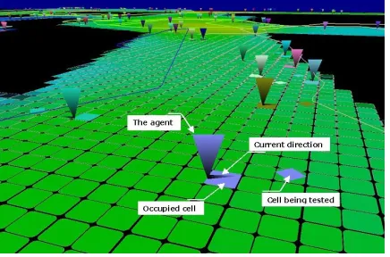
Figure 3: The 3D visualisation of the simulated behaviour.
Figure 4: Explanation of the different visual cues.
The choice of using random colours was to clarify the visu-alisation and not confuse an agent with its neighbour. How-ever, the user could specify a colour for a ’type’ of agent (i.e. tourist/resident or male/female), and the renderer could then render these agents with a colour gradation to enable the de-veloper to visually differentiate them from their neighbours.
A small horizontal triangle is associated to each agent to rep-resent its current direction.
A square is displayed on the grid using the same colour as the agent’s body–triangle and is included to improve the percep-tion of the posipercep-tion of the agent.
Another square of the same colour is displayed to represent the checked cell further away.
Finally, the path followed by agents can be displayed. To clar-ify the visualisation, the user specclar-ify how many paths are go-ing to be displayed. It avoids to display and keep track for thousands of agents, which could confuse the evaluation.
An illustration of the system is shown in Figures 3 and 4. As shown in Figure 4, the vertical triangles represent the agents and the flat small triangles their direction. In this example, the checked cell, represented by a square of the same colour as the agent, is located two cells from the occupied cell. Some trails had been displayed for twenty of the agents (chosen arbitrarily). Figure 3 provides a more global view of the simulated behaviour.
4
Results
The system developed proved to be able to simulate and visualise at interactive frame rates virtual scenarios for large numbers of agents1. To test the platform, we simulated three different simple behaviours. We first tested the collision detection by adding only a collision map to the system without providing any input for the be-haviour layer and the callback layer (see section 4.1). We then tested more complex behaviours by testing changes in direction at junc-tions (see section 4.2). And in the final example, agents remember last change in direction and take that in account (see section 4.3). For these examples the behaviour for a variable number of agents was simulated. We used a 512x512 grid, with each cell in the grid corresonding to a physical area of 30x30
cm
2, and each agent nav-igates over the grid and accesses any available information corre-sponding to its current position. An agent can stand on any point in
(a) (b) (c)
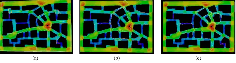
Figure 5: Examples of behaviour simulation. (a) Random walk with collision detection. (b) Same behaviour as (a) with decision taken at junctions. (c) Same behaviour as (b) with agents storing in memory the last decision taken.
a cell (not necessarily the centre) but only one agent can occupy a cell at a time.
We observed that the frame rate was related to the number of agents included in the simulation but not to the behaviour algo-rithm used. This indicates that the graphical rendering of the agents, even in its simplicity is still the major bottleneck in the simula-tion/visualisation. Our simulation runs at 75 Fps with 1000 agents (limited by the video refresh), 37 Fps with 5000 and 21 Fps with 10.000. In the following examples we reduced for clarity the num-ber of agents to 8 and then tracked their movements to show the dif-ferences produced by different behaviour algorithms.
4.1
Random walk
We first tested a random walk combined with obstacle collision– detection and avoidance of other agents. For this simulation, only the two first layers concerning collision detection of the platform are used. The input for the collision map is shown in Figure 2(a). The initial position and direction of the agents were set randomly but were placed inside the navigable areas. Each time an agent encoun-ters an obstacle or an occupied cell, it changes gradually its direction until it finds a free cell. This algorithm was also used in [13]. The collision avoidance behaviour is shown in Figure 5(a). For a small number of agents, the movement is characterised by long straight lines showing that the agent keeps the same direction and do not take any decision. Of course as the number grows larger then the inter-agent collisions grow and so do the number direction changes.
4.2
Choice of direction
In this example, agents navigate through the accessible areas whilst following some rules at junctions. Collision detection is performed using the same collision map as for the previous example. In this case agents use the information provided by the behaviour map to detect junctions [1]. When arriving at a junction, agents are likely to change their heading direction by approximatively 50 degrees. They choose to turn left or right on the basis of a test for obstacles in the 2 candidate directions, trying to discard, if it is the case, the one that is more likely to cause a collision after just a few steps. The agents don’t have any kind of memory, and each decisions is taken independently from the previous one. As it can be seen in Fig-ure 5(b) showing the simulated behaviour, agents tend to change di-rection in correspondence of the junction, generating a more realis-tic behaviour than in the previous case (described in section 4.1. On the other hand decisions are sometimes too frequent, and as it can be seen this can generate unwanted loops in the path of the agents. In this example, only the three first layers were used (inter–collision detection layer, collision detection layer and behaviour layer).
4.3
Choice of direction with memory storage
In the last example, we added to the strategy used in the previous example (described in section 4.2) the concept of “memory”. This is implemented by using a variable local to each agents and indicat-ing to the agents if they are allowed to take a decision. After takindicat-ing a decision, each agent sets a private variable to a arbitrarily fixed value. For each following pass in the algorithm, this value is de-creased until reaching 0. An agent can take another decision only when its memory value is 0. In this way we avoid agents changing direction too often and, as can be seen in Figure 5(c), this results in more regular and “smooth” paths.
5
Conclusion
We have presented a system that facilitates the development and the visualisation of behaviours for moving independent agents. The representation combines a 2D–grid implemented in four–layers to encode different levels of behaviour. We believe that these four– layers can be used to encode complex behaviours. We demonstrate by some results that the system is practical to visualise the simulated behaviour and to evaluate whether it effectively corresponds to the expected behaviours.
For future work, we would like to extend the number of behaviours tested and to integrate the tested behaviour into a crowd simulator currently developed [13], as for example re-duced/accelerated speed along sloped, uneven terrain (slower up-hill, faster downhill). We would also like to enable multi–level sub-divisions depending on the precision needed for each level. We would like to be able to provide a more user–friendly interface that allows the user to associate callbacks (pre–defined or newly written by the user) to cells selected interactively, without needing to go into the code.
6
Acknowledgements
This work was in part supported by the EPSRC project GR/R01576/01 and the EPSRC Interdisciplinary Research Centre equator.
References
[1] R. Conroy and N. Dalton. Omnivista: An application for isovist field and path analysis. In Space Syntax - III International Symposium, Atlanta, Georgia, 2001. to appear.
[3] E. Goffman. The Individual as a Unit. Relations in Public: Microstudies of the
Public Order. Allen Lane The Penguin Press, London, 1972.
[4] B. Hillier, M.D. Major, J. De Syllas, K. Karimi, B. Campos, and T. Stonor. Tate gallery, millbank: a study of the existing layout and new masterplan proposal. Technical report, London, Bartlett School of Graduate Studies, University Col-lege London, 1996.
[5] B. Hillier, A. Penn, J. Hanson, T. Grajewski, and J. Xu. Natural movement: or, configuration and attraction in urban pedestrian movement. In Environment and
Planning B: Planning and Design 19, 1992.
[6] C. Mottram, R. Conroy, A. Turner, and A. Penn. Virtual beings: Emergence of population level movement and stopping behaviour from individual rulesets. In
Space Syntax - II International Symposium, Brasilia, Brazil, 1999.
[7] S. R. Musse, C. Babski, T. Capin, and D. Thalmannet. Crowd modelling in col-laborative virtual environments. In ACM VRST ’98, pages 115–123, Taiwan, November 1998.
[8] S. R. Musse, F. Garat, and D. Thalmann. Guiding and interacting with virtual crowds. In Computer Animation and Simulation ’99, SpringerComputerScience, pages 23–33, 1999. Proceedings of the Eurographics Workshop in Milano, Italy, September 7–8, 1999.
[9] S. R. Musse and D. Thalmann. A model of human crowd behavior: Group inter-relationship and collision detection analysis. In Workshop of Computer Animation
and Simulation of Eurographics ’97, pages 39–52, Budapest, Hungary, 1997.
[10] A. Penn and N. Dalton. The architecture of society: Stochastic simulation of ur-ban movement. Simulating Societies, pages 85–126, 1994.
[11] T. J. Prescott and J. E. W. Mayhew. Adaptive local navigation. In Blake, A. and
Yuille, A. Active Vision, Cambridge, MA, 1992. MIT Press.
[12] D. Smith, S. Pettifer, and A. West. Crowd control: Lightweight actors for popu-lating virtual cityscapes. In Eurographics UK 2000, pages 65–71, Swansea, UK, 2000.
[13] F. Tecchia and Y. Chrysanthou. Real time rendering of densely populated ur-ban environments. In P´eroche and Rushmeier, editors, Rendering Techniques ’00
(10th Eurographics Workshop on Rendering), pages 45–56, Brno, Czech
Repub-lic, June 2000. Springer-Verlag.